In this post I have explained a circuit method which may be used to automatically switch and adjust the stronger counterpart amongst the solar panel, battery and the grid such that the load always gets the optimized power for an interrupted error for operations. The idea was requested by Mr. Raj.
Technical Specifications
Your projects/ circuits on https://www.homemade-circuits.com/ are truely inspirational and comes handy even to a layman.
I am also an avid fan of circuits and electronics but lacks any professional knowledge.
Here is a case you could help me out:
Suppose I have three sources of power to my home : i) From Grid ii) From solar panels and iii) Battery via inverter.
The main source of power is from Solar panel whereas other two are subsidiaries. Now the challenge is that my circuit should sense the load and in case more power is required than the supplied power of solar panels, it can take the deficient power from Grid, whereas if its vice versa, say more solar power is available then the remaining power is used to charge the batteries or given to Mains ( grid).
Also there is a condition that when NO Grid power or solar power is available the load is taken up by the inverter. Assume that normal household consumes 6 KWH of power daily can be taken as standard calculation for designing the circuit.
Looking forward to a positive reply at your end.
Regards.
Raj
The Design
6 KWH means approximately 300 to 600 watts per hour, implies that the solar panel, the inverter, the charge controller all should be optimally rated for handling the above mentioned load conditions.
Now as far as dividing and optimizing current from the solar panel directly and/or battery is concerned, it may not require sophisticated circuitry rather may be implemented using appropriately rated series diodes with each of the sources.
The source which produces higher current and relatively lesser voltage drop will be allowed to conduct by the particular diode in series while the other diodes remain shut off.....as soon as the existing source begins depleting and goes below any of the other source's power levels the relevant diode will now override the previous source and takeover by enabling its power source to conduct towards the load.
We may learn the entire procedure with the help of the following diagram and discussion:
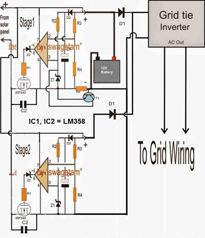
Referring to the above grid, solar panel optimizer circuit, we can see two basic identical stages using two opamps.
The two stages are exactly identical and form two parallel connected zero drop solar charge controller stages.
The upper stage1 includes a constant current feature due to the presence of the BJT BC547 and Rx. Rx may be selected using the following formula:
0.7x10/Battery AH
The above feature ensures a correct charging rate for the connected battery.
The lower solar charge controller is without a current controller and feeds the inverter (GTI) directly through a series diode, the battery also connects with the inverter through another individual series diode.
Both the solar charge controller circuits are designed to generate the maximum fixed charging voltage for the battery as well as for the inverter.
As long as the solar panel is able to receive peak sun light it overrides the battery voltage and allows the inverter to use current directly from the panel.
The procedures also allows the battery to get charged from the upper solar charge controller stage. However as the sun light begins depleting the battery overrides the solar panel input and supplies the inverter with its power for carrying out the operations.
The inverter is a GTI which is tied with the grid mains and contributes in sync with the grid. As long as the grid is stronger the GTI is allowed to be sedentary which proportionately prevents the battery from getting drained, however in case the grid voltage drops and becomes insufficient for powering the connected appliances, the GTI takes over and begins fulfilling the deficit through the conneced battery power.
Parts list for the above solar, grid optimizer circuit
R1 = 10 ohms
R2 = 100k
R3/R4 = see text
Z1,Z2 = 4.7V zener
C1 = 100uF/25V
C2 = 0.22uF
D1 = high amp diodes
D2 = 1N4148
T1 = BC547
IC1 = IC 741
R3/R4 should be selected such that its junction geneartes a volatge which may be just higher than the fixed refernce at pin2 of IC1 when the input supply is just over the optimal charging level of rthe connected battery.
For example suppose the charging voltage is 14.3V, then at this voltage R3/R4 junction must be just higher than pin2 of the IC which may 4.7V due to the given zener value.
The above must be set using an aritificial 14.3 V external supply, the level may be changed appropriately as per the selected battery voltage


Questions & Answers
Hi Swag,
Which modifications can one make with regard to the above circuit if the ongrid inverter is 24 volts dc and secondly if its 48 volts dc. Also will the circuit work as it is for the 12 volts dc system for offgrid solar inverter, same applies for off grid 24 volts dc and 48 volts dc. And which modifications will one have to make if any for optimizing the off grid system.
Hi Bernard, the above circuit was designed a long time ago, and upon reviewing I find that the design has some problems, which needs to be corrected….If possible I will do it soon and respond to your query….
Hi Swag
Thank you very much Swag. Please in your corrections can you kindly give suggestions for 24volts dc as well as 48 voltd dc.
Hi Bernard, I have corrected the diagram, you can use 24V panel also in this diagram, however 48V may not be possible in this design…
Hi Swag
Thank you very much for the feedback.
Regards
Bernard Tendengu
You are welcome Bernard!
dear sir
i have a 20w solar panel and 12v 26amp battery so which is the best charger for me please suggest me sir
samir…
Dear Samir, please specify the current rating of the panel also so that I can analyze it correctly.
I have a charger control in the middle I have seen in one of your answers about how to make charger control which when there is sun the batteries uses the solar direct when there is no sun I can use the batteries. The inverter is 24 volts pure sine wive .if you can give me a link to the diagram I will be grateful
you can try the idea presented in the following article
https://www.homemade-circuits.com/2012/10/solar-panelac-mains-relay-changeover.html
ignore, or remove the bridge power supply and the LM317 stage, and modify the design as follows:
connect the pole of the relay with your battery positive, connect the negative with the circuit negative and the solar negative (in common)
next, connect the N/C with load which may be an inverter.
this will provide you with the intended function.
make sure to adjust and set the preset for cutting off the relay at the desired low sun shine level.
hi i have 650 watt solar panels and 8 100Ah batteries using them to power transmitter and stl machine.
am not sure if i have done the wiring correct due to the fact that when the sun goes down the batteries goes empty
you'll need a charger controller in the middle for implementing the operation correctly and optimally….
Dear Swagatham, My search for a circuit brought me here, very interesting blog. I need your help to find a problem in Solar panel connection. We have solar panels with micro inverters attached to it, so the output from the array is AC, this line is connected to the grid at the distribution box. Micro inverters function only when there is power in the grid. Unfortunately our grid is not at all reliable. We thought of introducing a conventional line interactive home inverter in between the grid and PV supply. When ever the grid fails the inverter switch on so the PV supply continue.
The issue is, chance of power flowing into the inverter from PV in case the load is turned off at home. We need the back up from the home inverter for the night time emergency.
Seeking your advice.
Dear Manoj, you can probably try including a relay changeover design in between the inverter and the mains, as described in this article:
https://www.homemade-circuits.com/2012/09/automatic-inverter-supply-and-mains.html
sir, whether this circuit has been tested keberhasilanya and father can explain the workings of the line?
It's not been tested but will surely work, as per my simulation.
dear swagatham majumdhar sir will you please design me an hybrid inverter circuit for me
the inverter should have the following features
1. it should be microcontroller based pwm hybrid inverter
2. it should be compatible for 24v batteries and 12v batteries also
3. if solar power is available it should take power from solar panel
4.it should charge from solar panel
5. if no solar power available it should use battery
6. if battery voltage is below 70% it should use the ac power to charge it untill battery voltage reaches 70%
and use ac power for inverter while charging
please design me the circuit for me
THANKS IN ADVANCE
please notify me when it is done sir
Dear Naveen,
Designing a MCU based inverter will be difficult, i am not good with coding and stuff, so sorry can't help with this project.
Hi Mr.Swagatam..
I want to ask you in order to make my understanding about a variety of "How to make Solar Sharge Controller". because until now, i'm still confusing to make a simple one with/without a copy of circuits on the internet.
I try to understand of work of Comparator to make a Lead Acid Charger from Solar panel.
Last night i was make a new simple one. with Dual Op-Amp Comparator LM358 and trigggering the P-Mosfet IRF9540.
the Circuit Idea is below:
https://drive.google.com/file/d/0B6YhcDN9vKrDSGJmNzFaUHIwemM/view?usp=sharing
After I make this one, not on breadboard but the dot matrix PCB. I powered up still by 30A Transformer Linear Power Supply that i have. i try to tune the Trimpot in BATT SENSE circuit, but the lead of it's sense i put it on (+) of Power Supply. then i tune the voltage of my power supply to make sure my circuit is working or not. I will cut off the voltage, when the SENSE is 13.8V. with my Digital Multimeter, I have this parameter :
(On Charge of Red state LED)
Pin 3 : 3.96V
Pin 2 : 3.22V (and increase with higher voltage too so i think it's normal)
but when charge state switch to Float. I have this parameter :
(On Float or Green state LED)
Pin 3 : 3.70V (why this voltage is down from charging voltage? are my circuit is wrong?)
Pin 2 : 3.98V ~ 4.01V (Higher that ref. voltage on pin 3 then trigger Mosfet off)
I think i was done to make this circuit. then i rearrange that, put the BATT SENSE to the battery, with load of my 45AH MF-Battery and try to charge that. LED going to RED and Charge is working now. I have my mosfet get little warm and Scottky diode have warm too (okay it's working). but when the Voltage battery has reaching the Cut off voltage (13.8V) the state LED won't switch. I don't know what happen. so i measure the pin 3 and pin 2 with my Multimeter, and something weird happen, when i touch the Pin 3 with the tip of my (+) probe DMM, LED has change to GREEN and Mosfet going off. but when i put it on Pin 2, the RED led glowing again and Mosfet is going to work for Charge again. (i feel it's like a tray pulse from my multimeter to grounding or something). this phenomena is happened too when i try to make a Charger circuit with NE555 timer too. still when i try to measure the Pin of IC,(pin 2 and pin 6 of NE555) and when the circuit is not standalone working, every touch of (+) Probe of my DMM is like make some "trigger".
could you help me with my problem?
Thank a lot before.
regard.
Dhyaksa Hada N.
Hi Dhyaksa, your circuit is correct and will work, but the lower opamp is not required, just remove it to avoid confusions.
You can add the LEDs across the output of the upper opamp as shown in the following example circuit and get the intended indications correctly.
4.bp.blogspot.com/-LcjRsOsnA9A/UUvm_gxwwsI/AAAAAAAADuc/LYGQ5gpFB_w/s1600/6v+4+ah+battery+chager+circuit,+12v+input.png