If you feel strobe lights very interesting but are disappointed by the fact that these wonderful light effects can be produced only through complex xenon tube then probably you are quite mistaken.
It is very much possible to make any light a strobe light if you are equipped with a proper driving circuit capable of handling different lighting devices to generate the desired strobe light effect.
The present article shows how a circuit as basic as a multivibrator may be modified in different ways and made compatible with ordinary bulbs, lasers, LEDs to produce spectacular light pulses.
A strobe light may be used for warning, scientific analysis or as an entertainment device, whatever may be the application the effects are simply dazzling. In fact it is possible to make any light a strobe light through a proper driving circuit. Explained with Circuit Diagrams.
Difference Between Flashing and Strobing
A light when made to blink or flash indeed looks pretty eye-catching and that’s the reason why they are used in number of places as a warning device or for decorations.
However a strobe light in particular may also be considered a flashing light yet is uniquely different from ordinary light flashers. Unlike them in a strobe light the ON/OFF pattern is so optimized that it produces sharp dazzling pulsed flashes of light.
There’s no doubt why they are mostly used in conjunction with fast music to enhance a party mood.
Nowadays green lasers are being popularly used as a strobing device in party halls and gatherings and have become hot favorite among the new generation.
Whether it’s LEDs, lasers or an ordinary filament bulb, all can be made to flash or rather strobe using an electronic circuit capable of producing the required pulsed switching in the connected lighting element.
Here we will see how we can make any light a strobe light using a simple electronic circuit.
The following section will acquaint you with the circuit details. Let’s go through it.
Pulsating any Light to Produce Strobing Effect
Through one of my previous articles we came across a nice little circuit able to produce interesting strobe effects over a few of the connected LEDs.
But this circuit is only suitable for driving low power LEDs and thus cannot be applied to illuminate big areas and premises.
The proposed circuit allows you to drive not only LEDs but also powerful lighting agents like incandescent bulbs, lasers, CFLs etc.
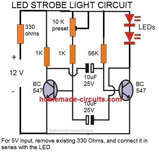
The first diagram shows the most basic form of a multivibrator circuit using transistors as the main active components. The connected LEDs can be made to strobe by suitably adjusting the two potentiometers VR1 and VR2.
UPDATE:
I have explained a few transistorized strobe light circuits in this article, however the below shown design is the easiest one and is tested by me. So you can begin with this design, and customize it as per your own preference and liking.
Video Illustration
The above discussed simple design can be further modified as I have explained below for greater control and refined outputs.
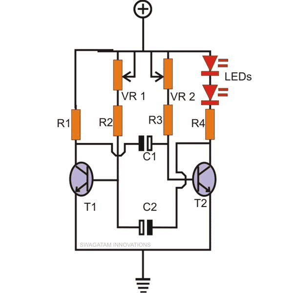
The above circuit forms the base for all the following circuits through some suitable modifications and additions.
Using a Flashlight Lamp as Strobe Light
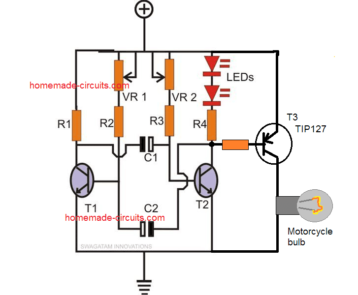
For example if you want to illuminate and pulsate a small torch bulb using it, you would just need to do the simple modifications as shown in the second diagram.
Here by adding a PNP power transistor and triggering it through the collector of T2, a torch bulb is easily made to strobe. Off course, optimum effect is achieved only through proper adjustment of the two Pots.
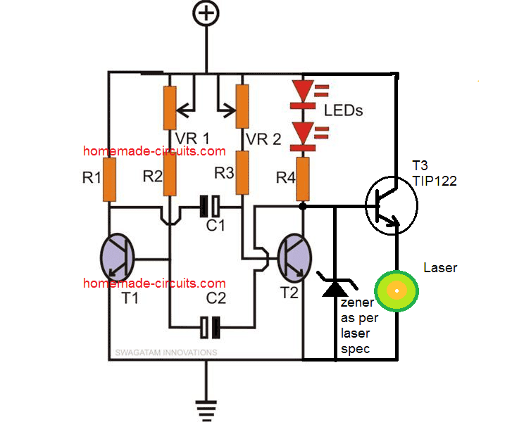
As already discussed already in the previous section, green laser pointers are pretty popular nowadays; the diagram illustrated shows a simple method of converting the above circuit into a pulsating green laser pointer strobe light.
Here the zener diode along with the transistor works like a constant voltage circuit ensuring that the laser pointer is never supplied with a voltage higher than its maximum rating.
This also ensures that the current to the laser can also never exceed the rated value.
This the zener and the transistor functions like a constant voltage and also an indirect constant current driver for the laser.
Using AC 220V or 120V Lamp as Strobe Light
The next diagram shows how an AC mains lamp may be used as a strobing light source using the above circuit. Here a triac forms the main switching component receiving the required gate pulses from T2’s collector.
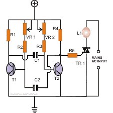
Thus we see that through the above circuit designs it becomes very easy to make any light a strobe light simply by doing the relevant modifications within a simple transistor based circuit as exlained in the above examples.
Parts List
- R1, R4, R5 = 680 Ohms,
- R2, R3 = 10K
- VR1, VR2 = 100K pot
- T1, T2 = BC547,
- T3, T4 = BC557
- C1, C2 = 10uF/25V
- Triac = BT136
- LEDs = as per choice
Police Strobe Light Circuit
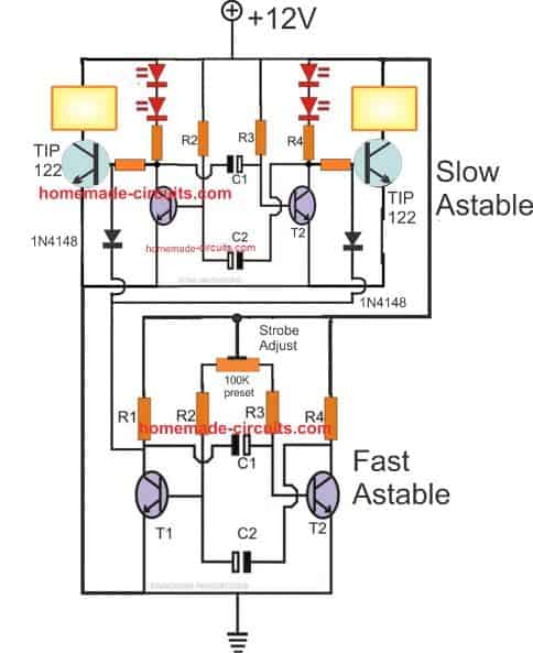
For the slow astable use the following parts:
- R1, R4 = 680 Ω
- R2, R3 = 18K
- C1 = 100 μF
- C2 = 100 μF
- T1, T2 = BC547
For the Fast astable use the following parts
- R1, R4 = 680 Ω
- R2, R3 = 10K
- preset = 100K
- C1 = 47 μF
- C2 = 47 μF
- T1, T2 = BC547
36 Watt Current Controlled Strobe LED Light
This 36 watt LED strobe light circuit with current control feature was requested by one of the dedicated readers of the website, Mr. Rohit.
The design idea can be learned from the following explnation:
I am trying to make a fast flash LED strobe light like the ones used by cameramen for photography. I have seen some circuits on your website regarding LEDs like constant current driver, powering high wattage LED lights, LED strobe light. However, I think my application is a combination of these projects.
So what I want to do is power 18W or 36W LEDs for 1 microsecond flash and need a constant current driver so that every flash has the same intensity.
I hope to hear from you soon. Feel free to contact me if you have any questions by email or call me to discuss further
The complete circuit diagram for the 36 watt high power LED strobe light with current control feature can be witnessed in the following image:
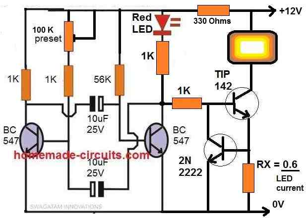
Parts list
- All resistors are 1/4 watt 5% unless specified
- 1K = 4nos
- 330 ohms = 1no
- 56K = 1no
- 100k preset = 1no
- RX = as given in the diagram
- Capacitors
- 10uF/25V Electrolytic = 2nos
- Transistors
- BC547 = 2nos
- TIP142 = 1no
- 2N2222 = 1no
- RED LED = 5mm 20mA type
- PowerLED = 12V, below 5 amps.



Questions & Answers
I got a few questions for you. I am a volunteer fireman and I'm thinking about using your design here for some emergency lighting for my jeep. How could i wire in 2 strips of LEDs both containing 6 LEDs, and make them alternate? Also can this circuit work on a 12v DC circuit?
If you can email me about this I'm very interested in learning more.
The above circuit will work with 12V supply.
You can use the first circuit with the following mods:
Connect LED on the other arm also but use three LED in the series.
You can accommodate another series of 3 on each arm with separate individual series resistors as done with the previous series, in this way you have six LEDs on each side.
If you have readymade strips with the above series built in, you can simply connect each strip directly between the collector and the positive of the transistor on each arm..R1 and R4 will not be required in that case.
he parts list would be:
R1, R4(for the first option) = 150 ohms
R2, R3 = 68K (the VR1/2 are not required, you can remove them and connect R2 R3 directly with the positive rail)
Capacitors = 10uF/25V
Transistors = BC547
Hi, I followed your first circuit diagram on a breadboard and it worked perfectly. I'm truing to make a 12v circuit using 12 festoon LEDs with inbuilt resistors. I can't quite work out from your written description what to do. Can you draw it?
Hi, if the LEDs are rated to work with 12V, you may connect 6 of them in parallel across each transistor collector arm, they should work, but the transistor may need an upgradation and may be replaced with 8050
Hi Swagtam, OK, getting closer. My previous post probably didn't accurately describe what I'm trying to do. I have a vehicle 12v festoon LED bulb that I want to rapidly blink. I originally didn't understand what you meant by connecting between collector and positive (I thought you meant the positive base of the transistor, and blew it up) but understand now that you meant the positive rail at the top of the circuit.
OK, so I have removed R1 and R4. R2 and R3 are still the original 10k ohm resistor and the trim pots are still there at 100k ohm. I wired in the 12v LEDs where the original 3v LEDs are in the 1st circuit. Now I get the LEDs to light up, and dim slightly with a tweak of on of the trim pots, but no blink.
Should I take out R2 and R3? Should they be replaced with a smaller ohm resistor? One last piece of info is that the 12v festoon LEDs measure 88.7 ohms across.
Any help would be appreciated.
Adam
Adam, yes making R2/R3 smaller will produce faster blinking rates so you can try replacing them with 1k resistors.
If the LEDs are not completely shutting off, the reason could be leaky caps or wrongly connected cap polarity.
If the caps are OK, you may try adding a series 50 ohm resistor with the LEDs to eliminate the issue or put 1N4007 diodes in series with the emitters of T1/T2
I'm an amateur with dc electrical circuits but quite fascinated and eager to try. I have been throwing around the idea of trying to build an electric fence charger. I think your strobe circuit would work. Would you agree? I need a constant on/off/on/off power source capable of delivering a high voltage shock while still not being strong enough to deliver permanent damage. These are the specs on a 2 mile fence charger.
Item Specifications:
115 volt, 60 cycle
AC input/output
0.5 joule output
Pulsed output
Output voltage no load is 2300 volts
2 mile range
I would like to build a tiny fence charger that would energize only about 50 ft. What do you think…is it possible?
Yes the above circuit can be used with a fence charger for triggering short pulses, I have discussed one similar application which employs a 555IC producing identical results which also has an adjustable pulse rate feature, you can refer to the following two articles for getting an idea regarding the concepts:
https://www.homemade-circuits.com/2012/05/make-this-solar-powered-fence-charger.html
https://www.homemade-circuits.com/2011/12/homemade-fence-charger-energizer.html
….for making it tiny you can replace the ignition coil suggested in the above links with a small ferrite core transformer as used in mosquito zappers.
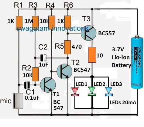
Hi, the third circuit would perfectly suit your need. LS1 may be replaced with the LED,
T4 = 2N2907
T3 = TIP32
R6 = 0.6/0.5 = 1.2 ohm it's the current limit for limiting the current to 500mA
rest everything would be as per the given parts list.
….T1, T2 = 2N2222
Hello
Just came across your blog. Are these circuits free to use or there are any copyright issues???
Hello, Practical use is free and allowed, but publishing elsewhere could be an infringement
Thanks and it worked great..how to make them to blink twice one and twice other if we connecting them on other arm as you said above in comment?
For blinking it twice on each channel you may have to build another identical circuit, but without the collector resistors.
connect the collectors at the junction of the respective resistor and LED of the on each channel of the previous circuit.
adjust the new circuit to blink faster so that two blinks are injected on the LeDs.
…make sure the resistor of the LED is connected with the positive and the LED with the collector for implementing the above integration.
if you have the LED connected to positive and resistor to the collector, just swap the positions.
Hey bro when i connected this circuit the led is not blinking instead glowing steady also bc547 gets heated much
What should i do?also is it ok to replace the two led with led strip?
led strips rated to work on 12V can be connected with the above circuit, change the transistors and check again, it seems the transistors are blown, replace them with 2N2222 or 8050
Yeah u r ryt it blown out…now works perfect as per ur diagram but brightness is low wt to do for it?i hv replaced two led and 680ohms into led strip..whats advantage of 2n2222 and 8050?how to check blown transistor? Btwn thnkz a lot finally my bike blinking:-)
LED strips already have internal resistors so may be R1, R4 can be eliminated from the circuit.
2N2222 or 8050 are have higher current rating will not become warm or get damaged with higher current or voltages.
…..2N2222 or 8050 have higher current rating therefore will not become warm or get damaged with higher current or voltages.
R1too it won't affect ics?btwn does it is reduce the brightness of the led due to less current? I already removed r4.. Does it works on 24v circuit too? Thnkz for the kind reply 🙂
sorry No, if you are using only the R4 channel then you should NOT remove R1 otherwise T1 will blow off.
yes you can 24V also but only if the strips are also rated at 24V
Cool super works by u 🙂 can u lend me ur email id i have some queries and i need to send pics?
thanks Bro! here's my email ID hitman2008@live.in
Hey i tried 1st one and works perfect on 9v battery and if i connect them in my bike the bc547 gets heated and no blinking in bulbs..
use 1k for R1, R4 and if possible replace the BC547 transistors with 2N2222….
Please give a suggestion..
I'm interested in flashing an LED 80-100 times per second. How can I accomplish this? Thank you!! jasona111988@gmail.com
reduce C1/C2 and VR1/VR2 values…
I've noticed that some strobe circuits are better than others. Better, I mean sharper transient response. I'm looking at the kind used in the strobascope applications. https://en.wikipedia.org/wiki/Stroboscope
I've created art using this concept and tried various strobes. The conventual novelty units work best, cell phone stobe apps do not. They seem to blur the visuals the conventual are crisp.
Can you tell me why and also point me in the direction of concept to make a working circuit with sharper transient response?
Thanks!
Did you try a simple PWM IC 555 based stroboscope circuit? or you can also try a NAND gate PWM circuit for generating absolutely sharp turn ON/OFF strobe effects
the pulse width can be controlled through the shown pot, and the frequency by changing the capacitor values.
Hi! i´m try to use this for an OFF/ROAD led cubes in my vehicle andmanage to make it work eleminating "R4" but still the leds do not illuminate to their maximun capacity and sometimes they stop being strobes, these led cubes are 12v but do not specifies the watts, Iknow they are hig wattage, could you please help me with this dilemma? thanks in advance
I use 1/2w resistance
Please try the second circuit from top, replace the bulb with your LED, but make sure to add a calculated resistor in series otherwise your LED and the PNP transistor both might get damaged
you can also try the third circuit from top
T3 should be TIP127 or as per the LED current
HI, finally I know that the LED cubes are 12v 18w and i´m going to use two LED cubes, if I use the second circuit with the "TIP127" is going to work?
Hi, yes you can use the second circuit for getting the intended results.
use a large heatsink for TIP127
Hii sir, I am interested in using your circuit for speed measurement( Application of Stroboscope) so will it work for flashing light at high frequency and provide sharp light pulses at variable rate I.e at 0.5 ms to 100 ms? Please It'll be so kind if u can help me…
Hi Yakub, yes it will definitely work…you can try the second design from top….make sure to connect a 1N4007 diode in series with the emitter of the PNP transistor to ensure total switch OFF of the connected lamp
Hi Sir, I am a begginer in this and don't even know about the symbols or short forms of parts used in the schematic diagram. So, please kindly help me in this. I am interested in making a simple Led strobe with simple parts. So plz sir kindly send me circuit diagram with full names of parts and their values. Bcoz i can't understand above circuits of strobe lights.I will be very thankful to you for helping me.
Hi Anshuman, here's the parts list for you
Parts List
RESISTORS, 1/4 WATT
R1, R4, R5 = 680 Ohms,
R2, R3 = 10K
POTENTIOMETER
VR1, VR2 = 100K pot
TRANSISTORS
T1, T2 = BC547,
T3, T4 = BC557
CAPACITORS (ELECTROLYTIC)
C1, C2 = 10uF/25V
Triac = BT136
LEDs = as per choice
Hello,
Which of this circuit well power 12v LED to use as signal blinker for a motorcycle? And as replacement for my broken flasher in my motorcycle?
Thanks..
Paul
you can use the second circuit for your purpose, replace the bulb with your 12 LED connections
Thank you very for the quick response
Thank you for helping us newbies..
Paul
you are welcome Paul!
BTW Sir,
In the second circuit can i add a piezo buzzer? And can i remove the two leds connected at R4?
Thanks again.
Paul
yes you can remove the LeDs, and also add a buzzer in parallel with R1 or R4…the buzzer should be a piezo buzzer ready to use