In this RGB spotlight mixer circuit project, 3 individual spot lights are used, having red, green and blue focus light bulbs in them. The lights can be focused on walls, ceilings or floors to create interesting slow rising, slow fading red, green blue light patterns that mix and diffuse to generate interesting, additional secondary colors.
Contributed By: Antoine de Lafayette

The intensity of the RGB lights slowly increase and decrease, as per the settings of the individual focus lights, which causes the ficus outputs to change color like a chameleon does, very slowly and subtly with different time constants, producing multitude of different colors shades and themes, on the surface where the lights are projected.
- Red + green + blue = white
- Red + green = yellow
- Green + blue = cyan (green-blue)
- Blue + red = magenta (purple)
- Yellow + blue = green
- Cyan + red = white
- Magenta + green = white

Circuit Description
The basic idea here is to chop the AC supply to the specific RGB lamps at some predetermined rate, such the glow on the lamps slowly brighten and slowly dim, generating interesting color blends and intriguing complex color bands around the focused areas.
Referring to the RGB spotlight mixer circuit we can see 3 identical stages, each comprising of a IC 555 astable sawtooth generator stage, an intermediate BJT amplifier stage, and a triac lamp driver stage.
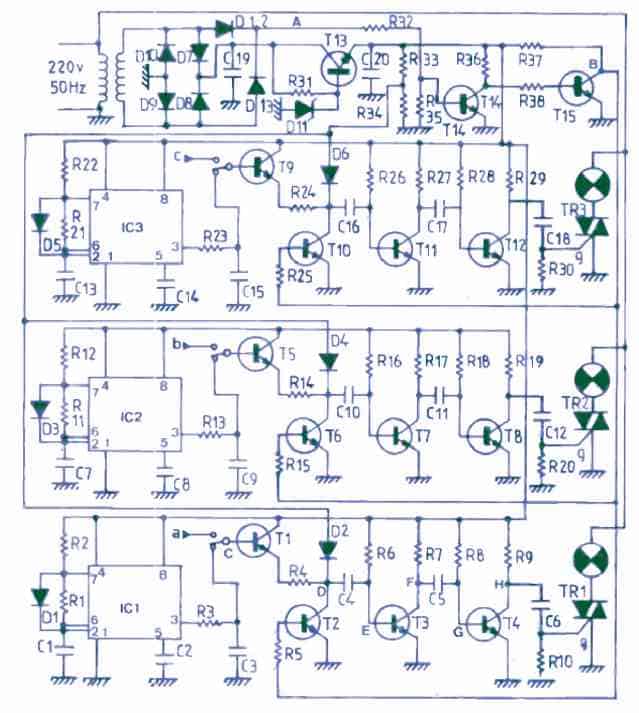
The function of all the 3 IC 555, BJT amplifier and the triac lamp driver stages is the same. The IC 555 ICs are all rigged as astable which has a sharp and fast charge time but a slow discharge time due to the inclusion of the diode across pin#7 and pin#6/2.
This generates very long ON time, and short OFF time at the respective pin#3 of the all the 555 ICs.
The OFF time outputs at the pin#3 of the ICs are in the form of a momentary pulse, which is applied to the bases of the respective BJTs T1, T5, T9, which are configured as emitter followers.
With ON/OFF pulses from the pin#3, causes the emitter follower transistors to be activated accordingly, generating a corresponding level regulated voltage across their emitters.
This emitter voltage from the emitter followers BJTs is applied as an interrupting potential across the transistor buffer stages built around T3, T4, T7, T8, T11, T12.
We can see that the first transistor from these buffer stages, that is T2, T6, T10 are pulsed at the 50 Hz rate from the transformer AC via D12. This 50 Hz pulses causes the all the 3 triac lamp drivers to be operated with a constant level of illumination, only as long a the IC 555 pulses are not available.
However, with the interruption caused by the IC 555 pulses, buffer stage transistors are forced to create a specific chopping waveform that are incrementing and decrementing in nature.
This incrementing and decrementing chopping pulses causes the triacs to switch the AC across the connected RGB lamps, with gradually increasing and decreasing ON/OFF times across all the 3 triacs.
As a result the RGB spot lamps focus color slowly and automatically become brighter and dimmer, creating interesting color mixing of the red, green, blue illuminations, focused on a specific surface.
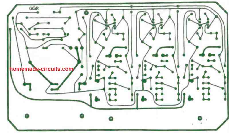
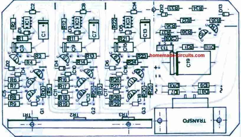
PCB Design
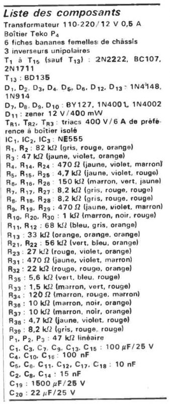
Parts List

Need Help? Please Leave a Comment! We value your input—Kindly keep it relevant to the above topic!