In this article I have explained a simple single IC LED tube ligt circuit applicable for 110V/120V AC inputs. The circuit uses 30 numbers of 1 watt LEDs, and also includes a voltage and current control features.
In my previous post I discussed the IC TL783 which is a 1.25V to 120V variable DC regulator IC. We learned how this IC could be configured for acquiring the specified adjustable outputs.
Here we employ the same basic configuration for making a simple 120V compact current controlled LED tubelight circuit.
Circuit Operation
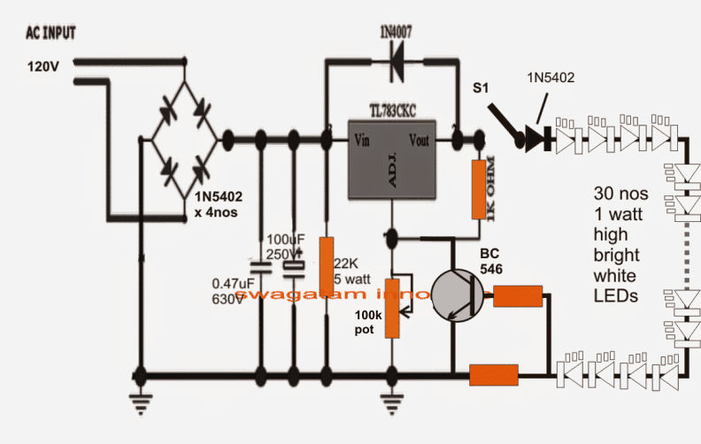
Referring to the 120V compact tube light circuit shown below, we can see the fundamental design incorporating the IC TL783 with the addition of a current control stage made around a single NPN transistor BC546.
30 nos of 1 watt high bright LEDs can also be seen connected across the output of the circuit. All the LEDs are connected in series.
The transistor BC546 along with its base/emitter 2 ohm resistor forms a classic current control stage.
It ensures that the current to the LEDs can never exceed the 300mA limit, which is quite enough for providing an optimal glow over the LEDs.
Before connecting the LED string to the circuit output via the switch S1, the 100k pot should be adjusted to produce exactly 100V across the specified output terminals of the circuit, before or at the left of S1.
Once this voltage is ascertained, S1 may be pressed ON for integrating the LEDs with the circuit.
The above setting ensures that the LEDs are subjected to the correct 3.3V per LED spec and at a current of 300mA.
20 Watt is Equal to 40 Watt
The overall illumination level of this 120V compact transformerless tubelight circuit would be equivalent to a 40 watt fluorescent tubelight.
The 100k pot could be also used for reducing the brightness of the "tubelight", however be sure you don't accidentally increase the voltage above 100V...although this won't damage the LEDs due to the current control feature being present, it's not recommended.
The IC TL 783 will require a good heatsink for enabling optimal results.
This circuit cannot be used in countries with 220V AC Mains specification.
Circuit Diagram
Warning: The circuit I have explained below is not isolated from mains AC, and therefore are extremely dangerous to touch in the powered and open condition. You should be extremely careful while building and testing this circuit, and make sure to take the necessary safety precautions. The author cannot be held responsible for any mishap due to any negligence by the user


Questions & Answers
If the 120v supply is grounded, are the two circuit grounds (earths) also needed? If so, where should they ground?
Thank you,
Erwin Williamson
The 120V is not grounded anywhere. The 120V is only applied to the bridge rectifier. The ground symbols refer to the common 0V line of the bridge rectifier (-) output.
Dear Sir,
what change I should make if I want 9W 110V screw type LED bulb ?
Hello Amitava,
You will need to adjust the 100k preset (not pot) so that the output voltage after the 1n5402 diode generates a voltage that matches the total forward voltage of your series connected LED.
So first determine how many LEDs you want to use which corresponds to 9 watt output, then assuming the forward voltage drop of each LED is around 3.3 V, multiply this 3.3V with the total number of LEDs, this will be the output voltage which you will need to set using the 100k preset.
Hi Swagatham,
You have many interesting circuits here Sir. This is the circuit what I need.
On the transistor base/ emitter resistors has no value displayed. Are these 2 Ohms both and how many watts should be?
I have 2 LED stip lights 120volts 20W non dimmable and i like to make it dimmable.
Checked voltage and current at LEDs 70 Volts DC and 0.24A one strip has 120LEDs.
I removed the balance circuits and connected the strip light series. This is what I working on it now.
Best regards,
Attila
Thank you Attila! The lower resistor can be calculated using the following:
R = 0.6 / max LED current
the upper base resistor can be a 100 ohms 1/4 watt
the wattage of the lower current limiting can be calculated using th formula: R = 0.6 x max LED current
Yes you can use your 70 V LED strips with this circuit, just make sure to set the power supply voltage 70V before connecting, and calculate the current limiting resistor appropriately
Hi Swagatham,
I feel so close to you by often seeing your page reading all comments . I did some of the circuits and working. i have a doubt regarding this 110v tube circuit,can two of these circuit be connected in series.
Have a good day.
Thanks and Regards,
S.Jayaprakash.
Thank you Jayaprakash!!
I am not very sure about the results, technically it sounds correct but still it will need to confirmed practically
It's worth trying though if you don't mind burning a few of these ICs in case it doesn't work:)
hi sir thanks for fast rply
sir to provide 110v ac for above circuits can i use simple DIAC TRIAC convertor which we also using in electronic fan speed regulator
Hi Vaibhav,
It could be risky because the IC circuit could present a low resistance for the dimmer and blow the triac, or short-circuit it damaging the IC circuit
Dear T.Ray,
If we use capacitor or resistor that will result in reduction in current which will make the above circuit purpose useless, if we employ higher uF then that could cause initial high current surge and damage to the IC….therefore it's not feasible.
hi sir thanks for this inovative circuit
sir r you cheked this circuit practically
Hi Vaibhav,
I have not checked it, but since it's as per the datasheet of the IC it should work.
Hi,
As you said, white leds are available with any retailer in hyd. OK
Is ther any bother about wattage? should we consider it? how can I know wattage?
As you said, R= (supply vg – forward vg) / current. for lihting a led.
how can we know the current exactly for optimal light without break of led.?
we can know forward vg by multimeter.
wattage is specified by the manufacturer for individual LED types, the retailer will know about it provide with the correct wattage types as per your requirement.
You can verify the same by checking its image online, and by viewing the datasheets of the particular type on the net.
thanks, let's hope we get an appropriate chip for 220v as well
hi swagatam,
What is the easiest way to build an smps. I need 110v,35v,26v dc/800ma power supply. Is there any general idea in designing smps. Cheap smps are similar to mje13001 charger circuit, some SMPS designs use BU508 as hot, and a small pwm/multivibrator is used to control hot.(like joule thief, in reduction). Do you have any custom-made smps circuit designs?
Hi Max,
There's no easy way of building an smps…the easiest way is to probably buy one readymade piece from the market and modify the output winding of the trafo for getting the required voltage outputs.
I have discussed one simple diagram in the following article, it's probably the simplest and with all the necessary details:
https://www.homemade-circuits.com/2013/10/12v-24v-1-amp-mosfet-smps-circuit.html
begin with learning about resistors first, regarding identifying their values through color codes, series/parallel connection methods, same for capacitors also….then gradually go for other components and try to grasp their working details.
Hi Mr Swagatam
How to make this for 230v, please
Hi Kapila,
unfortunately we don't have a similar 220v chip yet….
simulation softwares don't always provide correct results and are not credible enough so they cannot be trusted.
a novice should obviously start from the basics first and upwards.