In this post I have explained to make an active loudspeaker system circuit for enabling self sustained amplification of any music source that may be directly plugged in to the active speaker box.
Introduction
With the advent of ultra modern cell phones, now it has become possible to store huge music data and listen to them with just a flick of your finger. But listening to music becomes significantly pleasing only if it’s hugely amplified and reproduced over active loudspeakers or with systems incorporating a speaker amplifier circuit.
By amplifying a small music signal from either a cell phone or similar source and hearing it over active loudspeakers can become more interesting and the outcome simply amazing. Complete design idea and schematic of a simple speaker amplifier is produced here.
A normal loudspeaker may be a 3-way type with the connected amplifier equipped with the usual bass treble controls etc. No matter how good they may be in their performance, they can never beat the sound quality that is normally achieved through active loudspeakers. Whether it’s by quality or power they are the best sound reproducing gadgets.
Building an active loudspeaker system may look complex but can be very amusing, and once built can indeed become a treat hearing its magnificent response.
Although the cost involved compared to its passive counterpart is much higher, an active system has definitely a clear edge over the passive systems.
Advantages of Active Loudspeaker System
The various advantages of a built in speaker amplifier over the passive design may be listed as follows:
No external amplifiers required and so no cumbersome wiring involved.
No use of passive filter circuits using resistors and inductors means an increase in the overall efficiency of the output response due to the absence of power losses through heat dissipations generally involved with passive filter resistors.
Unlike passive filters, the active filters help to boost the set responses. With passive filters it’s just the opposite, they tend to make the input music response deteriorate to a great extent.
Here I will elucidate one such active loudspeaker circuit, capable of transforming even an ordinary music inputs into outstanding reproductions. Let’s read its circuit details.
Circuit Operation
The following points will discuss one such speaker amplifier circuit, capable of transforming even an ordinary music inputs into outstanding reproductions.
The idea is very simple, equalize the inputs by passing them through appropriate lo-pass and hi-pass filters at the input stages, then amplify this dimensioned content to suitable high volumes using ordinary amplifier.
We do exactly as mentioned above; referring to the figure we find that a single IC TL072 which is basically a dual op-amp in a single package is discretely configured into two separate filters.
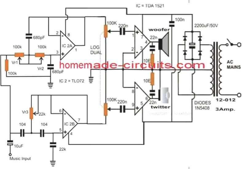
IC 2A is wired as a standard high pass filter. As the name suggests, the circuit will pass only specified degree of high input frequencies. The cut off frequency may lie around 3 kHz and can be varied by adjusting VR1 and VR2 or any one of them.
IC 2B is wired in just the opposite configuration i.e. as a low pass filter and allows only the specified degree of frequencies iver the lower ranges, the cut off frequency being 2.5 kHz. It will stop all frequencies above this. The response is adjustable using VR3.
The above suitably equalized audio now is simply fed to an audio amplifier for the required amplifications over the connected loudspeakers.
The channel responsible for producing higher frequencies uses a twitter for better optimization where as the other section which handles the lower frequencies is integrated to a woofer for the relevantly bass output optimization.


Questions & Answers
Hi. I have an active subhoover speaker came with the soundbar 5.1 ch. Now soundbar system not working, however I want to make use of the speakers because I believe they should be working fine. How do I go about this, any ideas sir?
In this situation you may have to open the subwoofer box and check whether the amplifier circuit is working or not, if yes then you can use the system to amplify music from your mobile phone. If the amplifier is not working then you can discard the amplifier section and use only the speakers with an external subwoofer amplifier unit.
I have an old Sanyo S5 Speaker, problem is it has One Tweeter, One Woofer but there seems to be no Power Cord, I am scared if I use unwanted power cord to give power to this unit. Please send me reply on this as I would like to make this Loudspeaker as Bluetooth with proper power cord to get proper music from any devices including Cellphones etc. my email address is:
catchsadanand@rediffmail.com
I also dont have circuit diagram for this speaker, so please post me as much information as possible so I can repair & reuse these speakers without additional cost.
Thanks
I understand your problem, however, sorry, I do not have any details about Sanyo SS speaker systems.
Good day sir. I am new to electronics, but I am also fascinated by audio amplifiers. I have collected a few old car stereos and was wondering if I can use the power amp circuit to make an amplifier? I have downloaded the data sheet for the ic, however i do not know what to so with the mute and the standby pins. where do I connect these and how do I power up the circuit?
Hi Roberts, yes you can use the TDA1521 IC to build a nice little 12+12 W amplifier circuit. I tried to learn about the standby and the mute pins in the datasheet, but I could not find any such pins available on the IC??
Hi, Surely the circuit as drawn is (nearly) correct and the woofer and Twitter are connected to the correct outputs. The problem is that you have said that the IC2A circuit is a high pass filter when in fact it is a LOW pass filter. Similarly IC2B is not a low pass filter but a HIGH pass filter so its output correctly goes to the Twitter. Also I think that the 22k "capacitor" going from pin 5 of IC2B should be a 22k RESISTOR as per the the standard 2nd order high passactive filter circuit. Please comment
Thanks, You are absolutely right, it seems I did not concentrate on the diagram while replying the previous comment from marife..
Hi Sir, correct me if i'm wrong, you have mentioned above that IC 2A is wired as a high pass filter yet it was feed to a woofer at pin#4 and IC 2B wired as a low pass filter and was feed to a twitter at pin#6. Should i interchanged the two driver?
Hi Marife, yes it's a mistake, just swap or interchange the woofer and the twitter positions for correcting the fault.
Hi Sir, in the diagram above what is the correct value of capacitor connected across ground and pin 5 of TL072? it was indicated as 22k, thank you.
Hi Marife, it should be a 0.022uF
Hi Swagatam,
Could u please tell what is the difference between a 3 way speakers being driven by an amplifier with tone controls for bass and treble , and the active speakers ?
Looking at the construction of the active speakers its looking same as having equiliser circuit followed by an amplifier build into it .
Please let me know if my understanding is ok or not.
Thanks and regards
S Sarath
Hi Sarath,
In active speakers we have separate amplifiers with corresponding separate active filter modules for the relevant attached speakers (woofer, twitter, squeaker)
The design provided in the article has followed the above mentioned concept and has employed separate amplifiers for each speakers, therefore it is a good active speaker system.
HI THERE SWAGATAM
can you help me with a schematic of subwoofer preamplifer which does not require centre tape transformer.i mean positive/ground/negative.
the one which have only positive and negative , the power input terminals
Hi Joshua,
you can try the following circuit:
https://www.homemade-circuits.com/2012/04/make-this-mini-hi-fi-ipod-amplifier.html
Can I use LM741 as Opamp instead of TL072?
yes can be used.
i'll try to do it….
What wattage/precision are the resistors, please? Also, how to tweak for a three-way?
all are 1/4watt 5% CFR
three way will require adding another opamp filter and an additional amplifier such as a TDA2003 amp