Here I have explained a an emergency lamp circuit which includes an infrared remote operated brightness control feature. The idea was requested by Mr. Heeran
Technical Specifications
Can you please help me with two circuits.
I want to build a backup led emergency lamp that works via an infrared remote . I want it to be able to dim via the remote. The supply voltage will be 5 – 8 volts.
I also want a AC to DC circuit that has two outputs. One 6Vdc and one 12Vdc.
Can you please assist me.
Circuit Diagram
The Design
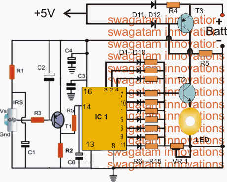
Referring to the schematic of the proposed LEd emergency lamp circuit with infrared remote dimming feature, the design basically comprises of three stages: the infrared toggled 4017 sequencer, the LED dimmer using T2, and the automatic emergency switch using T3.
The IR sensor is a standard TSOP series IC configured with a BJT buffer T1 which amplifies the output from IRS sensor each time its toggled with an external IR remote transmitter, which could be simply your TV remote control handset .
The above switching response is appropriately applied at the clock input of the IC 4017 which is a Johnson divider counter chip and becomes responsible for generating a sequencing positive high shifts across its pin3 (start) to pin (11) and back to pin3 (repeat).
Each of the above 10 sequencing high outputs are terminated via 10 individual rectifier diodes and a series resistor. The resistors are calculated so as to generate a proportionately incrementing potential difference at the base of T2 with reference to the value of the resistor set by VR1 across the base and ground of T2.
Depending upon which output of the IC4017 may be high at any given instant, the connected LED brightness is determined according to this selected output (toggled via the IR stage and the remote handset).
At pin3 the illumination may be the highest while at pin11 it could set to produce the minimum brightness over the attached LED.
T3 is positioned to invert its collector voltage in response to the input at its base acquired from an external AC to DC 5V adapter unit.
As soon as this supply is removed or fails, T3 switches ON via R5 allowing the required battery voltage to reach the collector of T2, which in turn passes it on to the LED connected across its emitter/ground terminals with the required amount of glow as determined by the specific output of the IC 4017 at that instant selected to be high by the user using the IR remote control facility.
Parts list for the above IR controlled LED emergency lamp with dimmer circuit
R1, R3 = 100 ohms,
R2 = 100K,
R4 = 4K7,
R5 = 10K,
R6---R15 = 200 ohms to 2K (proportionately incremented)
VR1 = 10k preset
C2 = 47uF/25V
C1, C4= 22uF/25V,
C3 = 0.1, CERAMIC,
T1 = BC557
BT2 =TIP122
T3 = TIP127
ALL DIODES ARE = 1N4148,
LED = 1 watt high bright
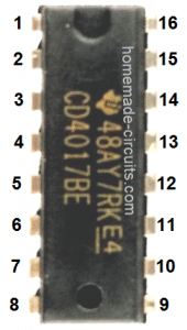
IC1 = 4017
Battery = 4V/4AH or bigger


Questions & Answers
Hi Swagatam,
I want to make a circuit to control a 12V DC motor thru IR remote. I have created a circuit to control lights using IR remote thru 555 timer and 4017, but I am not able to modify that circuit to change the direction of motor rotation, my requirement is to rotate the motor for certain duration in clockwise direction using one button on remote and in opposite direction using another button (or same button).
Can you please help?
Hi Ajay, you can use the same concept which is explained above, just replace the relay with a DPDT and wire the contacts in the following manner. However, you would be able to implement the controls using a single button, not through two separate buttons.
Thanks a lot. I did not think in this way earlier.
Really glad to see response on a comment that too in such a short duration. Keep up your innovative ideas, I am regular follower of your site.
You are most welcome!
hi
i m akmal lari & i want to make inductive type proximity sensor….can any one help …my mail id :lari.akmal@gmail.com
Swagatam,
I just realized an error in my thinking. The LED is running on 3.2v not 5v or 12v in my case, therefore the amperage is much higher than I figured. So, I understand why you are using higher capacity transistors. so, a tip 31 is good for three amps and a tip122 is good for 5amps and a tip 142 is good for 10amps. A tip 33 is also good for 10 amps. Why would you use a tip 142 instead of a tip 33? As you can tell, I'm a novice and I am learning. I hope you are not bothered by my questions. Thanks!
12V will not cause any harm since it is appropriately dropped by the transistor base resistive network to the LED level.
TIP122 is used because it is a Darlington BJT and offers a relatively large current handling capacity
TIP33 is not a Darlington so it won't work effectively.
Swagatam, I'm having a little trouble understanding why you are using tip 122 for the 1-watt led. It seams that the 1-watt LED is only drawing 200ma at 5v.?? Also I am using a 12v supply, so I guess I should use a 5.1v zener to reduce the voltage to the TSOP1728 as it only wants max 5v. What is the 10k trim pot doing for the circuit? In my circuit I'm running 7 watts at 12v, so I was thinking I could use a bc327 transistor for t2 to cover the 600ma current draw. I could step up to a darlington bc517 or even a tip 31. What do you think?
Norman, you can use any other suitable transistor but it must be a a darlington type. The TIP122 is a comparatively higher rated and therefore a heatsink can be avoided for this transistor, for a smaller rated BJT a heatsink might become compulsory.
yes you can use a 5V zener or a 78L05 IC.
the 10K preset forms a potential divider resistor with the 4017 output sequencing resistors and helps to generate the required potential alterations at the TIP122 base which is in turn causes the LED to get gradually brighter or dimmer.
the 10K preset should be adjusted such that at the highest brightness level it produces around 4.2V at the base of the BJT in conjunction with the particular 4017 pinout resistor, …..and produces around 3V in conjunction with the pinout resistor which is supposed to produce the lowest brightness on the LED.
you can use any combination for acquiring a Darlington pair, just make sure the main BJT is rated to handle at least 1 amp.
Thanks for the quick reply! Again, let me say, I love your Blog.
the pleasure is all mine!!
Hi Swagatam,
I would like to build a circuit to control the brightness of above cabinet and under cabinet LEDs. I was thinking I would have an IR remote transmitter and an IR receiver. The receiver would be connected to a CD4017 and each time the transmitter was pushed, the CD4017 would advance to a different pin. Each pin would have a different size resistor to change the current to the LEDs very similar to your "IR Controlled Emergency Lamp". Would you please change your "IR Controlled Emergency Lamp" circuit to allow my requirement. I am using 12vdc strip LEDs that require about 7-watts. I am using a standard 110v to 12v, 10W power supply. I could use an IR transmitter/ receiver pair purchased or I could build the transmitter and receiver from components. I would prefer to build the TX/RX from components, just for fun. Thanks for your great website! I really enjoy dabbeling in electronics. I just finished building several PIR actuated night lights for under the bed so when you have to get up in the night, a soft light automatically comes on under the edge of the bed to light your way. The light has an adjustable delay. My wife really likes them.
Thank you very much Norman,
you can use the same circuit that's explained above, with some minor modifications.
just eliminate the top T3 stage and all the parts associated with it.
connect the positive supply with the collector of the TIP122 along with the pin#16 line of the IC
you can consider about replacing the TIP122 with a TIP142 for better power delivery.
Thank u very much.
The circuit worked with me well i applied it to 12v dc led back up system but the problem is the circuit disturbed by outer frequencies for example when i turn on a CFL light the circuit start on and off several time before it stabilized again .so how i could make the sensitivity of the circuit less.
regards
Unfortunately there isn't an easy remedy for this…try enclosing the circuit inside a metallic box with a small hole for the tsop, and ground the box with the negative of the circuit, see if that helps
hai sir i want ir based tx and rx circuit between 3 feet distance obstetrical sensing circuit
please sir urgent reply me sir
Hi, do you want to make an obstacle sensor……you can try the following design:
https://www.homemade-circuits.com/2013/10/accurate-infrared-motion-detector-or.html
Sir I want to ask about the sequencer in CD 4017
Can we reverse this sequence..by using circuit from rc car.(2channel)
OK sir..thanks
sorry no, reversing a 4017 sequence is not possible by any means as far as I know…
nice circuit sir
thanks!