In this article I have explained how to make a simple fish aquarium oxygen generator circuit using the concept of electrolysis of water.
Generating Pure Oxygen
The production of oxygen through electrolysis can be expected to supply a pure and a bigger quantity of oxygen compared to the usual pumped air concept which injects only only a portion of oxygen in the aquarium, therefore using electrolysis procedure looks a more efficient than the pumped air option
In one of my earlier artilces I have explained how to generate oxygen and hydrogen gas through electrolysis in large volumes, here we employ the same principle for the generation of pure oxygen using mains rectified AC.
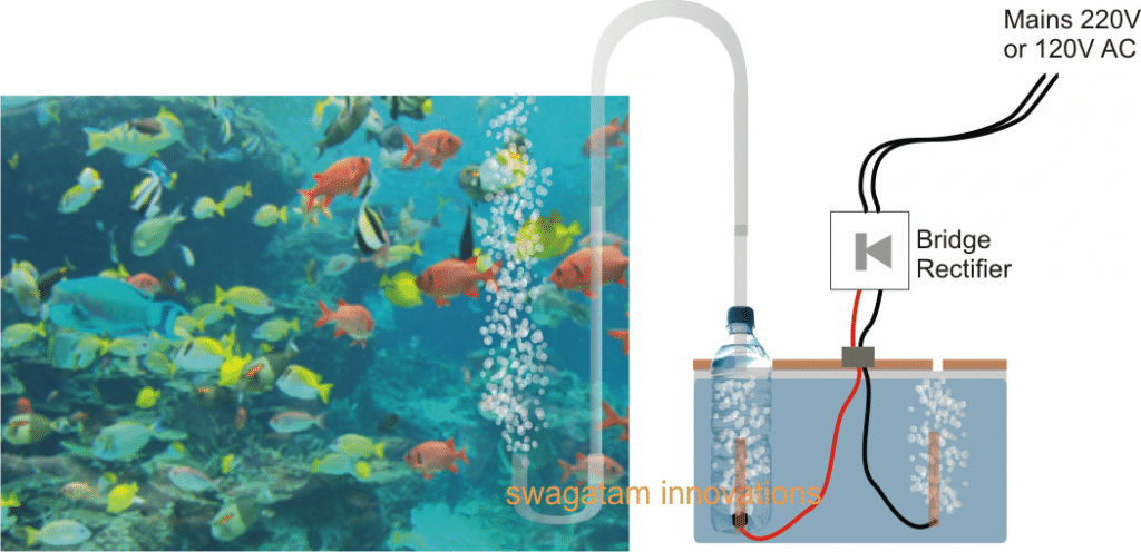
The complete operational set up can be witnessed in the above shown figure.
The right side section of the diagram shows a small tank filled with clean tap water, having a lid which is appropriately fabricated to hold a plastic bottle such that its neck can protrudes out, and having a small opening some distance away for allowing the unused hydrogen gas to escape.
Two wires can be seen entering the water container with one of the wires pushed inside the bottle from its bottom end and appropriately sealed with epoxy glue and the other wire loosely held just below the lid opening.
The wire entering the bottle end is tied up with an electrode which could be ideally of graphite (salvaged from an old dead AAA cells) in order to prevent degradation due to oxidization, overtime
The wires can be seen attached with the output of a bridge rectifier, which is supplied with an input from the mains AC 220V or a 120V.
When mains is switched ON, the power enters the bridge rectifier and gets converted into a pulsating DC, this DC is introduced inside the water tank for initiating the required electrolysis.
The potential at positive end electrode of the wire generates O, or pure oxygen, while the potential at the negative wire electrode breaks H+H atoms from water generating hydrogen which escapes through the lid opening into the atmosphere.
The oxygen gas is forced to bubble inside the water enclosed inside the bottle and it emanates through the tube into the aquarium where it bubbles back from bottom to the surface enriching the water with pure oxygen and making sure that the marine life inside the aquarium gets the best of the experience in terms of breathing and oxygen absorption.
Please note that in the discussed concept the water alone is forced to break into its constituent parts, absolutely NO external catalyst in the form acid or salt should be added in the electrolysis tank, which might otherwise cause the generation of poisonous gasses instead of oxygen.
Making the Bottle Oxygen Collector
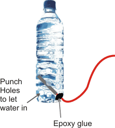
The bottle which acts as the intermediate oxygen collector can be easily built using any ordinary empty cold drink bottle or a mineral water bottle.
As demonstrated in the figure below, the wire end with the electrode is inserted from the bottom corner of the bottle and sealed with epoxy glue or putty.
Next, many small holes are punched near the bottom end of the bottle so that water is able to enter and fill the bottle and enable the process of electrolysis inside it.
Further on, a plastic flexible tube is inserted through the lid or the cork of the bottle and glued with epoxy, the other end of the tube is immersed in the aquarium jar for allowing the oxygen to pass into it for initiating the required fish aquarium oxygen generation.
After this the bottle is pushed in the tank so that water fills in and hlds the bottle erect in the tank. The wires are then appropriately attached with the bridge rectifier source enclosed inside a plastic box, with a mains cord terminating out from the input of the bridge.
That's it! Once the above procedures are finished, it's just about plugging and switching ON the mains, and watching the the oxygen bubbling out inside the fish aquarium, making the lives of the fishes merrier.
Warning: The explained electrolysis set up for the fish aquarium generator circuit is very dangerous due to the involvement of AC mains in the electrolysis tank. Extreme caution and safety must be exercised while building and testing the proposed units.

Questions & Answers
It is an interesting idea. But we need to see how much energy efficiency is, that is, how many grams of oxygen are absorbed by the aquarium water for every kilowatt of electricity consumption, oxygen absorption efficiency is very important for me, who is a professional breeder of aquarium fish.
Dear Sir Swagatam
Hello. I have sent you form 3 different IDs and all are back. Is your Email ID OK?
Truly yours
Hello Najieh, my email is working perfectly, I am able to receive all the other emails in my inbox without issues. I think you can upload the images in your google drive and send the link here, with shared option enabled.
Dear Sir Swagatam
Hello. I do not know what is the problem.
I’ve sent few emails to you before???
I will try tomorrow. I hope the problem would be solved
Thank you very much for your response
Truly yours
Thank you Najieh,
I understand that you have emailed me with pictures but maybe due to some unknown problems the message is not reaching me….hope it gets solved soon
Dear Swagatam
Hello. Thank you for your response, which, like the previous times, gave me confidence and taught me new things. one rod for hydrogen would be the best.
Just few minutes ago I sent a picture of the rods that I have prepared for the project from my new mail that has been created on google
Wish you health kind man
Truly yours
You are welcome Najieh, I wish you all the best!
I have received no pictures in my email ID so far.
Dear Swagatam
Hello. I removed the electrodes out the bottles and will send you a short video of the sum of the two gases that are being produced. Left side electrode is hydrogen.
Wish you all the best dear Sir
affectionately yours
…I saw the video and it looks great, but both the gasses the mixing together causing HHO to generate which is dangerous….so you must keep one electrode inside the bottle and the other outside as suggested in the diagram.
Dear Swagatam
Hello. It is me again, Najieh who does not know how to appreciate your favor and efforts that you deserve. Now I am sure how to make it to be safe. I will allocate 4 electrodes for oxygen inside a bottle with a few holes on it, and will fasten 1 electrode to outside of that bottle and everything would be OK.
Thank you again dear Swagatam.
Wish you healthy and all the best
Truly yours
That’s great Najieh, I am glad you could understand the procedures fully, and now you are ready to complete it perfectly…I appreciate your efforts.
Dear Swagatam
Hello. I’m ashamed that once again I need your help. Just one question; Since I have only the total of four “D” size cell graphite electrodes (which I thought they were called “A” size till now) and I plan to use all together for oxygen, would it be sufficient to use only one “A” size for hydrogen electrode or I should use 2 or…?
Thank you very much kind man
Truly yours
Not a problem Najieh!
You can use one or two electrodes, as per your convenience but just make sure they are close to each other, meaning the hydrogen rods should be at a touching distance to the outside of the bottle, or very near to the holes punched on the bottle.
Hello Najieh, OK that’s great, however removing the oxygen electrode out of the bottle will not allow you to send oxygen separately to the aquarium.
Dear Swagatam
Hell. More power to your elbow.
I made this project using two nos. of “A” size cell graphite rods along with bridge rectifier a few days ago, as well two half-liter plastic drinking water bottles. I wrapped the mains wires around graphite rods and tightened in the place and covered with epoxy potty. Then I made four holes in the lower part of each bottle, inserted the graphite rods into the bottles and fastened them to the body of the bottles using epoxy potty. I then inserted the bottles into a 4 liters glass jug and connected the wire to the mains supply. I am glad that it works well and must say that the volume of oxygen and hydrogen generating is very low and almost of a same value. My question is that is it possible for me to increase the number of graphite rods (to 4 or 5 nos.) only in the bottle that produces oxygen to have more oxygen? what is your idea about using long graphite rods of old transistor radios inside the aforementioned bottle instead of 4 or 5 nos of “A” size cell rod?
Thank you in advance for your reply
Truly yours
Thanks Najieh,
I am glad it is working for you.
You can increase the gas production by bringing the two electrodes close to each other but make sure both electrodes are not inside the bottle.
Radio antenna has a ferrite rod, not graphite, so that may not work correctly.
Dear Swagatam
Hello. Just now I cut two opposite sides of the bottles, fastened them together, and the distance between electrodes reduced the 4 cm. the result is producing much more hydrogen??!! bobbles of oxygen collects around it,s electrode but a lot of cloud-like particles boils upward the hydrogen rod. I should say that he percentage of O to H2 has been 1 to 3 since today.
I want you to please note this update in answering my one hour ago letter.
Truly yours
Yes hydrogen will be more than oxygen, but it cannot be 2 time more, there may be some impurities that may be causing cloud like appearance.
Dear Swagatam
Hello. Thank you very much for your reply. In response to your honorable letter, would you please take a look at the following issues
x – I think I can put a thin piece of plastic between two electrodes and tie them together with nylon thread to produce more oxygen. however, since I do not need the hydrogen for my aquarium fish do you know how to separate oxygen and direct it to fishes? If I want to put a plastic tube on the oxygen rod again and connect a plastic tube to it, the problem will not be solved. Please help me.
xx – I did not have your comment on using 4 electrodes stuck together instead of one electrode (for producing more oxygen) versus just one electrode for hydrogen.
Thank you very much for your kindness
Truly yours
Hello Najieh, the bubbles from both the electrodes should not mix with other, otherwise you cannot get oxygen separately. You can keep the oxygen electrode inside the bottle, and keep the hydrogen electrode just outside the bottle, that is nearest possible distance you can get.
Increasing the number of electrodes can also help to produce more gas.
Install both electrodes inside two separate bottles. Connect a pipe to the bottle containing hydrogen and direct the hydrogen outside the house through the window. Hydrogen has the ability to explode
Hi dear Sir Swagatam
We have seen and heard that some old oxygen operating baloons were used to carry people had been exploded. I have made your plan and am very satisfied with it; so the fishes of course. Since the produced hydrogen is released into the room, wouldn’t it be harmful? or I should attach a flexible thin hose to the hydrogen whole in order to send the produced hydrogen out of the room.
Thank you in advance
Truly
Mike
Thank you Mike, for updating the results. I am glad you could make the project successfully.
If you have proper ventilation in your house then I don’t think their would be any problems, since the H2 would escape from the ventilation quickly.
By the way it is HHO that is more dangerous compared to H2 alone.
That said if you want to use a pipe to direct the H2 gas out of the room then that can be the best option.
Hello dear Swagatam and thank you very much for so soon and comprehensive reply to my letter.
Wish you all the best
Best regards
Mike
Thank you Mike, I am glad to help!
Dear Sir Swagatam
Thank you for your helping and kindness. Please excuse me for bothering you.
Wish you health and joy
Mehrdad
No problem Mehrdad, I am always happy to help!
Dear sir Swagatam
Hello. you did a very great favor for your comprehensive ressponse. Thank you very much Sir. I should clarify few tips regarding my last letter:
About No 2: I am sorry. I meant as you have described but I had not written it clearly.
About No 4: I sent a picture to your Email in which I have described what did I mean.
About No 5: Are you informed that they are using pure oxygen at hospitals or they mix the pure oxygen with some percent of the weather that all of us are breathing every moment.
Thanking is the least I can do for your goodness and kindness.
Wish you all the best
Best regards
Mehrdad
You are welcome Mehrdad, I checked the picture as sent by you, yes it can be used for the present purpose!
It is not confirmed by me whether the oxygen in hospitals are 100% pure or not, but I believe it is 100% pure so that it produces maximum benefit to the sick patients!
It is not so, sir. The oxygen capsules used in hospitals only separate about ninety percent of nitrogen from atmospheric air by a process called oscillating absorption under pressure, while pure oxygen can cause poisoning.
Dear sir Swagatam
Hello. Thank you so much for the proposed link. I plan to set it up soon, hence I would be very glad if you kindly tell me what do you think about the following tips and that if I am right:
1.The bottom of the glass or plastic tube is open enough in order to let the water enter it as it consumes?
2. I am to solder the mains wires to the metal cover of the old dead AAA cell graphite electrodes and cover that metal part with twin glue.
3. Do AA or A size cell graphite electrodes produce more oxygen.?
4. Doesn’t it matter if I use a “medical infusion (serum) set with roller clamp” instead of the valve of the glass tube shown in the picture, and seal the top of the tube with glue?
5. Our produced oxygen would be %100 pure. Do they use the same percent of oxygen at hospitals too?
Thank you in advance for your favor
Best regards
Mehrdad
Dear Mehrdad,
1) Yes that is true.
2) The mains AC wires will go to the bridge rectifier, and the output DC from the bridge rectifier will go to the graphite rods
3) The diameter and length of the graphite rod will be directly proportional to the oxygen production.
4) Sorry, I do not know about medical infusion set, so can’t suggest about it.
5) I am not sure about the purity level of the oxygen, since tap water can contain many impurities which can also mix with the gas, this will need to be verified in a professional lab.
Dear Sir Swagatam
Hello. Thank you very much for this good project. you have clearly explained all tips. Just a question: Am I allowed to use the produced oxygen for an ill who has left the hospital but he needs to inhale oxygen for a few days at home and if the volume of the oxygen is probably low, what do you say about using 54xx diodes instead of 4007?
Best regards
Mehrdad
سلام مهرداد، مانعی برای استفاده از اکسیژن حاصل از الکترولیز برای بیمار وجود نداره. فقط ماسک اکسیژن بیمار را کاملا کیپ نکن تا کمی هوای معمولی هم با اکسیژن مخلوط بشه
Dear Mehrdad, I won’t recommend using this oxygen production setup for sick human beings. I have a better oxygen generator idea presented in the following article which you can refer to:
How to Generate Pure Oxygen and Hydrogen at Home
I’ve thought of doing this when I had fish.. I even bought an ozone generator which seemed to invigorate my fish.. But it would seem that you could capture the hydrogen too and boil water with it. air pumps are very noisy although they are getting better. I have rooted plants with bubbled air. I imagine that bubbled Oxygen might be more effective. any thoughts.
Yes bubbled oxygen is more effective due to higher absorption rate by the water….the above article employs bubbled oxygen.
I wonder how much electricity power is being consumed by this project?
Will the Acurium water shock by this morning operation? If I use DC adapter then that mechanism will work? How times I have to refills small tank water?
Aquarium water has no contact with the electrolysis process or the AC mains so the question of shock does not arise…
low DC will not produce much gas
If we inhale the hydrogen gas coming out from the tank than it will be dangerous to our health
Yes it it gets ignighted you might die.. the guy who discovered hydrogen almost died. but the hydrogen should not hurt the fish
the hydrogen will not enter the fish aquarium, it is supposed to escape from the vent provided in the electrolysis chamber…
hydrogen is lighter than air, so it will never stay inside the room….
Sir, your circuit diagram is very economical and nice. AC is converted in to Dc by using Bridge Rectifier but what is the specification of Bridge Rectifier and how much it creates DC Volts ? Electrolysis means separating Oxygen & Hydrogen from each other and pure Oxygen to supply to Fish Tank. Sir, I think and it I am not wrong this technique is used De-Toxing Cum Foot-Spa machine where AC is converted in 24 Volts DC by a Transformer used in the machine. I would like you valuable opinion in this regards. Satish, praneelpune@gmail.com
Thanks Satish,
The bridge can be made using 1N4007 diodes as explained here:
https://www.homemade-circuits.com/2012/09/how-to-generate-pure-oxygen-and.html
Foot spa machine is a scam and is only to fool the consumer….the electrolysis is used for artificially dispersing chemicals in water which give an illusion of foot releasing dirt and getting detoxified.
How do I feed the fish since the aquarum is closed completely or would the fish only survive with oxygen alone here.
Hydrogen MUST go outside so it doesn't explode inside.
yes the small aperture on the lid is specifically for allowing the H2 to escape.