The circuit idea I have I have explained in this article can be used for controlling the intensity of many LEDs through a ceiling fan dimmer switch unit.
This circuit was requested by Mr. Joseph who wanted a simple method through which an ordinary home dimmer switch could be integrated with a chain of LEDs for controlling its brightness from zero to max. Let's learn more.
Technical Specifications
Hi there!
I noticed your blog online and I could really use your help. Are you too busy to work on a 19 LED circuit (dimmable with basic TRIAC dimmer, 120V mains, and transformerless)? I know the LED's I want to use and have a good idea about the other components, but I'm not an engineer like you.
I would be able to pay you; not much, but some of my own money. This project is my first lighting project and I'm doing it all on my savings so that I don't have to work with crappy investors who want to take it all!!
I hope to hear from you soon! Thanks!
Hi,
I don't think you would need a triac dimmer for this application, you can do it just by using a few capacitors and resistors and a pot. I'll show you how to do it in my blog...
Regards
Swagatam.
Thanks for the reply! I have felt alone in this venture and ANY help is very, very much appreciated.
Well, here's the deal here in the U.S.. Everyone wants an LED fixture, but they don't want to replace their old style wall dimmers.
They do want to dim their fixtures from their old mains dimmer with a wide range (10%-100%). The LEDs I want to use are a chain of 350mA – 3V.
I'm trying to achieve >300 lumens from one fixture (quantity of LED's could vary). So I started a bit of research on the following component…
There's a video on that page explaining exactly what I'm in search of. It's an affordable component and can be used with a transformerless circuit.
I also got beat to the market with a product by Tech Lighting (which is actually not made well and very, very expensive for the consumer)…
The big things in LED market right now… dimmable (nearly full range), remote phosphor coated diffuser (cooler), dimmable with old style dimmers (not just CFL/LED dimmers), very small footprint (low profile), chainable fixtures, etc. etc.. Basically everyone wants what old technology "can do" but they want the energy savings and low temperatures of LED lighting.
Thanks already for any help! I'm lost!
The Design:
The above request can be implemented in two possible ways, let's refer the respective diagrams and understand how we can control an LED tube light circuit using a dimmer switch.
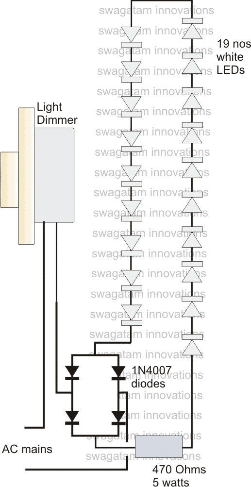
In the above figure we can see a chain of LEDs connected in series and powered in the usual manner via a bridge rectifier and a limiting resistor.
As suggested in the request the supply has been derived from a dimmer switch by connecting the LED circuit in series with the dimmer switch.
As we all know a dimmer switch is able to reduce power to the output load by chopping of sections of the AC mains such that the overall value of the AC gets reduced and thus the connected load also receives a cut down power.
However the triac would be able to handle current that's within its rated specs.
Therefore we connect a 470 Ohms resistor in series with the LEDs which makes sure that the dimmer remains safe even at full LED illuminations.
This resistor might get considerably hot at full brightness and vice versa, therefore it's rated at 5 watts, yet it will get hot.
If the heating up of the resistor looks undesirable, the above circuit may be modified in the following manner.
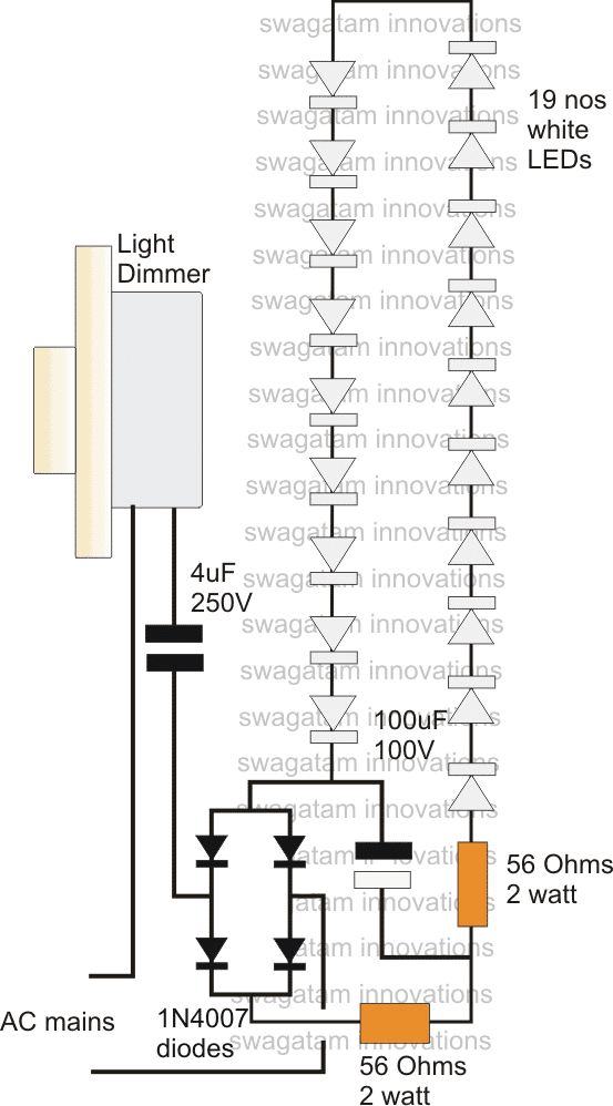
As can be witnessed in the above diagram, a high voltage, high value capacitor has been introduced at the input of the LED chain, which means now the voltage from the dimmer switch has to pass through this capacitor before reaching the LEDs.
The capacitor effectively restricts high currents from entering the circuit keeping the dimmer as well as the LEDs completely safe, and also eliminates the need of using high wattage "hot" resistors.
However, during switch ON the capacitor (as per its standard characteristics) will act like a "short" for a fraction of a second. This might inflict high initial surge voltage impact to the connected vulnerable LEDs. Though it will not do any harm to the dimmer, can instantly damage the LED chain.
For restricting this initial surge, a resistor/capacitor "sand box" is inserted at the positive line of the LED.
The two 56 Ohm resistors and the 10uF/100V capacitor effectively absorbs the initial surge and keeps the LEDs safe and illuminating.
The number of LEDs is not critical any number can be used provided the total forward voltage comes within the supply voltage range.
WARNING: THE IDEA IS BASED ON MY ASSUMPTIONS ONLY, AND HAS NEVER BEEN TESTED PRACTICALLY. APPROPRIATE CAUTION MUST BE OBSERVED BY THE CONSTRUCTOR.
USE A SERIES 100 WATT BULB WHILE TESTING THE PROTOTYPE. THE BULB SHOULD REMAIN COMPLETELY SHUT OFF WHILE OPERATING THE DIMMER FROM ZERO TO MAX. IF THE BULB ILLUMINATES WOULD MEAN SOMETHING'S WRONG WITH THE CIRCUIT.


Questions & Answers
Hello sir the resistor are heating as well I reduce upto 33 ohm
Hello basit try a 10 ohm/3 watt resistor
Can I increase the no.s of led upto 25
Hello Basit, reduce it to 10 ohms and check.
Hello sir I have just make this circuit so the circuit work fine bt the two resistor 56 Ohms 2 watt it get too hot every time wat will be the reason for that
yes you can do it
Ok thanks
Ok
Ok
So can use 4pcs of 1uf 400v in parallel for that and 1watt led can be used for the circuit
ye will do, but make sure the dimmer is in minimum position when power is switched ON, then slowly increase the dimmer for full illumination,
Hello sir can I use 1watt led for this circuit and can I use 1uf 400v ppc instead of 4uf 250v……..
hello basit, 1uF will produce only 70mA current,, not sufficient for driving 1 watt LEDs….therefore the shown 4uF is the correct value
Boss by varying the Regulator doe thee brightness reduce?
Is this ckt successful yet?
Please reply!!
Ho Rohith,
yes you can connect it with direct mains AC, refer to this article for more info:
https://www.homemade-circuits.com/2012/04/how-to-make-led-bulb-circuit.html
Hi sir, iam interested in making second one but what if i do not need to dim the LEDs?and there by using the second one connecting to 230v ac without a dimmer? as a daily usage lighting system? can it b possible???
The above circuits have not been tested…..however the second circuit looks more feasible and safe.
It will control the led intensity from zero to max.