• Skip to main content
  • Skip to primary sidebar

Homemade Circuit Projects

Get free circuit help 24/7

New Projects | Privacy Policy | About us | Contact | Disclaimer | Copyright | Videos | Circuits for Beginners | Basic Circuits | Hobby Projects | Transistor Circuits | LED Drivers 

You are here: Home / 555 IC Circuits / Beacon Level Indicator Circuit for Combine Harvester Grain Tanks

Beacon Level Indicator Circuit for Combine Harvester Grain Tanks

Last Updated on July 6, 2019 by Swagatam 2 Comments

caution electricity can be dangerous

The post explains a beacon indicator circuit for combine harvester grain tanks. The idea was requested by Mr. John Bosch.
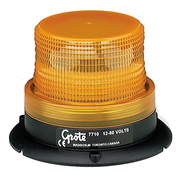
Circuit Objectives and Requirements

  1. I would like to retrofit the rotating beacon grain tank level indicator system shown below,  to my older combine harvester.
  2. The particular part of the system I want to build is this:
  3. Turns on automatically when the grain tank level reaches three-quarter.
  4. Beacon lights begin an alternating pattern once the three-quarters full sensor is triggered; beacon lights remain on for 10 seconds then turn off for 10 second continually repeating until the grain tank full sensor is triggered.
  5. Once the grain tank full sensor is triggered the beacon lights remain on constantly.
  6. Would you be able to design a circuit to perform this function? I already have the bin level sensor, and it is a normally open type of contact.
  7. The specs on the sensor are: 48V, .5amp, 10 watt, 300mA, so even though I’m planning on using LED beacon lights, I suspect the output of any circuit would have to trigger a relay to a power circuit for the beacons. I would also like to be able to switch the system off from the control station of the combine.
  8. Thanks in advance for any and all input!

The Design

The proposed beacon level indicator for grain tanks can be very simply implemented using an IC 555 circuit in its astable mode, as shown below:
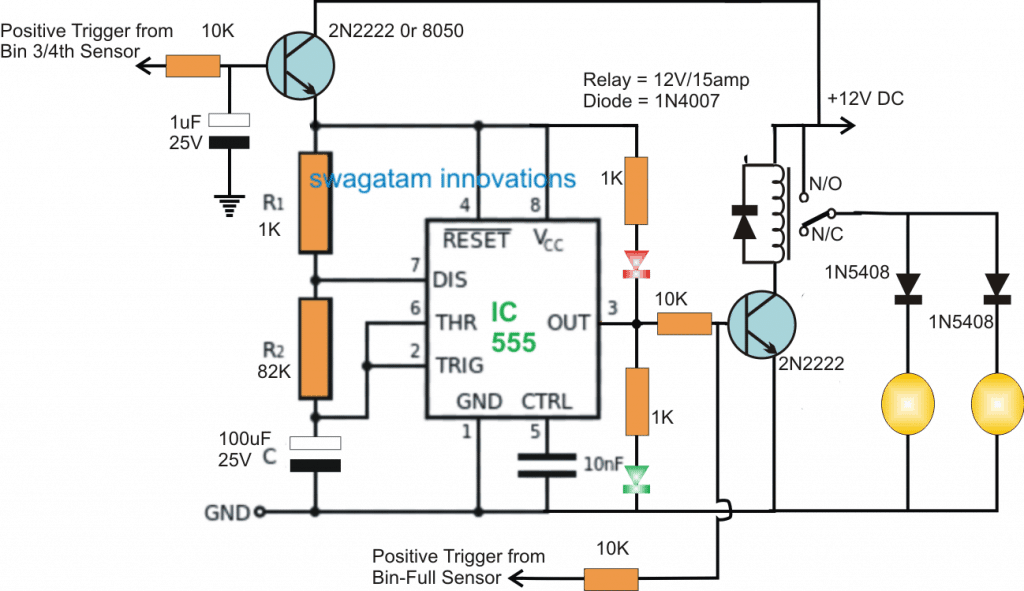
 

Beacon Level Indicator Circuit for Combine Harvester Grain Tanks

The IC 555 is configured in its standard astable mode (flashing mode), where R1,R2, and C values determine the flashing rate of the IC at its pin#3.

These values are calculated to produce a reasonably precise 5 second ON/OFF switching on pin#3 of the IC.

How it Works

Pin#3 can be seen connected with a relay driver stage whose contacts are configured with the indicator beacon LED lamps.

When the +12V supply from the relay side is switched ON, the circuit is put on a standby position and ready to respond to the signals from the bin sensors.

As soon as the first signal is received from the "3/4 tank full sensor" the astable gets powered through the relevant 2N2222 transistor on the top left, and the circuit immediately begins oscillating at the set rate.

The relay follows the ON/OFF triggers from pin#3 of the IC and initiates the required 5 second ON/OFF activation for the attached rotating beacon lights, indicating that the 3/4 tank full level is reached.

The above ON/OFF is sustained for a period of time until the grain tank reaches its full level, when the subsequent trigger from the "full level sensor" causes a permanent activation of the driver transistor and the relay.

The relay now becomes locked and enables both the beacon indicator lamps to be ON and rotating, indicating the "tank full" situation to the user.

You'll also like:

  • 1.  LED Strobe Light Circuit with Chasing, Flashing Effects
  • 2.  Intruder Position Indicator Security Circuit
  • 3.  Flashing LED Battery Low Indicator Circuit
  • 4.  Solar Insect Killer Circuit for Protecting Crops in Farms
  • 5.  LED Star Circuit
  • 6.  Rotating LED Chakra Circuit for God Idols

About Swagatam

I am an electronic engineer (dipIETE ), hobbyist, inventor, schematic/PCB designer, manufacturer. I am also the founder of the website: https://www.homemade-circuits.com/, where I love sharing my innovative circuit ideas and tutorials.
If you have any circuit related query, you may interact through comments, I'll be most happy to help!

Have Questions? Please Comment below to Solve your Queries! Comments must be Related to the above Topic!!

Subscribe
Notify of
2 Comments
Newest
Oldest
Inline Feedbacks
View all comments

Primary Sidebar

Calculators

  • 3-Phase Power (15)
  • 324 IC Circuits (19)
  • 4017 IC Circuits (52)
  • 4060 IC Circuits (25)
  • 555 IC Circuits (98)
  • 741 IC Circuits (19)
  • Arduino Engineering Projects (83)
  • Audio and Amplifier Projects (114)
  • Battery Chargers (82)
  • Car and Motorcycle (94)
  • Datasheets (46)
  • Decorative Lighting (Diwali, Christmas) (33)
  • Electronic Components (100)
  • Electronic Devices and Circuit Theory (36)
  • Electronics Tutorial (116)
  • Fish Aquarium (5)
  • Free Energy (34)
  • Fun Projects (13)
  • GSM Projects (9)
  • Health Related (20)
  • Heater Controllers (29)
  • Home Electrical Circuits (102)
  • How to Articles (20)
  • Incubator Related (6)
  • Industrial Electronics (28)
  • Infrared (IR) (40)
  • Inverter Circuits (98)
  • Laser Projects (12)
  • LED and Light Effect (93)
  • LM317/LM338 (21)
  • LM3915 IC (25)
  • Meters and Testers (65)
  • Mini Projects (148)
  • Motor Controller (67)
  • MPPT (7)
  • Oscillator Circuits (26)
  • PIR (Passive Infrared) (8)
  • Power Electronics (34)
  • Power Supply Circuits (77)
  • Radio Circuits (10)
  • Remote Control (48)
  • Security and Alarm (61)
  • Sensors and Detectors (120)
  • SG3525 IC (5)
  • Simple Circuits (75)
  • SMPS (29)
  • Solar Controllers (60)
  • Timer and Delay Relay (53)
  • TL494 IC (5)
  • Transformerless Power Supply (8)
  • Transmitter Circuits (40)
  • Ultrasonic Projects (16)
  • Water Level Controller (45)

Calculators

  • AWG to Millimeter Converter
  • Battery Back up Time Calculator
  • Capacitance Reactance Calculator
  • IC 555 Astable Calculator
  • IC 555 Monostable Calculator
  • Inductance Calculator
  • LC Resonance Calculator
  • LM317, LM338, LM396 Calculator
  • Ohm’s Law Calculator
  • Phase Angle Phase Shift Calculator
  • Power Factor (PF) Calculator
  • Reactance Calculator
  • Small Signal Transistor(BJT) and Diode Quick Datasheet
  • Transistor Astable Calculator
  • Transistor base Resistor Calculator
  • Voltage Divider Calculator
  • Wire Current Calculator
  • Zener Diode Calculator

© 2023 · Swagatam Innovations

wpDiscuz