• Skip to main content
  • Skip to primary sidebar

Homemade Circuit Projects

Get free circuit help 24/7

New Projects | Privacy Policy | About Us | Contact | Disclaimer | Copyright | Videos 

You are here: Home / Mini Projects / Blinking LED Bow Tie Circuit

Blinking LED Bow Tie Circuit

Last Updated on November 4, 2023 by Swagatam Leave a Comment

In this post we will discuss how to build an LED bow tie circuit which will activate and blink a few LED lights stuck on your bow tie in response to your voice sound. It means, the LED lights on your bow tie will flash and blink, whenever you speak, creating a very eye catching effect on your bow tie.
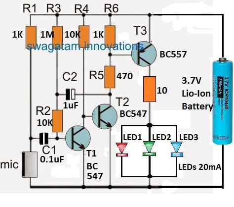
caution electricity can be dangerous

Circuit Diagram

blinking bow tie LED circuit

Parts List

  • Resistors 1/4 watt CFR unless specified
  • 1K = 2
  • 10k = 2
  • 1M = 1
  • 470 Ohms = 1
  • 10 Ohms = 1
  • Capacitors
  • 0.1uF Ceramic = 1
  • 1uF/25V Electrolytic = 1
  • Transistor BC547 = 2
  • Transistor BC557 = 1
  • LEDs = Quantity as Required, 20 mA, 5mm type
  • Electret MIC = 1
  • Battery 3.7 V = 1

Circuit Description

The following points can be used to understand how the bow tie LED light circuit operates, with reference to the circuit schematic above.

As a whole, resistors R1, R2, and R3 and transistor T1 work like a basic electret MIC preamplifier circuit.

This stage's primary job is to increase the MIC's tiny electrical pulses into comparatively bigger voltage pulses.

The resistors R4, R5, and R6, in conjunction with transistors T2 and T3, are set up to function as a power amplifier.

This power amplifier's function is to greatly increase the voltage and current output from the preamplified pulses at T1's collector.

At the collector of transistor T3, the set of 3 LEDs is eventually driven and illuminated by this increased voltage and current.

To provide the LEDs a delay OFF function, resistor R3 and capacitor C2 are utilized. This makes sure that even when the sound vibrations on the MIC stop, the LEDs continue to glow for a few seconds.

The delay OFF timing of the LED switch OFF period may be adjusted by increasing or decreasing the C2 value.

Formula for the delay off timing is:

t = −RC⋅ln(1−VS​/VC​​)

where:

  • t is the delay time in seconds
  • R is the resistance in ohms
  • C is the capacitance in farads
  • VC is the voltage across the capacitor at which the timer turns off
  • VS is the supply voltage

In order to enhance the battery efficiency you can completely eliminate this delay off feature by removing the C2 capacitor from the circuit.

The R1 resistor's value may be altered to change the circuit's sensitivity. Sensitivity is reduced as the value is increased, and vice versa.

Battery Selection

The battery can be any Li-ion AAA 3.7V type, or if you want it to be even more compact, you can use two Li-ion 3V coin cells, attached in series.

Since the LEDs would activate only in response to voice sounds, most of the time the circuit will be inactivate allowing a long life for the battery.

When the battery gets discharged you can charge them using a cell phone charger, but make sure to use a 6V incandescent flashlight lamp in series. If you don't have the lamp, you can use a 50 ohm 1 watt resistor in series.

LED Selection

The LEDs can be of different colors, all high bright 3.3 V, 20 mA type. You can put around 3 to 6 LEDs in parallel as shown in the diagram.

Get New Circuit Diagrams in your Email

You'll also like:

  • 1.  Up/Down LED Indicator using LM3915
  • 2.  4 Simple Proximity Sensor Circuits – Using IC LM358, IC LM567, IC 555
  • 3.  Simple FET Circuits and Projects
  • 4.  How to make simple a LI-FI (Light Fidelity) Circuit
  • 5.  How to Generate Electricity from Sea Water – 2 Simple Methods
  • 6.  Real Machine Gun Sound Effect Generator Circuit

About Swagatam

Swagatam is an electronic engineer, hobbyist, inventor, schematic/PCB designer, manufacturer. He is also the founder and the author of the website: https://www.homemade-circuits.com/, where he loves sharing his innovative circuit ideas and tutorials.
If you have any circuit related queries, you may interact through comments, and get guaranteed replies from the author.

Reader Interactions

Post your comments here and get guaranteed replies. Comments must be related to the above article. Cancel reply

Your email address will not be published. Required fields are marked *


Primary Sidebar

Categories

  • 3-Phase Power (15)
  • 324 IC Circuits (19)
  • 4017 IC Circuits (52)
  • 4060 IC Circuits (27)
  • 555 IC Circuits (99)
  • 741 IC Circuits (20)
  • Arduino Engineering Projects (83)
  • Audio and Amplifier Projects (126)
  • Battery Chargers (83)
  • Car and Motorcycle (96)
  • Datasheets (78)
  • Decorative Lighting (Diwali, Christmas) (33)
  • Electronic Components (101)
  • Electronic Devices and Circuit Theory (36)
  • Electronics Tutorial (121)
  • Fish Aquarium (5)
  • Free Energy (34)
  • Fun Projects (15)
  • GSM Projects (9)
  • Health Related (22)
  • Heater Controllers (31)
  • Home Electrical Circuits (107)
  • How to Articles (20)
  • Incubator Related (6)
  • Industrial Electronics (28)
  • Infrared (IR) (40)
  • Inverter Circuits (99)
  • Laser Projects (13)
  • LED and Light Effect (101)
  • LM317/LM338 (22)
  • LM3915 IC (25)
  • Meters and Testers (69)
  • Mini Projects (152)
  • Motor Controller (69)
  • MPPT (7)
  • Oscillator Circuits (25)
  • PIR (Passive Infrared) (9)
  • Power Electronics (35)
  • Power Supply Circuits (86)
  • Radio Circuits (10)
  • Remote Control (50)
  • Security and Alarm (66)
  • Sensors and Detectors (132)
  • SG3525 IC (5)
  • Simple Circuits (75)
  • SMPS (29)
  • Solar Controllers (63)
  • Timer and Delay Relay (55)
  • TL494 IC (5)
  • Transformerless Power Supply (9)
  • Transmitter Circuits (42)
  • Ultrasonic Projects (17)
  • Water Level Controller (45)

Calculators

  • AWG to Millimeter Converter
  • Battery Back up Time Calculator
  • Capacitance Reactance Calculator
  • IC 555 Astable Calculator
  • IC 555 Monostable Calculator
  • Inductance Calculator
  • LC Resonance Calculator
  • LM317, LM338, LM396 Calculator
  • Ohm’s Law Calculator
  • Phase Angle Phase Shift Calculator
  • Power Factor (PF) Calculator
  • Reactance Calculator
  • Small Signal Transistor(BJT) and Diode Quick Datasheet
  • Transistor Astable Calculator
  • Transistor base Resistor Calculator
  • Voltage Divider Calculator
  • Wire Current Calculator
  • Zener Diode Calculator

© 2023 · Swagatam Innovations