In this post I have explained how a shunt regulator IC works typically in SMPS circuits. We take the example of the popular TL431 device and try to understand its use in electronic circuits through a few of its application notes.
Electrical Specifications
Technically the device TL431 is called a programmable shunt regulator, in simple terms it may be understood as an adjustable zener diode.
I have explained more about its specifications and application notes.
The TL431 is attributed with the following main features:
- Output voltage settable or programmable from 2.5V (minimum reference) up to 36 volts.
- Output Impedance low dynamic, around 0.2 Ohm.
- Sink current handling capacity up to maximum 100mA
- Unlike normal zeners, noise generation is negligible.
- Switching response lightning fast.
How the IC TL431 works?
The TL431 is a three pin transistor like (such as BC547) adjustable or programmable voltage regulator.
The output voltage can be dimensioned using just two resistors across the specified pin outs of the device.
The diagram below shows the internal block diagram of the device and also the pin out designations.
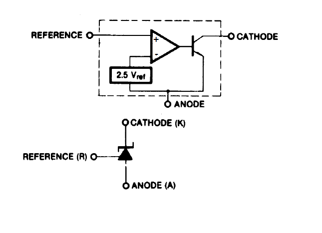
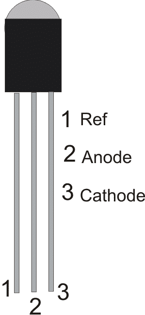
The following diagram indicates the pin outs of the actual device. Let's see how this device can be configured into practical circuits.
Audio/Video Representation
Circuit Examples using TL431
The circuit below shows how the above device TL431 can be used as a typical shunt regulator.
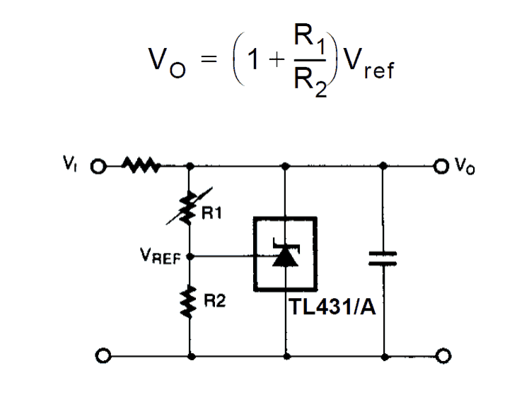
The above figure shows how with the help of just a couple of resistors the TL431 can be wired up as a shunt regulator for generating outputs between 2.5v to 36v. R1 is a variable resistor which is used for adjusting the output voltage.
The series resistor at the supply positive input can be calculated using Ohm's law:
R = Vi / I = Vi / 0.1
Here Vi is the supply input which must be below 35 V. The 0.1 or 100 mA is the maximum shunting current specification of the IC, and R is the resistor in Ohms.
Calculating Shunt Regulator Resistors
The following formula holds good for acquiring the values of the various components used for fixing the shunt voltage.
Vo = (1 + R1/R2)Vref
Here Vref is always equal to 2.5 V, which is internally set for the TL431 IC.
So the formula finally can be expressed as:
Vo = (1 + R1/R2) x 2.5
Practical Example
Let's try to understand the calculations through a practical example, as shown below:
In this example we will try to use the TL431 to regulate the output supply voltage to 12 V.
Let's assume we have all the parameters given, except R1.
- Given:
- Vo = 12V
- R2 = 1K
- R1 = ?
- Vref = 2.5
Vo = (1 + R1/R2) x 2.5
12 = (1 + R1/1000) x 2.5
12 = [(R1 + 1000) / 1000] x 2.5
12/2.5 = (R1 + 1000) / 1000
4.8 = (R1 + 1000) / 1000
4800 = R1 + 1000
R1 = 3800 = 3.8 K
Thus, by using a 3.8 K resistor for R1 we can regulate the output voltage of the TL431 to an exact 12 V level. Likewise, you can alter the values of R1 and R2 to get other regulated values at the output as required.
Modifying 78XX IC Output Voltage using TL431
In case a 78XX needs to be used in conjunction with the device, the following circuit can be used. In this example we can see how the output voltage of the a 7805 IC is modified to increase above its normal 5 V level. For example here the 7805 IC output could be increased to 9V by suitably adjusting the TL431 parameters.
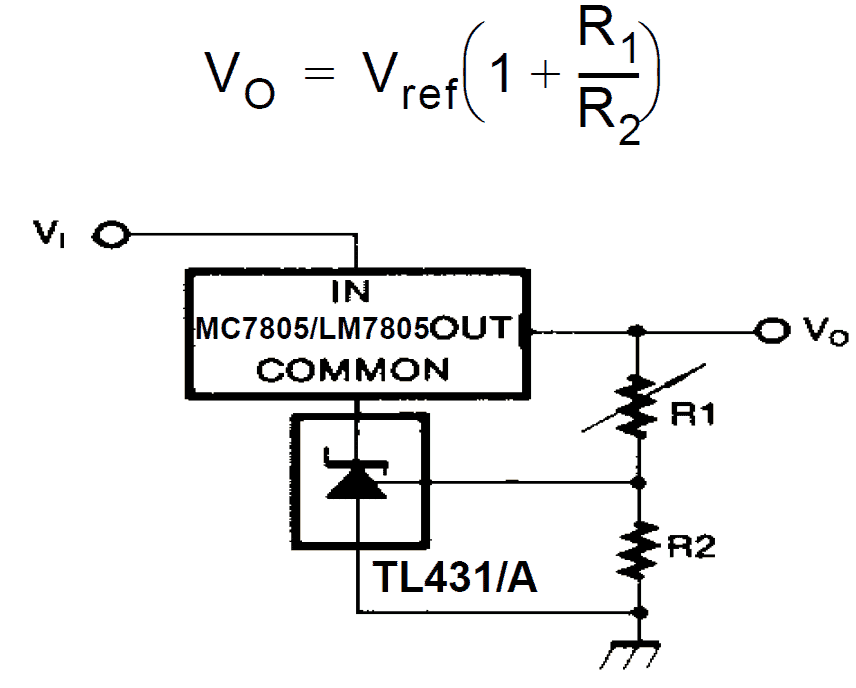
The ground of the TL431 cathode is connected with the ground pin of the 78XX. The output from the 78XX IC is connected with the potential divider network which determines the output voltage.
The parts can be identified through the formula shown in the diagram.
The above configurations are restricted to a max 100 mA current at the output.
Making a High Current Shunt Regulator using TL431
Normally, the TL431 adjustable zener diode cannot used with currents over 100 mA. However this device can be configured to shunt higher amount of currents by adding an external shunting transistor with the output of the TL431.
For working with higher current a transistor buffer may be used, as shown in the following circuit.
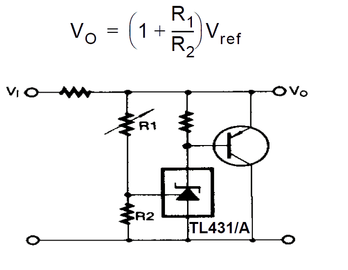
In the above diagram most of the parts placement is similar to the first shunt regulator design, except that here the cathode is provided with a resistor to positive and the point also becomes the base trigger of the connected buffer transistor.
The output current will depend on the magnitude of current the transistor is able to sink.
In the above diagram we can see two resistors whose values are not mentioned, one in series with the input supply line, another at the base of the PNP transistor.
The resistor at the input side limits the maximum tolerable current that can be sinked or shunted by the PNP transistor. This can be calculated in the same way as discussed previously for the first TL431 regulator diagram. This resistor protects the transistor from burning due to short circuit at the output.
The resistor at the base of the transistor is not critical and may arbitrarily selected anything between 1k and 4k7.
Making a Precision Shunt Regulator using TL431 for Windmill Applications
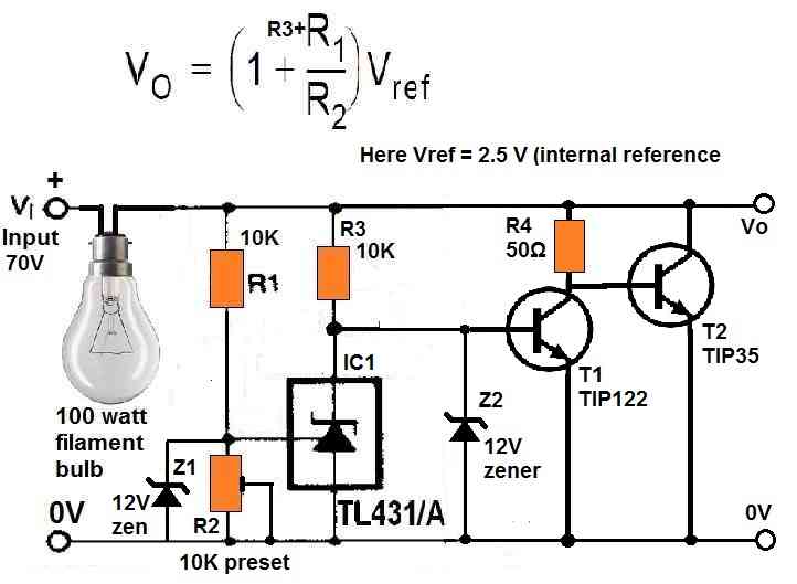
The following image shows how the TL431 device can be used for controlling windmill generators for charging upto 48 V batteries.
In this design, the TL431 IC is well protected with 12 V zener diodes to ensure the internal circuitry of the device is not subjected to extreme breakdown voltages.
The 1K preset is adjusted such that the TL431 just conducts at around 56 V which is optimal level for charging a 48 V battery.
As soon as the TL431 conducts, the T1 shuts off, causing T2 to turn ON.
When T2 turns ON, it shunts the supply voltage to ground thus regulating the supply voltage at the desired level.
Application Areas of the IC TL431
Although the above configurations can be used in any place where precision voltage setting and references may be required, it's extensively used in SMPS circuits nowadays for generating precise reference voltage for the connected opto coupler, which in turn prompts the input mosfet of the SMPS to regulate the output voltage precisely to the desired levels.
For more info please go to TL431 Datasheet


Questions & Answers
You are welcome!
Great article!
Thanks you. Was very helpful.
you are welcome
can also use 2N3819
Can also use 2N3819
where?
I copied it from the linked datasheet, it still shows the same data.
yes it makes sense…any voltage drop in series with a 78XX ground pin adds up with the output result.
how TL431 can be used from 1 volt to higher voltages as ref. pl. help me.
Do you mean from minimum 1V input, Sorry it won’t work with a 1V input supply
Dear Swagatham,
I think Mr.Devdatt is asking about Reference voltage. TLV431 has a low Ref.voltage of 1.25V . (TL431’s reference voltage is 2.5V)
Actualy I came here to ask a doubt.
The circuit (TL431 + 7805) shows R1 & R2 connected between output and ground. But in some circuits, somewhere, I have seen R1 & R2 connected between input and ground.
Is there any difference/advantage between these two type of connections.
Thanks
Dear Anil,
For the 7805 circuit, taking the reference from the output makes more sense because the output is more stabilized than the input. Once the output is set using the preset, there’s virtually no chance for the reference to change, and therefore it’s more reliable to use R1/R2 at the output side.
Hi Swag
This is a most useful website – thank you.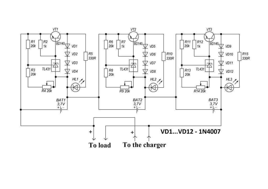 but this will only top balance and I don’t understand how to select the resistor values to make the cut-off 2.75V.
I’m wondering how to make a BMS to control charging and discharging a battery made up of LTO cells connected as 5S to give me approximately 12V.
I found something I hope can be easily modified at
Thanks for any help and advice you are able to offer
Thanks Tim,
You can use the following set up and adjust the preset accordingly for each module separately:
Good day Swag, how can I modify this circuit for 12v, 10A output. Thanks.
Hi Adeymei, you can do it by replacing the transistor in the last circuit with a 20 amp transistor
Hello Swagatam:
You mentioned that this device can goto 36 volt…I want to build a 36 volt supply to charge a 36 volt lithium iron phosphate pack. I have a 36 volt transformer, bridge rectifier, caps, tl431’s, and NPN power transistors rated at 60 Volt… i.e 2n3055. i am assuming I need to make the power circuit with a darlington configuration to drive the 2n3055 type.
Can you recommend using the tl431 at this upper voltage, or use a fixed zener?
Many thanks for your work.
Hello Lisa, a shunt regulator is not recommended for a transformer based supply, it is recommended for alternators or generators. Instead you can use a simple emitter follower circuit for charging your bats. as given below
Hello Swagatam..
I guess I was over thinking this… I will make this up and test it…
Thank You..
OK, no problem!
Please regarding your comments, I want to ask about the difference among trafo based charger, alternator and generator, as trafo affects shunt regulator.
I have used emitter follower system but it doesn’t regulate well as it shoots above level.
I have tried tl431 shunt regulator but for high voltage/current, 15v, 10amps, the tl431 gets very hot and burns without any negative effect on the transistor Please help to resolve these issues. Thanks Swag
For trafo based charger it is better to go for normal linear voltage regulators like LM338 etc, for alternators shunt regulator is recommended since it prevents high voltage rise in the alternator coil, and also keeps its frequency in control, but for trafo this may result in heating of the trafo.
Please where will I put the 12v regulator for the tl431 in the circuit. Thanks sir.
Adeyemi, Actually TL431 will never burn if the parameters are correctly calculated. Secondly an emitter follower will also never change is output if the zener diode is correctly installed on its base. Check your circuits again.
You can refer to the following article for more variations:
https://www.homemade-circuits.com/simple-voltage-regulator-circuits-using-transistor-and-zener-diode/
Thanks so much Swagatam for your response. I have tried few of transistor-zener regulators but I still prefer tl431 shunt regulator. It worked well for me in regulation but just that it got burnt as it can sustain at high voltage-current. Please help me out in getting the parameters right. Thanks
Adeyemi, the last circuit is the ideal shunt circuit for high current,you must calculate the parameters as per your requirement. The transistor must be appropriately rated to sink the excess voltage.
R=(Vi – 0.6)hFE / Load Current, for 15.5v input, and 10amps load current, please what will be R for base of the transistor. Please help to calculate the parameters. Thanks
Actually, the base resistor in the last circuit is not the biasing resistor of the BJT, since the BJT is a PNP. It is just to make sure the BJT base is held at positive switch OFF state as long as the input supply is below the maximum threshold.
You just have to calculate the other things in the circuit as explained through the various diagrams.
hi, what is the circuit efficiency? I want to use this as a powerbank, 2 lipo batteries. And also for power suppy charging 12v car batteries.
Efficiency is not relevant for this circuit since it is supposed to shunt and dissipate the excess power. If it is used for charging battery then the recommended source should be an alternator.
Please can you help with opamp based shunt regulator
The left side op amp stage is the op amp shunt regulator in the following schematic
https://www.homemade-circuits.com/solar-water-heater-with-battery-charger/
Hi Swagatam;
Referring the above “high current Regulator” section there is a PNP transistor and also there is a base reisistor there. However, we see positive voltage (from the V1) over that resistor to N base pin of the transistor.
So please explain how we can trigger the N base thru positive side? Thanks and regards.
Hi Suat,
In the “high current shunt regulator circuit”, the PNP transistor is not triggered through the base transistor, it is triggered by the conduction of the TL431 (cathode to anode and ground). The resistor is included to ensure that the base of the PNP is never in a floating state, and also to allow the TL431 to conduct efficiently.
Podemos inferir que esse resistor é de pull Down
Hi Mr. Swagatam;
On the 72V battery charger circuit; I would like to test the tl431 with the oscilloscope. Should I check the pins anode and cathode or ref. and cathode pins or both of them and also what kind of graphic image should be on the screen.
Hi Suat, you will see the cut off or the stabilizing voltage value across the anode, cathode of the tl431.
You must check ref. as well as anode cathode, all should depict the regulated voltage value of the ic…
Can TL431 work as a voltage level Detector? that is, it’ll conduct above a preset voltage, but won’t up to that level?
Yes, that is what it is designed for.
Hi Mr Swagatam;
On my charger circuit, the output voltaga as the 88,5V goes thru the 5K resistor to the cathode of the TL431. The measurement value as the follovings:
The voltage over the 5K resistor is about 85V. Cathode output voltage is about 5,5V and Reference voltage is about ,4V. Meanwhile I removed the above mentioned 5K with the 4K7 5W resistor since the former was defective and also removed the led driver IC (I think it is PIC16XXXX type) which is driven by the TL43 since it was defective too. At the moment I have the output voltage but still this 5K (or 4K7) is overheating. So I need your opinion please if possible?
Hi Suat,
The 4k7 is heating up because it has to dissipate overcurrent due to the excess voltage of 85 – 5.5 = 79.5V.
The only way to stop this is to use a higher value resistor such as 10k or 15k.
Thanks Swagatam,
Firstly I am sorry but reference voltage should be about 2,4V in my above message instead of ,4V because that some times my pc keyboard is out of order.
I have checked after your message the current consumption is about 18 mA for the 4K7 resistor. Is this current amount proper for the circuit or there is something wrong?
No problem Suat,
Yes the 18 mA is approximately correct if a 4.7k is used, but you may reduce it by replacing the 4.7k with a 10k and check the response, according to me it should still work.
I have temporarily placed additional 4K7 5W as serial since I do not have 10 or 15K with high watt value and now there is total 9K4 resistor and it seems very fine no overheating, gratefull.
That’s great Suat, glad it is working!
Thank you dear Swagatam for your post
I have questions about “Making a High Current Shunt Regulator using TL431” section:
1. How can I know “the magnitude of current the transistor is able to sink”, for example a TIP42C?
2. How can I know “the maximum tolerable current that can be sinked or shunted” by for example a TIP42C transistor?
3. You said “This can be calculated in the same way as discussed previously for the first TL431 regulator diagram”. Please explain how this can be calculated (for example) for a TIP42C.
Thanks in advance
Hi SA, thank for this interesting question.

For knowing how much current or power a transistor can handle, for example TIP42, you must look for something like this parameter in its datasheet:
Here you can see the figure 65 watts which is the maximum tolerable watts the transistor can handle as long as its TC = 25 degrees Celsius, meaning as long as its case temperature does not exceed 25 degrees C.
Theoretically TIP42 should be able to handle power that’s equal to collector/emitter voltage rating multiplied by collector current, 100 * 6 = 600 watts, but again this may be possible if you are ale to maintain its case temperature below 25 degrees Celsius, using massive heatsink and maybe water cooling etc, which may sound impractical.
Thank you for you answer Swagatam
You said “65 watts which is the maximum tolerable watts the transistor can handle as long as its TC = 25 degrees Celsius”. Then you said “Theoretically TIP42 should be able to handle power that’s equal to collector/emitter voltage rating multiplied by collector current, 100 * 6 = 600 watts”.
Given that TIP42 can tolerate only up to “65” watts (for example, 10.83 V*6 A= 65 watts), how can it handle “600” watts (for example, 100 V*6 A= 600 watts)?
Thank you SA,
Yes theoretically it can take 600 watts if you are able to keep its case temperature below 25 degrees Celsius, which is a big challenge, and almost impossible.
Hello again Swagatam
At the end of the Section “Making a High Current Shunt Regulator using TL431”, you said “The resistor at the base of the transistor is not critical and may arbitrarily selected anything between 1k and 4k7.”
Does not the value of this resistor and therefore the amount of current that flows to the Base of the transistor have any impact on the bahaviour of the transistor? If no, why? If yes, what is that impact?