In this post I will comprehensively explain regarding the various standard resistor color codes, and systems employed for assigning resistors their specific values. The post also explains how to read and identify resistor values from their color codes.
By: S. Prakash
The color codes used in resistors denote a leaded resistor’s value. These color codes of resistors have been used for a long time now.
The color code system used for the resistors is one of the most reliable and easiest methods for indicating the value.
This is true because at many occasions it has been observed that the values which are printed on the resistors are erased or obscured while transfer and handling of the resistors and thus identifying the values become difficult.
Basics of the color codes used in Resistors
The color coding on a resistor is done on the rings which the resistor has placed around itself and are colored.
The printing of figures or numbers on the resistor becomes difficult since all the leaded resistors are virtually of cylindrical shape.
Also, as discussed above, the usage and handling of the resistors can eliminate or obscure the prints.
In case, the coding scheme of the resistor is partially marked, the various rings present around it on which the color coding is dependent enables the deciphering of the various information related to the parameters and the values of the resistor.
The color coding systems which can be applied on a resistor is decided by the accuracy and the tolerance level which the resistor requires.
The color code systems used in various different resistors can be observed to be based on the same outline but the information which is provided by them is of different levels.
The major color coding systems which can be observed on a resistor are:
- Color code scheme of resistors consisting of four bands
- Color code scheme of resistors consisting of five bands
- Color code scheme of resistors consisting of six bands
The color code scheme in the resistors is provided on the basis of the number of rings which are being used by the resistor.
Color code scheme of resistors consisting of four bands
The series values for which the color code scheme of four bands is used are E24, E6, and E12 respectively.
The significant values which can be accommodated in this can range up to two figures.
The resistor accepts the values which are in range of maximum E24 along with the tolerance vale which is being accommodated by the resistor is in a maximum range of ±2%.
The color code scheme of the four bands of resistor provides information regarding various parameters of the resistors such as the temperature coefficient, value, and tolerance level.
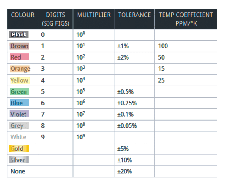
The name given to the band which is located closest to the resistor’s end body is “Band 1”. Out of the four bands, the resistor’s value’s significant figures are represented by the first two bands; while the multiplier is represented by the color code of the third band placed on the resistor.
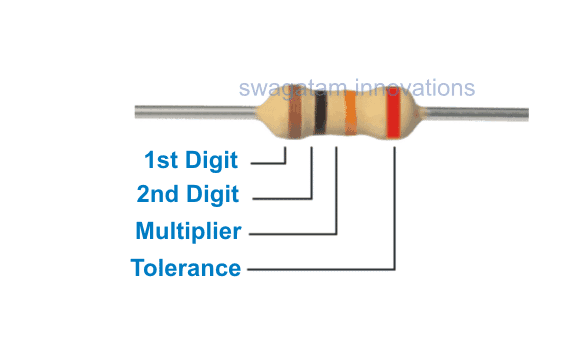
For example the color code scheme present on the above shown resistor consists of colors red, black, and orange along with a red band at the right side as the fourth band.
The first two color bands namely red and orange represent the significant figures of the resistor’s values which is 10; while the third color band orange represents the multiplier which is 1000.
The fourth color band which is red represents the tolerance level of the resistor which is ±2%. Thus, the value of the resistor can be interpreted to be 10,000Ω or 10kΩ.
Note: In case a resistor consists of only three color bands, then the first two bands will represent the significant figures of the resistor’s values while the third will represent the multiplier. The fourth color band representing tolerance will be absent here.
Color code scheme of resistors consisting of five bands
The color code scheme of resistors consisting of five bands is used for the series E192, E48, and E96 since these resistors require high tolerance levels which are in the range of ±1%.
Thus, in order to represent the significant figures of the resistor’s value, three bands are required and thus one extra band can be observed in this case. In all other sense, the color code scheme of resistors consisting of five bands is similar to that of the four bands only.
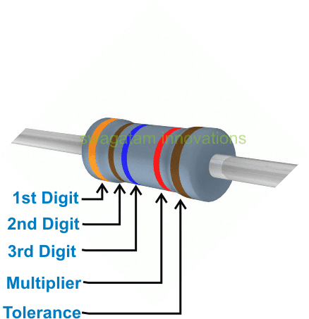
For example, the color bands present on the above resistor are orange, brown, blue, red, and brown.
The first three color bands represent the significant figures of the resistor’s value which is 316; and the fourth color band represents the multiplier of the resistor which is 100.
The fifth color band of the resistor represents its tolerance value which is ±1%. Thus, the value of the resistor can be written as 31.6kΩ or 31600Ω.
Color code scheme of resistors consisting of six bands
The color code scheme of resistors consisting of six bands provides the maximum level of information regarding the parameters of the resistor.
The series for which the color code scheme of resistors consisting of six bands is used are E192, E$*, and E96 respectively.
The color code scheme of six bands is used for the resistors which has tolerance values which are very high and in the range of ±1%.
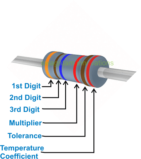
An example of the color code scheme of resistors consisting of six bands is shown above wherein the six colors on a resistor are orange, brown, blue, red, brown, and red.
The first three color bands present on the resistor represent the significant figures of the resistor’s value which is 316 while the fourth color band represents the multiplier which is 100.
The fifth color band represents the tolerance level of the resistor which is 1%. The sixth and the final color band represent the temperature coefficient of the resistor which is 50ppm/ºK.
Thus, the value of the resistor can be written as 31.6kΩ or 31600.
Color Code Chart for the Resistors
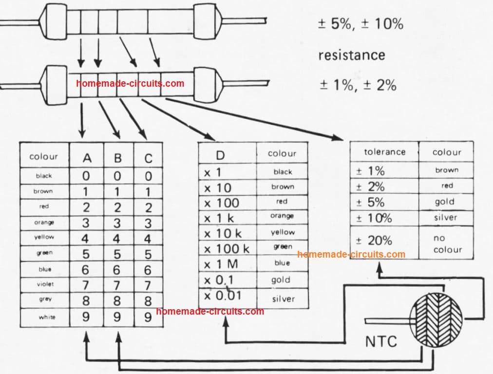
All types of leaded resistors which has approximately one watt of dissipation levels of power uses a color code.
Apart from this, the size of the resistors is sufficiently large and constructed accordingly in order to mark the various values and parameters in figures.
Thus, the leaded resistors widely use the colour code scheme. The color coding scheme of the capacitors is also based on basics of similar concept.


Questions & Answers
Dear sir,
I have two 1E/1W resistors. If i place both resistors in series i get 2E, here what happens to the wattage does it remain 1W or it changes,
similarly if i connected both in parallel i get 0.5E, here do i still have a 1W or is it different?
Dear Sherwin,
In series connection the resistors will show no change in their wattage, but in parallel their wattage will add up.