• Skip to primary navigation
  • Skip to main content
  • Skip to primary sidebar

Homemade Circuit Projects

Get free circuit help 24/7

  • +1000 Circuits
  • Hobby Circuits
  • Basic Circuits
  • Learn Arduino
  • Logic IC Pinouts
  • Disclaimer
You are here: Home / Electronic Components / High Voltage, High Current Transistor TIP150/TIP151/TIP152 Datasheet

High Voltage, High Current Transistor TIP150/TIP151/TIP152 Datasheet

Last Updated on January 1, 2020 by Swagatam 7 Comments

The TIP150, TIP151, TIP152 series are high voltage, high current Darlington transistors which can be used for applications involving voltages at mains 120V or 220V levels. The datasheet and other related details can be read in the following article.

The typical applications of this transistor could be for high voltage motor control, automotive ignition, inverter converter switching, SMPS and in many other similar areas.

Main Specifications

The main datasheet, specifications and features are as follows:

Collector to Emitter Continuous Voltage:
VCEO(sustained) = 300V minimum for (TIP150)
VCEO(sustained) = 350V minimum for (TIP151)
VCEO(sustained) = 400V minimum for (TIP152)
Collector−Emitter Saturation Voltage: VCE(sat) = 2V maximum at I current of 5A

The maximum current for the above voltages is 7 amps (continuous) and 10 amps for instantaneous peaks.

The base/emitter saturation voltage for TIP150, 151, 152 is 1.5V at 100mA for a typical 2 amp collector load, while it could be around 250mA at 2.3V for a 5amp collector load.
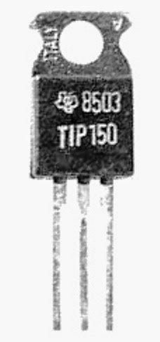
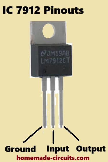
Pinout Details

In the shown image above the pinouts of the transistor can be identified as follows:

The center lead is the collector, it's connected with the metal tab of the device therefore the back steel tab also becomes the collector.
The right side lead is the emitter.
The left side lead is the base of the transistor.

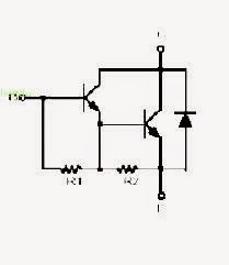
Internal schematic of the transistor TIP150/TIP151/TIP152

The above figure shows the internal Darlington structure of the transistor. A typical paired transistors could be seen here which forms the Darlington configuration.

This configuration helps to provide the device with extremely high gain and sensitivity even at the specified high power inputs.

SHARING IS CARING!


Previous: Fading an LED ON/OFF – Arduino Basics
Next: Tilt Sensor Switch Circuit

About Swagatam

I am an electronic engineer (dipIETE ), hobbyist, inventor, schematic/PCB designer, manufacturer. I am also the founder of the website: https://www.homemade-circuits.com/, where I love sharing my innovative circuit ideas and tutorials.
If you have any circuit related query, you may interact through comments, I'll be most happy to help!

You'll also like:

  • 1.  IC TDA 7560 Datasheet – 4 x 45W QUAD BRIDGE CAR RADIO AMPLIFIER PLUS HSD
  • 2.  220V Solid State Relay (SSR) Circuit using Triac and OptoCoupler
  • 3.  How Electret Microphones Work – Full Tutorial and Diagram
  • 4.  Understanding Capacitor Codes and Markings
  • 5.  How to Use Transistors
  • 6.  Modifying XL4015 Buck Converter with an Adjustable Current Limiter

Please Subscribe (Only if you are Genuinely Interested in our Newsletters)


Reader Interactions

Comments

    Your Comments are too Valuable! But please see that they are related to the above article, and are not off-topic! Cancel reply

    Your email address will not be published. Required fields are marked *

  1. Search Related Posts for Commenting

  2. Jideofor Igwe says

    The inductor is about 330uH. The battery is 3.7v 1200mah. I used the concept of the 1.5v to 12v converter i found in your site here. The two transistors are BC548-558(complementary). But i want to use 4×1.5v in parallel.

    Reply
    • Swagatam says

      the 330uH coil should be rated at 1 amp, meaning the wires guage should be at least 0.8mm and the transistors should also be rated equally, 2N2222/2N2907 could work.

      Alternatively you can try the following design if the previous circuit does not give appropriate results:

      https://homemade-circuits.com/2012/10/1-watt-led-driver-using-joule-thief.html

      Reply
  3. Jideofor Igwe says

    Ok. The joule thief cellphone charger i produced was discharging instead of charging the phone. Please what could be the problem. And if i use L7805 with it, the current output will drop to 10mA. My phone needs atleast 800ma to charge. Please help

    Reply
    • Swagatam says

      provide me with all the details about the circuit, only then i would be able to suggest correctly.

      provide the coil details and the battery details

      Reply
  4. Jideofor Igwe says

    Please sir, i have a 650VA UPS that is powered with a 12v, 7AH rechargeable battery. Is it possible to charge 50 cellphones at once with this UPS? If not, how many cellphones can it charge at once?

    Reply
    • Swagatam says

      50 cell phones would consume 0.2 x 50 = 5amps of current while charging, your battery would get discharged within half an hour so it's not feasible in my opinion.

      Reply
    • Swagatam says

      ….oops sorry 0.2 x 50 = 10amps, now it looks impossible…

      Reply


Primary Sidebar

Electronic Projects Categories

  • 3-Phase Power (15)
  • 324 IC Circuits (19)
  • 4017 IC Circuits (51)
  • 4060 IC Circuits (25)
  • 555 IC Circuits (94)
  • 741 IC Circuits (18)
  • Amplifiers (49)
  • Arduino Engineering Projects (82)
  • Audio Projects (85)
  • Battery Chargers (76)
  • Car and Motorcycle (88)
  • Datasheets (45)
  • Decorative Lighting (Diwali, Christmas) (32)
  • DIY LED Projects (82)
  • Electronic Components (97)
  • Electronic Devices and Circuit Theory (35)
  • Electronics Tutorial (100)
  • Fish Aquarium (5)
  • Free Energy (34)
  • Games (2)
  • GSM Projects (9)
  • Health Related (17)
  • Heater Controllers (24)
  • Home Electrical Circuits (98)
  • Incubator Related (6)
  • Industrial Electronics (27)
  • Infrared (IR) (39)
  • Inverter Circuits (94)
  • Laser Projects (10)
  • LM317/LM338 (21)
  • LM3915 IC (24)
  • Meters and Testers (55)
  • Mini Projects (153)
  • Motor Controller (65)
  • MPPT (7)
  • Oscillator Circuits (15)
  • PIR (Passive Infrared) (8)
  • Power Electronics (33)
  • Power Supply Circuits (65)
  • Radio Circuits (9)
  • Remote Control (46)
  • Security and Alarm (56)
  • Sensors and Detectors (116)
  • SG3525 IC (5)
  • Simple Circuits (72)
  • SMPS (29)
  • Solar Controllers (60)
  • Timer and Delay Relay (51)
  • TL494 IC (5)
  • Transformerless Power Supply (8)
  • Transmitter Circuits (39)
  • Ultrasonic Projects (12)
  • Water Level Controller (46)

Follow Homemade Circuits

Facebook
Twitter
YouTube
Instagram
My Facebook-Page
Quora

Feeds

Post RSS
Comment RSS

Circuit Calculators

  • AWG to Millimeter Converter
  • Battery Back up Time Calculator
  • Capacitance Reactance Calculator
  • IC 555 Astable Calculator
  • IC 555 Monostable Calculator
  • Inductance Calculator
  • LC Resonance Calculator
  • LM317, LM338, LM396 Calculator
  • Ohm’s Law Calculator
  • Phase Angle Phase Shift Calculator
  • Power Factor (PF) Calculator
  • Reactance Calculator
  • Small Signal Transistor(BJT) and Diode Quick Datasheet
  • Transistor Astable Calculator
  • Transistor base Resistor Calculator
  • Voltage Divider Calculator
  • Wire Current Calculator
  • Zener Diode Calculator
  • Privacy Policy
  • About Us
  • Contact
  • Disclaimer
  • Videos – Circuit Test Results

© 2021 · Swagatam Innovations