In the following post I have explained the main technical features and specifications of 3 watt white LEDs. I have explained more regarding their operating parameters and safe-operating limitations.
Main Features
- Extreme luminosity capability
- Extreme working life > 50K hours.
- Very Low thermal resistance.
- SMD technology allows embedded PCB type sodering.
- Completely UV free design
- Enhanced ESD protections
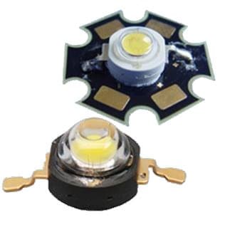
Image Courtesy - https://www.led-display.cc/High-Power-LED/Q1B/LP5W-80-SERIES:-5-watt-high-power-LED.jpg
The soldering details and dimensions of a typical 3 watt LED may be checked in the following diagram:
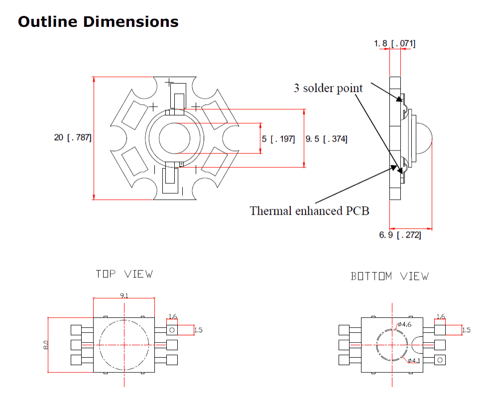
The dimensions are in millimeters.
The anode side of the LED can be identified by the given hole on that particular side.
The PCB heatsink pad must be tightly in contact with the body metal or the slug of the device. Remember the body metal is neutral and has no connection with either the anode or the cathode of the device, and must not be linked with any of the leads of the LED.
The lens of the device is sensitive to rough cntacts so excercize caution not to brush any hard or shrp material with the lens which might considerably reduce the light intensity from the LED
Technical parameters of the device:
Luminous Flux - 100 to 120 lm
Forward Voltage - 3.3V to 4 V maximum. These are the minimum and the maximum limits for operating the LED.
Optimal viewing angle - 90 degrees.
Absolute Maximum Ratings
These are the values which indicate the extreme limits of the relevant parameters above which the device might get instantly damaged.
Forward Current - 1 ampere
Power Dissipation - 4 watts
Junction Temperature - 125 degrees Celsius
Operating temperature - minus 30 to 85 degrees Celsius
WARNING - THE EXPLAINED 3 WATT LED SHOULD BE OPERATED WITH THE ABOVE PARAMETERS ONLY AFTER MOUNTING IT OVER A SUITABLE HEATSINK FACILITATED PCB. THE DEVICE WILL NOT WITHSTAND THE OPERATIONS FOR MORE THAN 5 SECONDS WITHOUT A SUITABLE HEATSINK ATTACHED TO ITS BODY.
Courtesy - https://www.futurashop.it/pdf_eng/8220-L-HP3PW.pdf

Questions & Answers
bem legal, procurava em alguma página no Brasil informações mais precisas desses leds e acabei achando aqui.
utilizando um regulador LM 317 e alguns resistores, liguei os LEDs em um farol de milha da moto e ficou muito bom, precisava saber dados técnicos como tensão, corrente, e temperatura de trabalho desses LEDs, graças as informações encontrada aqui, tudo funcionou perfeitamente.
obrigado.
Estou feliz que você gostou, por favor, mantenha o bom trabalho!
1) I have 3 X 3W LEDs, how many LEDs can i conncect to USB charger power? which ohms risistor i need?
2) How many 3W LEDs can i connect to 9V HW battary (series / Parallar)? which ohms risistor i need?
assuming the voltage rating of the LED is 3.3V, then
R =5 – 3.3/0.9 = 1.88 ohms or 2 ohms, and wattage is 2 watts
a PP3 HW 9V battery will not illuminate any high watt LED due to low current
Hello sir I have 12V 2amp smps adapter so i want to run 1watt leds on that so how many leds can I use on it
..sorry with 2amp current you can double that, that is connect 4+4+4+4 = 16 LEDs total…
hello basit, you can connect 8 LEDs in all, made by connecting two strings of 4 LEDs in parallel…a 1 ohm/1watt resistor must be included with each of the series…
Hi sir, regarding 1 watt Led what would be approx cost , i dont know over my place its avail are there any online sites for purchasing? also as a beginner i want to know much about these.
i have heard that 1 w led should not be exposed to eyes , leaving blind this can cause permanant damage to eyes?
voltage is normally 3.3V and current 300mA, even though it has a base an external heatsink is recommended .
Thank you very much sir. one more question 1w led has 9mm base diameter? what would be the current & voltage rating? i got an led saying its 1w having 9mm , like an ordinary led but bigger without any need of HEAT SINK.
Hi Rohith, buying online could be risky and time consuming, you should go to your nearest electronic retailer and ask him regarding it.
Yes 1 watt leds are particularly extremely bright which could cause temporary blindness, and headache if looked directly into them while illuminated.