Transcutaneous electrical nerve stimulation (TENS) is a term typically referred to the use of nonpharmacologic or noninvasive kind of treatment for neutralizing superficial pains.
How Transcutaneous electrical nerve stimulation Works
Researches have shown that TENs helps to control pain both over peripheral and also central mechanisms.The central mechanisms include areas of spinal cord and brainstem that are known to incorporate opioid, serotonin and muscaranic receptors which could be effectively stimulated using TENS implementation.
Across peripheral areas TENs may help induce analgesic effects on receptors such as opioid and alpha2
noradrenergic.
The process involves application of very low DC low frequency pulses through electrodes on the patients skin surface for activating the intended pain control.
The method could tried by applying different frequency ranges from as low as 10 Hz up to 50 Hz.
The circuit may be tried with on two modes the first being in the sensory intensity mode where the patient is able to feel strong effects but without motor contraction sensation, and the second is through high intensity mode in which the motor contractions are induced but without any relative pain or strong sensations.
Typically the high intensity mode is implemented through a high frequency stimulation while the motor intensity is done through a relatively lower frequency electric current.
However researches have indicated that the analgesic effects may be released through any of the above modes regardless of the frequency intensities or variations.
To be more precise, a low frequency TENs may be responsible for initiating the μ-opioid receptors in the spinal cord and brain stem, while a higher frequency TENs could be used to give rise to the activation of δ-opioid receptors around the same areas.
Further developments suggest that the application of TENs may effectively relieve pain due to the actions of serotoninergic, noradrenergic, muscarinic, and γ-aminobutyric acid (GABA)-ergic systems
on the analgesia with the application of both low or high frequency TENs on a patients skin.
You may also want to read about this electronic acupuncture concept
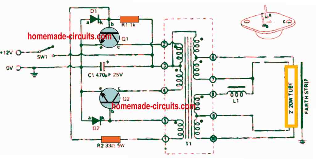
A simple Transcutaneous Nerve Stimulator Circuit may be witnessed in the above figure, using the work horse IC 555 configured in its standard astable mode
P1 is used for producing several ranges of frequency outputs in conjunction with a variations in the pulse widths of the output frequency for the implementing the above explained TENs procedures T1 is used for producing TENs at the level of the supply voltage for acquiring maximum effectiveness.
The transformer could be any ordinary radio output audio transformer or made by winding 10:100 turns 36 SWG super enameled wire on a small EE ferrite core.
The output of the transformer could be arranged in the form tiny protruding copper prods, not too sharp but sufficient enough for creating a slight digging impression on the skin and may be wrapped on the affected area with some suitable cohesive band.
2) TENS Circuit for Multiple Nerve Stimulation
The following circuit was requested by one of the dedicated visitors of this blog, as given below:
"I am looking for a circuit solution to perhaps utilize a pair of bar/dot graph display IC's and to take each triggered output and transform this output to a voltage sufficiently high to stimulate nerve endings .
The nerve endings are connected via a conductive needle ( stainless steel) making intimate contact with said nerve endings. I have suffered by convulsive 'jumping' of my legs when I relax and when I am in bed.
I have been to a number of specialists without them being of any assistance. I have been reading about T.E.N.S. and believe that this could be worthy of an experiment. There are apparently many people world wide suffering from this complaint.
My thoughts are that if I feed a variable signal of low amplitude into the nerve ending that the continual low stimulation might override the large pulses which cause instant muscle contraction. I believe that this is worth a try."
Circuit Diagram
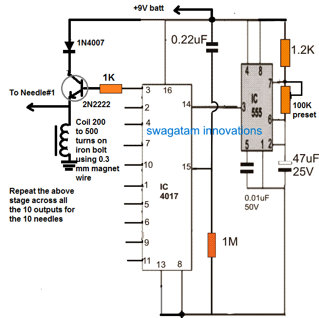
The circuit is based on a simple IC 4017 and IC 555 sequential dot mode driver circuit. The output of the IC 4017 create a running or sequencing high logic pulse across its 10 outputs in response to the clocks generated by the IC 555 astable at its pin#14. Each of these outputs are configured across a transistor/inductor circuit which act like a small boost converters, and convert the 9V pulse into a low current 100V or 120V short pulses.
The indicated ends could be integrated with 10 individual needles for the required transcutaneous stimulation across the intended muscle areas.
The pulse width and frequency can be controlled by adjusting the 100k preset.
Warning: The coil dimension and voltage presented above are assumed values only, and have not been confirmed. Serious experimentation may be required through qualified medical engineers before implementing the device practically.

Questions & Answers
hi there Swagatam.. good day.. Spencer in South Africa.
I now am 76 years old… and I have now unfortunately suffering from the DRY MOUTH problem.What this means is a great deal of a problem. I used to be able to enjoy a simple lemon tea.. hot .. with a baked rusk..!! I no longer can do that. I used to enjoy a simple coca cola … but no longer can do that either.. I am not as far as the GP has tested any diabetic of any type… If you read it up.. DRY MOUTH PROBLEMS.. you will find it a really nasty affliction to have.. If the weather changes.. becomes damp or cold.. I really also battle to sleep.!! because when you sleep.. you naturally most times.. default to breathing through your mouth. This destroys your .. chances.. as if you awake suddenly.. you notice that your tongue is stuck horribly to the side or roof or wherever in your mouth.!! you have to make sure that your nasal passages.. are as clean as a whistle..!! so that you can attempt to draw air into your lungs through your nose.!! so the reason that I am writing to you is that some research papers written by researchers claim that it is possible to use a TENS unit with conduction pads.. stuck to a clean part of the face over the area of the PARTOID GLAND.. ! Inside your face like about somewhere there is a SALIVARY gland.. which sposed to like ‘water’ and this is the saliva which your digestion system needs.. In my case .. apparently in old age.. this is quite common.. and I am studying it now with great haste.. as I am very desperate to solve this problem, and get some way. If you go and read it up now.. you will be shocked and horrified at what is going on.. I have to like some nights .. almost never have any sleep.! because if the weather is not nice.. cold and wet.. it affects my whole constitution and means that I probably will never get enough rest. I cannot eat any nice cakes anymore.. since they as full of sugar. If the food has condiments and spices and salts.!!!!! FORGET IT.!!!
You can go ahead and study it.. The research papers from the UK and India .. are using TENS devices.. !! All I know is that there are frequencies .. very low like 2 to 4 cps … and then 50 Hz and then also 80 Hz and maybe 100 Hz.. I am desperately trying to.. find information on the output voltages.. of commercial TENS devices.. and also whether they as SINE waves or SQUARE waves.. I have shares in GOOGLE GEMINI.. by now.. like I would ask.?? may I eat red peppers.. or eat mielies on a cob.. and GEMINI would report.. back. this is not good because of this and that etc etc. I used to enjoy an egg.. a plain unadulterated soft boiled egg.!! but now all of a sudden I get a protein allergy.. and my dry mouth is all on fire.!!!
I would love you to help me.. please.. so that I could attempt to.. design a worthwhile unit which produces .. the correct output signals.. so that I might try it on my PARTOID GLAND up the side of my face… just google and gemini should be able to help.. you locate its position..
Anyway SWAGATAM have a good christmas 2025 – GOD BLESS..!! and I will pray for you to get some good circuit working.!
apparently the PARTOID GLAND is one of the main salivary glands in your face.. If I could at least just attempt to construct a TENS unit that would work then possibly I could sleep with the pads on my face.. and hope that enough saliva could be excreted.. for during the sleep time hours. I have to have a continual small ice block supply.. that I can continually sip on to keep my tongue wet.. or moist.!!
If anyone else reading this – knows of a cure – please share with us.!
I just want to tell all and everyone.. when I was about 26.. TWO CARD READERS.. told me that in my 70’s / early 80’s .. I would develop some tech gadget that works with water.!! and it would make me the most wealthy guy in the world.!! I still do not know – what that tech gadget is.. but hey man.. I not interested in the MONEY.. if it has to do with Xerostma.. then by jingos.. lets do it.!!
thanks SWAGATAM …
Hi Spencer, very good day to you, and thank you so much for explaining everything in detail. I am really sorry to hear about your dry mouth trouble. We can understand how difficult this thing becomes when you try to sleep or even eat simple food.
From what we see in different research papers, many doctors are testing normal TENS type electrical stimulation over the parotid gland area for helping the saliva nerves. The papers mostly use simple pulsed electrical signals, normally around 50 Hz to 100 Hz pulsed frequency, with a small pulse width, and the output is mostly a gentle square-type pulse, not a sine wave. The current level is always kept only to a mild tingling feeling, never painful. The electrodes are always kept outside on the skin area just in front of the ear where the parotid gland sits, but I must say that you should always take guidance from a doctor before you try anything like this on your face.
So you can first talk with your GP or dentist and ask them whether a normal physiotherapy TENS trial is safe for your situation. Many clinics already use these units so they can guide you about pad placement and safe intensity. If the doctor gives a green signal, then you can test a ready-made TENS unit first. After that, if it helps you a little, then you can think about designing a small circuit with the same frequency and pulse pattern used in those studies, as given below….
Please take care of your nasal passage also, because that helps you a lot during sleep. You can also keep sugar-free lozenges or dentist-recommended saliva substitutes near you, so that your mouth stays moist when the weather becomes cold and damp.
God bless you too, and Merry Christmas in advance!
Agreed. Collector side coils w/flyback and over voltage protection would work just fine. My understanding is that effective TENS voltages can get quite high (no known citations, but estimate >100v) so a high VCE rated transistor is advisable.
That makes sense, thanks for your valuable feedback.
The multiple nerve circuit (2nd one) does not look like it would work. When the transistor attempts to turn off the inductive kick will pull the transistor emitter well below ground causing the base to pull current from the driver chip and turn back on, mitigating the pulse. Several of the other transformerless circuits would seem to have insufficient drive voltage. Did I miss something?
I am unable to simulate your explanation. However, I have seen relays being used at the emitter of a transistor with freewheeling diode to protect the transistor. If the relay coil can produce an inductive spike, the above coil can too. Nevertheless you can shift the coil to the collector side of the transistor.
Pouvez-vous envoyer un simple circuit du l’électrostimulateur ?
Il ya d’une etude electrique des filtres et quel le type de la filre et la fonction de transfert H(p)=? dans le cercuit de TENS et aussi le shema bloc ?
Sorry, I have no idea about this information.
I think I asked the wrong way. I meant I wanted an electric circuit for an electrical stimulator, with information about the electrical tension and current, the equations that combine them, and also the circuit differential equations, please.
I understood your question, however I do not have a detailed information about all those parameters that you have mentioned.
This is a very resourceful website. Thank you for creating this information. I had two questions about the very first circuit on this page.
1. Can it be modified to deliver tetanic stimulation, with variable current of up to 70 mA (This is because patient impedance can be variable, so there needs to be a way to do the same), and if so, which components would need to be modified (or added)? I initially thought it could be as simple as changing the transformer, but my simulations in LTspice (happy to share the file) indicate otherwise.
2. Same question for frequency, can it be modified to deliver tetanic stimulation for frequencies ranging from 80 to 100 Hz?
Any insight would be appreciated.
Thank you again 🙂
Thank you for liking this website, however since I do not know much about tetanic stimulation it is difficult for me provide any useful suggestion on this topic.
Thank you for the quick response. Tetanic stimulation is just a fancy name for a series of impulses, when a switch is pressed. For example, current impulses of amplitude 30 mA, with frequency 100 Hz, would just be a signal that is composed of a bunch of spikes that are 30 mA tall and separated by 10 ms…. The load on the secondary of the transformer would be patient skin impedance…. Hope that helps.
OK, in that case it could be perhaps implemented in the following manner:
You can also try the other output pinout combinations to produce various different sets of pulsed frequency sequences.
Thank you for the prompt response. I will definitely try it out. Thanks again for maintaining this website 🙂
It’s my pleasure!
What should be the frequency supplied to Transformer.
Good day Swagatam,
I am a quadriplegic and recently came across some research using a stimulator externally on the neck to enable the use of paralyzed hands. It uses 10Khz at 90 miliamps. The researcher will not give out any more details.
Can you help me with a circuit diagram for such a device?
Thank you
Andy
Thanks Andy, the data that you have provided can be very easily adapted in any oscillator circuit for the intended results, however the voltage spec is not provided which can be a very crucial element for this application. So if could get the voltage data, then I could quickly design an appropriate circuit for you.
Thank you.
I have not had success finding out the voltage. I can only assume the voltage is the same as any muscle stimulator.
I did find the official paper which gives the following detail:
https://www.homemade-circuits.com/wp-content/uploads/2021/02/spinal-chord-stimulation.pdf
OK, if the TCS voltage can be same as the DC supply to the circuit, then probably it can be implemented simply through a IC 555 circuit as shown below:
The pot can be used for optimizing the pulse duration, while the 1nF capacitor could be experimented with to get the most effective frequency output.
The output pin3 1uF capacitor and the 1k could be totally eliminated and the output pin3 could be directly used for the TCS to get stronger TCS effect.
Thanks. I will digest
Hi Swagatam, I am from Thailand . We would like your support to modify standard TENS circuitry to be our customized output in term of frequency and current . Frequency will be as higher as 1MHz while current output will be as low as microAmp.
If we send you our parameter or specification ,would you help us ?
Hi Don, please also specify the voltage level specification for your requirement
Hi Sawgwtam, Thks for reply . We sent via your email . Kindly look into that and advise.
Much appreciate your support …Don
Hi Don, sorry I could not find any email from you, if possible you can provide the voltage spec here, I’ll try to solve it for you!
I sent voltage output via email again. Thanks for your support.
Don
OK, here’s a simple design that you can try which will fulfill your basic TENs specifications:
Let me know if you have further doubts
yes I saw it, I’ll try to do it soon…
I just resend it. Can you recheck .?
Many thanks for your support.
Don
The required voltage on the probes is not mentioned in your specifications!
OK, I got your email. I will check it and respond here, through comments, regarding the solution and the diagram.
Hi Swagatam,
I am enquiring re. your multi output TENS. If I wanted to build 10 x output I take it I need 10 each of (1N4007, 1K pot., 2N2222, inductor coil). I am wanting this as an acupuncture needle stimulator where outputs have alligator clips on ends, 2 per output, which I assume is (+) and (-). On the older unit I have, there are 4 x outputs adjustable, so can be connected to 8 needles. Your to needle #1 output, is this a single (+) output, where is the (-) ? How do I connect a 1 in 2 out wire ?
I am a Chiropractor/Acupuncturist in Qld, Australia.
Hi Greg, yes you can take divide the output from the transformer into 10 separate terminals for your application. The transformer can be any standard 0-6V, 120V or 220V, 500 mA, or 100 mA transformer.
The output can taken directly from the secondary wires of the transformer used in the circuit. The same wires can be used in parallel for all other needles also.
However, you will have to test the intensity of the pulses to ensure that it is not dangerously high for the patient….
Hello sir khalid here thankyou very much for your help and and reply. I try pot 5k having with me later i will 10k but its work good now its goving very dlight shock but for c2 what should be the cap value so i will put 10kpot and will back to you for final result thanks a lot please reply.
You are welcome Khalid, C2 value can be as per your preference, depending on how fast you want the output pulses to be.
hello sir thankyou very much for reply sir khalid here i put 10k between collecter and transformer now the shock is 0 i touch prods doesnt feel anything i changed c2 with 100uf 22uf and 10uf but doesnt feel anything on prods and 0.22uf still connected in seiries with ic pin3 and base .i think very small shock os must for simulater so what we have do now or we can reduce the value of 10k resister and try .please need your suggestion please reply waiting fir reply thanks.
Hello Khalid, To get a feeble tingling sensation you may keep decreasing the 10k util you get the effect.
You can use a 10 preset instead of a resistor, and adjust it until the result is achieved
Hello sir khalid here Thankyou very much for reply and you are a genius and very very kind person you giving us skills thank you very much sir i put 06v 500ma transformer yes its goving shock and finally what should be value c2 cap 100uf or 1uf or 0.1uf for this 220v 06v 500ma transfomer the circuit working perfect and i want enclose with some small encloser so waiting to know the value for cap c2. thanks please reply to complete this project.take care.
That sounds great khalid, glad you finally accomplished the required results. Lower value capacitor will cause the frequency to increase generating a continuous 220V AC at the transformer, while increasing the capacitor will generate the same in a short pulsed form….so it will depend on your application requirements.
By the way you can reduce the capacitor and still get low pulsed frequency by adding an appropriately calculated high value resistor in series with the 1k resistor.
But remember this 220V is strictly not recommended for skin stimulation. You may try reducing the impact by adding a 0.22uF capacitor in series with the transistor base.
Hello sir khalid here thankyou very much sir for reply i checked with 100uf the led working good on short pulses and brightness high led working good i replaced transformer with led but transformer not work and for transformer output i connect neon led its not not work . And i connect instead of transformer a neon led bulb with diode and groung in place of transformer but the neon bulb good.so whats your suggestion please need help waiting for your reply thanks.i will be back with result.
Hi Khalid, use an ordinary step down 0-6V/500 ma 220V or 0-12V 500mA/220V transformer and check the response, it will give little electric shocks at the 220V side, if it does then your previous transformer could be faulty.
Hello sir khalid here thankyou very much for reply sir you are genius and very very person you are spread the skills allover to efucate peoples like me thankyou god bless you. Sir i replace c1 to 100uf the led blinking so what next the transgormer should be audio transformer or what because i tried 500 tons gor input and 10 tons gor output but not work what your suggestion sir please reply waiting for reply thanks.
Hello khalid, if the LED is blinking with a 100uF capacitor that means your IC 555 is working OK.
Now with this same LED set up, try varying the pot, and check whether it creates different blinking rate on the LED, in terms ON/OFF time…this will prove that the PWM control is working OK.
Once this is confirmed, you can replace the 100uF with a 0.1uF or try smaller values such as 0.01uF, and check the response on the transformer.
Make sure to use a 9V power supply input for the the circuit and not a 9V battery.
Also replace the BC557 with a 8550 or 2N2907 etc.
And, keep an LED connected in series with the transistor base line to provide prefect OFF switching for the transistor….LED cathode will go toward the pin3 of the IC, and anode towards base of the transistor.
Additionally, connect a 1k across the base/emitter of the transistor.