The IC 555 timer is a popular and adaptable integrated circuit that has established itself as a standard in the electronics industry. It is a well-liked option for DIY and educational projects thanks to its straightforward design, inexpensive price, and simplicity of accessibility. The IC 555 timer, which can produce a variety of waveforms including square, triangular, and sawtooth waves, is a crucial part of many electrical circuits.
What is IC 555
IC 555 is a type of integrated circuit that is commonly used in electronics projects as a timer or oscillator. It was originally presented by Signetics in 1971 and since then has grown to become a popular solution for a variety of applications.
The IC 555 is made up of several components including comparators, flip-flops, and a voltage-controlled oscillator. Collectively, these parts provide a flexible timing circuit that may be set up in several ways.
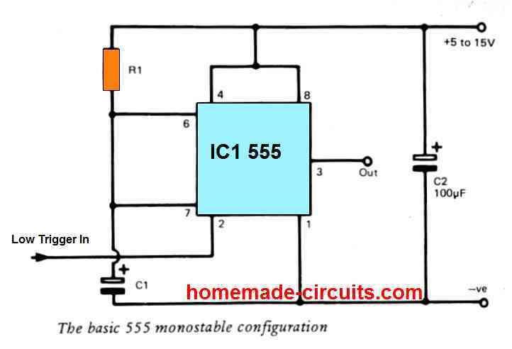
One of the most common uses for the IC 555 is as a monostable or one-shot timer.
In this configuration, a trigger pulse is used to activate the timer, which then produces a single output pulse of a specific duration. The formula for calculating the duration of the output pulse is:
t = 1.1 x R x C
In this equation,
- t is the duration of the output pulse in seconds,
- R is the resistance in ohms of the timing resistor,
- and C is the capacitance in farads of the timing capacitor.
Another common configuration for the IC 555 is as an astable or free-running oscillator. In this configuration, the IC 555 produces a continuous square wave output signal.
The following formula may be used to determine the frequency of the output signal:
f = 1.44 / ((R1 + 2 x R2) x C)
In this equation,
- f is the frequency of the output signal in hertz,
- R1 is the resistance in ohms of the first timing resistor,
- R2 is the resistance in ohms of the second timing resistor,
- and C is the capacitance in farads of the timing capacitor.
Overall, the IC 555 is a versatile and widely-used integrated circuit that is useful for a variety of applications in electronics.
In this article, we provide a thorough collection of widely used IC 555 circuits and projects. This page includes a variety of projects that DIY enthusiasts and students may readily do, from basic timer circuits to more complicated applications like PWM circuits and tone generators.
Each project comes with a thorough circuit diagram, tutorial, and explanation to assist readers understand how the circuit functions and how it may be altered to meet their individual requirements.
So let's plunge in and discover the fascinating world of IC 555 circuits and projects!
DC Light Dimmer Circuit
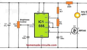
The article provides a circuit diagram and explanation for building a DC lamp dimmer using the IC 555 timer.
The circuit uses a potentiometer to control the duty cycle of the 555 timer, which in turn controls the average voltage supplied to the lamp, thus dimming it.
In this article I have explained the working principle of the circuit, component selection, and circuit modifications that can be made to adapt it for different loads.
It also provides a list of materials required and step-by-step instructions for building the circuit.
Astable Multivibrator Circuit
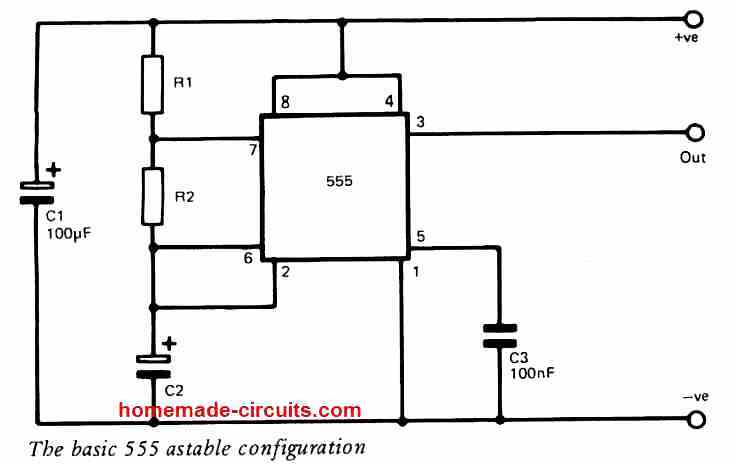
In this article I have explained the operation and construction of astable multivibrator circuits using the IC 555 timer.
The article begins by introducing the basic principles of astable multivibrator circuits and how they operate using a capacitor and resistors to create a square wave output.
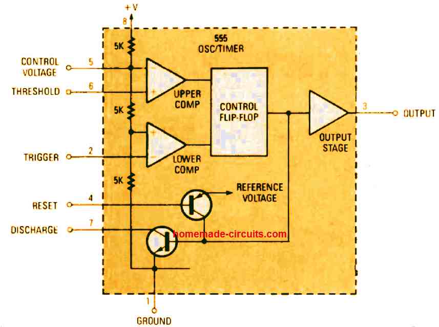
The article then goes on to describe the internal block diagram of the IC 555 timer and how it can be configured to operate in astable mode.
Several astable multivibrator circuits are then presented with different component values and configurations, including the standard astable multivibrator, the missing pulse detector, and the pulse position modulator.
The article includes circuit diagrams, component lists, and detailed explanations of how each circuit works.
The article also covers practical aspects of building astable multivibrator circuits, including choosing appropriate component values, calculating duty cycle and frequency, and using the IC 555 timer in conjunction with other components such as transistors and diodes.
Overall, the article is a comprehensive guide to astable multivibrator circuits using the IC 555 timer, suitable for beginners and advanced electronics enthusiasts alike.
Visitor Counter Circuit
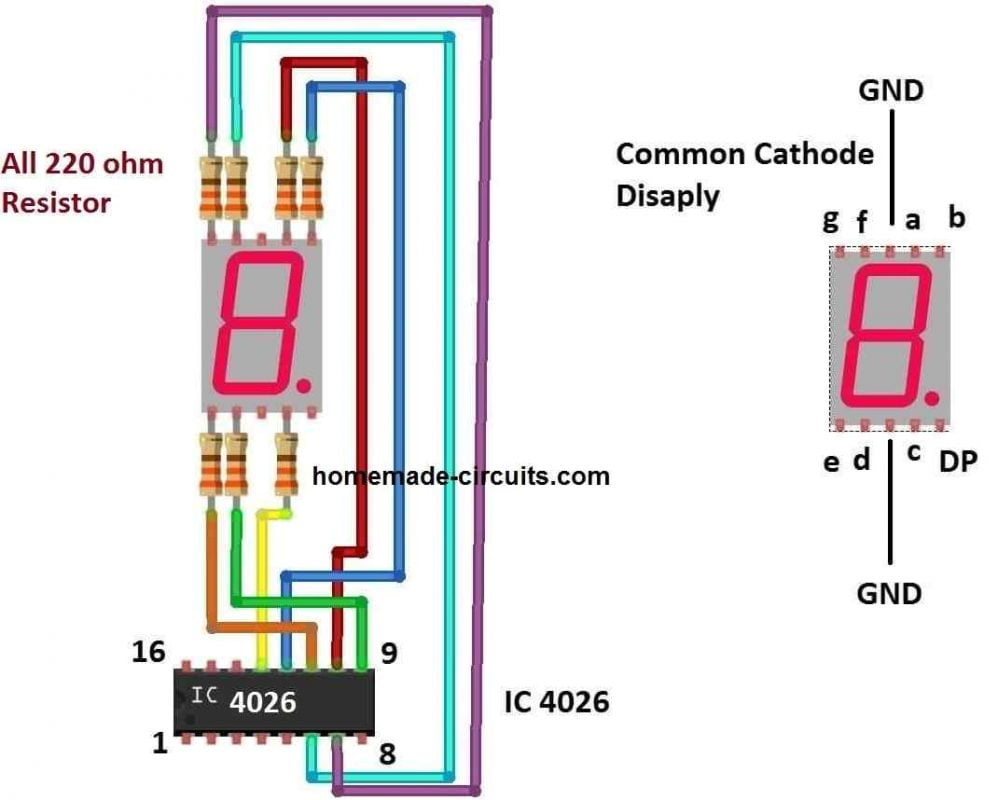
In this article I have explained a visitor counter circuit that can be used to count the number of visitors entering a room, building, or any other space. The circuit is built using two integrated circuits (ICs): the 555 timer IC and the 4026 decade counter IC.
The circuit works by using a couple of infrared (IR) sensors which are positioned at the entrance and exit points of the premises being monitored. When a person passes through the entrance sensor, it triggers the circuit to start counting. As the person passes through the exit sensor, the count is incremented by one.
The 555 timer IC is used as a clock generator that generates pulses at a regular interval. These pulses are fed into the clock input of the 4026 decade counter IC, which counts the number of pulses and displays the count on a seven-segment display. The display can be reset to zero using a reset button.
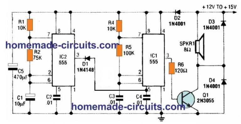
Siren and Alarm Circuits
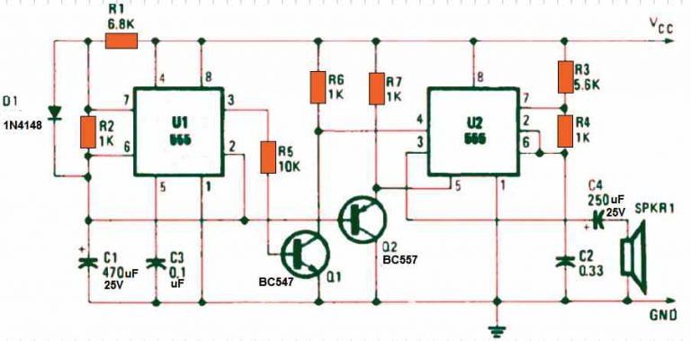
In this article I have explained several different circuits that use the 555 timer IC to generate siren and alarm sounds.
The 555 timer IC is a flexible and popular integrated circuit that may be used to build many oscillator and timing circuits, such as those used in sirens and alarms.
In this article I have explained a few straightforward electronic circuits that may be built using resistors, capacitors, transistors, speakers, and a few other widely available electronic parts.
One of the circuits described is a basic siren circuit that produces a rising and falling tone when triggered. The circuit uses a 555 timer IC in astable mode to generate the tone, and a transistor to drive the speaker.
By adjusting the resistance and capacitor values in the circuit, the tone frequency and intensity may be changed.
Another circuit described in the article is a burglar alarm circuit that uses a 555 timer IC in monostable mode. When triggered, the circuit produces a loud alarm sound for a set period of time before automatically resetting. The circuit includes a trigger input that can be connected to a sensor or switch to detect unauthorized access.
Other circuits described in the article include a simple door alarm circuit, a water level alarm circuit, and a fire alarm circuit. Each of these circuits uses the 555 timer IC in a different way to produce a specific type of sound or signal.
Monostable Multivibrator Circuits
In this article I have explained different types of 555 timer IC monostable circuits, which are designed to generate single output pulse of a specific duration when triggered. The 555 timer IC is a versatile and widely used integrated circuit that can be used to create a variety of timing and oscillator circuits, including monostable circuits.
In this article I have explained three types of 555 timer IC monostable circuits: standard monostable circuit, triggered monostable circuit, and retriggerable monostable circuit.
The standard monostable circuit is the most basic type of monostable circuit and produces a single output pulse of a fixed duration when triggered.
By changing the resistance and capacitor values in the circuit, the pulse's duration may be altered.
The triggered monostable circuit is similar to the standard monostable circuit, but includes an additional trigger input that can be used to trigger the circuit externally.
This eliminates the need for an internal signal to initiate the circuit and enables it to be activated by a signal or sensor from the outside.
The retriggerable monostable circuit is a more advanced type of monostable circuit that can be triggered multiple times while the output pulse is still active.
As a result, the circuit may be employed in situations where several triggers could happen quickly, such in a security system.
Oscillator Circuits
In this article I have explained various oscillator, alarm, and siren circuits that can be built using the versatile 555 timer IC. The 555 timer IC is a widely used integrated circuit that can be used to generate various types of timing and oscillator circuits.
In this article I have explained how the 555 timer IC functions as an oscillator in its basic form and how it can produce different waveforms including square waves, triangular waves, and sawtooth waves.
It then goes on to describe several circuits that use the 555 timer IC as an oscillator to generate alarm and siren sounds.
A few examples are:
- a simple alarm circuit,
- a police siren circuit,
- a fire alarm circuit,
- and a burglar alarm circuit.
A few inexpensive and accessible electrical parts, including as transistors, resistors, capacitors, and speakers, may be used to construct the circuits.
Each circuit is thoroughly detailed, including the values of the components used and how the circuit functions.
Timer Circuits
In this article I have explained several interesting timer circuits that use the 555 timer IC, a widely used integrated circuit that can be used to create a variety of timing and oscillator circuits.
The circuits described in the article include:
- a simple LED flasher circuit,
- a light-activated switch circuit,
- a delayed turn-off switch circuit,
- a sequential timer circuit,
- a programmable timer circuit.
Each circuit is explained in detail, along with the values of the components and the working of the circuit. The article also includes circuit diagrams and simulation waveforms to help readers better understand how the circuits work.
Stepper Motor Driver
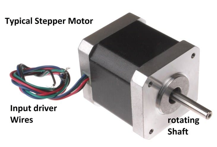
In this article I have explained how to drive a unipolar stepper motor using an integrated circuit (IC) such as the ULN2003 or the L293D.
The article gives a basic explanation of stepper motor operation and distinguishes between bipolar and unipolar stepper motors.
It then goes on to describe the basic circuit diagram for driving a unipolar stepper motor using an IC.
In this article I have explained the correct way to connect a stepper motor to an IC. It further explains how to configure the IC with a microcontroller to control the motor's speed and direction.
For anyone interested in learning how to utilise an IC to operate a unipolar stepper motor, the paper serves as a helpful resource. Readers may create their own stepper motor control circuit and use it to robotics, automation, and precise positioning by adhering to the instructions in the text.
Servo Motor Controller Circuit
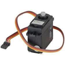
This article teaches you how to make a little machine called a servo motor move using a special type of electronic component called a 555 IC.
The article begins by explaining what a servo motor is and regarding its application. Then, it shows you how to connect the 555 IC to the servo motor using some wires and a breadboard (which is like a little tool that helps you connect electronic components together).
Next, the article explains how to program the 555 IC using a simple code that tells the servo motor how far to turn and in which direction.
Lastly, the article shows the right method of powering the circuit through a battery. It further explains how to test your servo motor and whether it is working correctly or not.
Overall, this article is a fun and easy introduction to electronics and programming. By following the steps provided in the article, you can make your very own servo motor move and control it using a simple electronic circuit.
Inverter Circuit
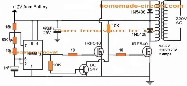
This article is about making a simple electronic circuit called an inverter using a special component called an IC 555.
You can use an inverter mainly to convert direct current to alternating current. This is advantageous as many appliances and electronics, such as lights and appliances, require AC to function.
In this article I have explained how to connect the IC 555 to some other electronic components, like resistors and capacitors, to make the inverter circuit. It also shows you how to connect the circuit to a battery so it can work.
Finally, the article explains how to test the circuit by connecting it to some devices that need AC, like a light bulb or a small fan.
By following the instructions provided in the article, you can make your very own 555 inverter circuit and power some AC devices such as lamps and fans.
Alternate Load Control Circuit
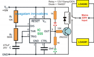
This article is about building a timer circuit that can control the switching of a relay.
The article starts by explaining how a relay works. A relay is an electrical switch that is controlled by an electronic circuit. It is useful for controlling high-power devices, like motors or lights, using a low-power electronic circuit.
The article then goes on to describe the timer circuit, which is based on the popular 555 timer IC. The circuit is designed to alternate the switching of two relays at a set time interval.
The article provides a detailed explanation of how the circuit works through a circuit diagram. It also provides suggestions for adjusting the time interval and using the circuit in different applications.
By following the instructions provided in the article, you can build your own timer circuit and control the switching of relays for various applications.
Stop Watch Circuit
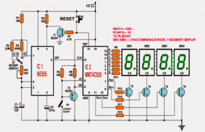
This article is about building a digital stopwatch circuit using electronic components like counters and display drivers.
A stopwatch is a device which can be used to determine the magnitude of time elapsed between the beginning and the finish of an event.
In this article, the stopwatch is made using electronic components rather than a physical device.
In this article I have explained how to build the circuit using a counter chip, display driver chip, and a few other electronic components. The circuit counts time in increments of one second and displays it on a digital display.
The article includes a circuit diagram and a detailed explanation of how the circuit works. It also provides suggestions for adjusting the time increments and using the circuit in different applications.
Set Reset Circuit
This article is about building a set-reset (SR) latch circuit using the popular 555 timer IC.
An SR latch is a type of electronic circuit that can store a single bit of information, like a memory cell. It can be used to control other circuits, like switches or motors, based on the stored bit of information.
In this article I have explained how to build the circuit using a 555 timer IC and a few other electronic components. The circuit includes two input pins, one for setting the latch and one for resetting it. The output pin of the circuit will switch to a high or low state depending on the input pins.
The article includes a circuit diagram and a detailed explanation of how the circuit works. It also provides suggestions for using the circuit in different applications.
Emergency Lamp Circuit
This article is about building a simple automatic emergency light circuit that can be useful during power outages.
A battery-operated light source known as an emergency light automatically activates in the event of a power interruption or other emergency. When the power source is cut off, this circuit is built to automatically switch on an LED light.
A transistor, a diode, a resistor, and an LED are some of the electronic parts that are used in the article to demonstrate how to make the circuit. A 9V battery supplies power to the circuit.
The article includes a circuit diagram and a detailed explanation of how the circuit works. It also provides suggestions for adjusting the circuit for different applications.
Low Battery Indicator Circuit
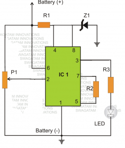
In this post, we'll go through how to create a straightforward low battery-level indicator circuit that can be used to monitor battery life.
A low battery indicator is a tool that alerts the user when a battery's voltage falls below a preset threshold.
This can be useful for preventing damage to electronic devices that rely on batteries for power.
In this article I have explained how to build the circuit using a few electronic components, including a transistor, a diode, a resistor, and an LED. The circuit is powered by a 9V battery and can be used to detect low battery voltage for any other electronic circuit.
The article includes a circuit diagram and a detailed explanation of how the circuit works. It also provides suggestions for adjusting the circuit for different battery voltages.
PWM Generator Circuit
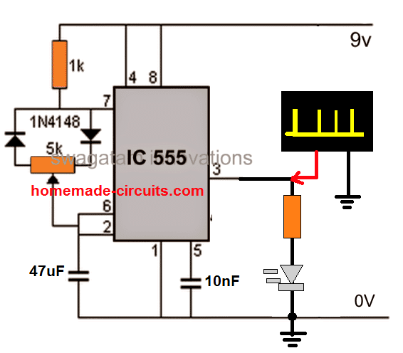
This article describes how to produce Pulse Width Modulation (PWM) signals using the common integrated circuit (IC) 555.
PWM is a technique used to control the speed of motors, dim lights, and regulate power.
The article provides a simple circuit diagram and detailed instructions on how to generate PWM signals using IC 555. It also explains the role of various components in the circuit and how to adjust the duty cycle of the PWM signal.
Overall, this article is a great resource for anyone interested in learning about PWM signals and how to generate them using IC 555.
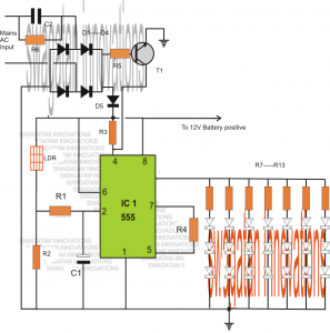
LED Flashing, Fading and Blinking Circuit
In this article I have explained how to make a simple circuit to create an interesting LED light show using the IC 555. Specifically, it shows how to build a circuit that can make LEDs flash and fade in an appealing way using this IC.
The circuit can be built using just a few basic components, such as 1) resistors, 2) capacitors, and 3) IC 555.
The article includes a thorough schematic design of the circuit as well as extensive guidelines for constructing and testing it. It also includes a breakdown of the necessary parts and links to online stores where you may buy them.
The author of the article explains how the IC 555 circuit works, noting that the flashing and fading effect is achieved by varying the voltage across the LEDs. They also suggest some modifications that can be made to the circuit to alter the timing and speed of the flashing and fading.
Overall, the article provides a clear and concise guide for creating a simple LED light show circuit. It is suitable for beginners with some basic knowledge of electronics, and it offers opportunities for experimentation and customization.
Capacitance Meter Circuit
IC 555 capacitance meter is a simple and low-cost device that uses the versatile 555 timer IC as the core component to measure the capacitance of an unknown capacitor.
The device works by using the 555 timer IC in astable mode to generate a square wave signal, which is then fed into the unknown capacitor.
Measurement of the capacitor's charging and discharging times allows for the calculation of the unknown capacitor's capacitance value using resistance and voltage values that are already known.
The IC 555 capacitance meter is a handy tool for hobbyists and students who need to measure capacitance quickly and easily, without the need for expensive equipment.
Rat Repellent Circuit
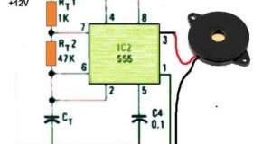
The IC 555 rat repellent circuit works by emitting a high-pitched sound that is unpleasant to rats and mice but is inaudible to humans and most other animals.
By adjusting the circuit's resistor and capacitor values, the frequency of the sound may be changed to make it more effective against various rodent species.
The circuit is simple and easy to build, even for beginners in electronics.
An IC 555 timer, a few capacitors and resistors, a speaker or buzzer, and a power supply are all that are required.
A 9V battery or a DC power source could be used to operate the circuit.
To build the circuit, start by connecting the IC 555 timer to the power supply and the ground. Then, connect a capacitor and a resistor in series between the power supply and the trigger pin of the IC.
Next, connect another capacitor and a resistor in series between the power supply and the threshold pin of the IC. Finally, connect a speaker or buzzer between the output pin of the IC and the ground.
Dog Whistle Circuit
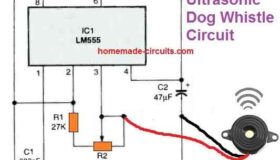
A dog whistle circuit based on an IC 555 is a simple and effective approach to generate a high-pitched sound that dogs can hear but humans cannot.
The circuit uses the versatile 555 timer IC to generate a square wave signal at a frequency of around 20 kHz, which is within the range of hearing for most dogs.
The construction of this circuit is pretty simple, requiring only a few capacitors, resistors, and a speaker.
The circuit requires 9V PP3 battery to operate
The circuit can be used to train dogs, call them, or simply to test their hearing.
In contrast to conventional dog whistles, which may be damaging to dogs and other animals, it is a secure and compassionate substitute.
Not satisfied with the above IC 555 circuits and projects? No worries, please feel free to comment which IC 555 project have I missed in the above article, I will make sure to update it ASAP.
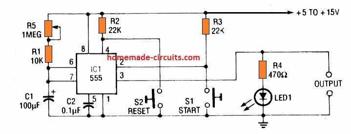
Porch Light Circuit
The diagram below illustrates the configuration of an automatic IC 555 porch light control system using relay outputs.
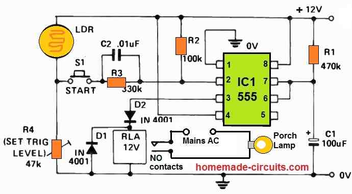
This system activates the porch lights for a predetermined 50-second duration exclusively during nighttime or when dark conditions are detected.
The circuit's triggering mechanism relies on switch S1, which can take the form of either a microswitch activated by a porch gate or a pressure-pad switch activated by body weight and hidden beneath a porch mat or rug.
The circuit's operation hinges on the requirement that the negative-going trigger pulse, which is supplied to pin 2 of the IC (Integrated Circuit), must fall below the internally regulated '1/3 Vcc' voltage level of the 555 timer for proper timing cycle initiation. If the trigger pulse fails to drop below this threshold, the trigger signal cannot initiate timing cycles.
In this design, a light-dependent resistor (LDR) and preset resistor R4 are connected in series to form a light-dependent potential divider.
One side of switch S1 is connected to the output of this potential divider, while the other side of the switch is linked to pin 2 of the IC through the C2-R3 combination.
When exposed to bright or daylight conditions, the LDR exhibits low resistance, resulting in a high voltage at the potential divider's output.
As a result, closing switch S1 generates a voltage pulse much higher than '1/3 Vcc,' preventing the timer from being triggered in 'daylight' conditions.
Conversely, the LDR exhibits high resistance in dark or 'night' conditions, leading to a low voltage at the potential divider's output.
In this scenario, closing switch S1 generates a voltage pulse significantly lower than '1/3 Vcc,' causing the timer circuit to be triggered via S1 under 'night' conditions.
Practically speaking, the LDR can be any cadmium-sulphide photocell with resistance falling within the range of 1 kΩ to 100 kΩ under the required minimum 'dark' turn-on condition. R4 can be adjusted to preset the minimum 'dark' level at which the circuit initiates.
It's important to note that the trigger signal is routed to pin 2 of the IC through the C2-R3 combination, which serves as a trigger signal conditioning network, effectively isolating the DC component of the LDR-R4 potential divider from the 555 IC's trigger pin.
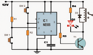
Car Lights ON Warning Alarm
In this setup, a 555 alarm circuit is employed in a slightly unconventional triggered oscillator configuration, serving the purpose of indicating whether your vehicle's lights have been inadvertently left on when you exit the car.
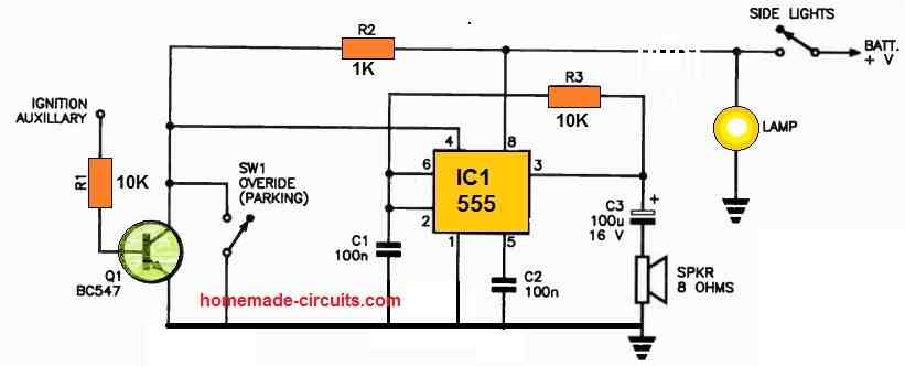
Upon turning off your car's ignition, the auxiliary circuit connected to the ignition switch activates, supplying a voltage of 12 V.
This voltage is utilized to bias Q1, causing it to pull pin 4 (the reset pin) of the 555 timer low.
If your lights have been accidentally left on, the side lights circuit remains powered, maintaining the electrical supply to the circuit.
This prompts the 555 timer to promptly initiate oscillation, and an integrated speaker produces an audible alert to notify you of the lights being left on.
The same outcome occurs if only the side lights are unintentionally left activated.
For enhanced safety measures, it is advisable to wire the parking lights switch in parallel with the collector of Q1.
Signal Injector
The 555 timer serves as an excellent tool for signal injection when troubleshooting audio and radio circuits.
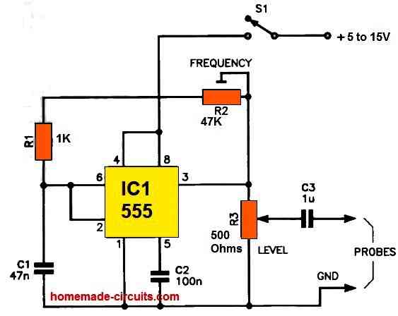
By connecting pins 2, 6, and 7 together and linking them to the R-C timing circuit comprised of RV1, R1, and C1, the 555 generates extremely brief and rapid pulses that extend harmonics well into the megahertz (MHz) range.
The primary oscillation frequency can be adjusted by manipulating RV1, while the output level can be controlled using potentiometer RV2.
Power for the circuit can be drawn either from the tested circuit itself, obtaining a voltage in the range of 5 to 15 volts, or from a 6-volt or 9-volt battery source.
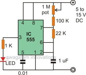
Voltage Controlled Oscillator
Presented below is an elegantly simple voltage-controlled oscillator (VCO) circuit employing the 555 IC. VCOs find wide-ranging applications due to their versatility. This particular circuit offers an extensive frequency range, exceeding a 100:1 ratio.
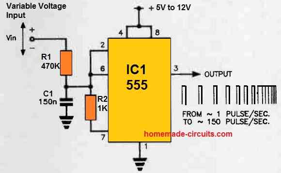
Rather than connecting the timing capacitor to the positive supply rail, it is linked to a variable voltage source.
This action alters the trigger and threshold voltages, thereby modifying the time it takes for the capacitor to charge, resulting in changes in the oscillator's frequency.
This circuit excels in achieving a high degree of linearity in converting voltage variations into frequency shifts.
It also provides a broad frequency range spanning multiple decades.
Using the specified component values, the output frequency can be adjusted from approximately one pulse per second to around 150 pulses per second by varying the input voltage across a range of several volts.
If the output pulse width is not a crucial consideration, you have the option to remove the 1K resistor connected from pins 2 and 6 to pin 7, which serves to elongate the output pulse.
Two LED Flasher Circuit
Due to the 555's output circuit configuration, which resembles a transistor totem pole, it possesses the capability to both source and sink current.
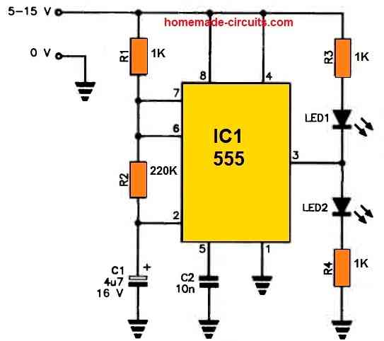
Consequently, it can be configured to activate LED1 when in the low state and LED2 when in the high state.
In this particular two 555 flasher setup, it's configured to generate a slow flashing effect, following the traditional astable configuration, with the timing controlled by the values of R1, R2, and C1.
R3 and R4 serve the purpose of restricting the current flowing through LED1 and LED2, respectively.
How to Connect a Relay with IC 555 Correctly
The following diagram shows how you can drive a relay from the 555 correctly.
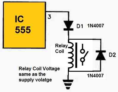
The 555's output off voltage, which normally might never bcome zero, is neutralized by diode 1.
Whenever the coil current is switched off, Diode D2 eliminates the relay's back-emf.
It should be noted that the relay coil current specifications must not exceed the 555's 200 mA output current rating.
Diode D1 needs to be appropriately rated to withstand the relay coil current.
You may use a standard 1 A rectifier diode [1N4002, 1N4007, etc.]. D2 might be either a 1N914, 1N4002, or 1N4007.
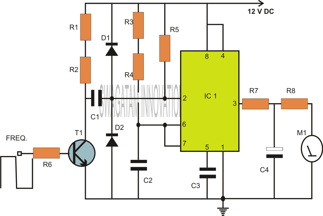
Adjustable PWM Circuit
The IC 555 timer's threshold pin (pin 6) and discharge pin (pin 7) play an important role in regulating the charge and discharge operations of the external RC timing circuit connected to IC1.
In this configuration, the indicated diodes create a separation between the paths for charging and discharging.
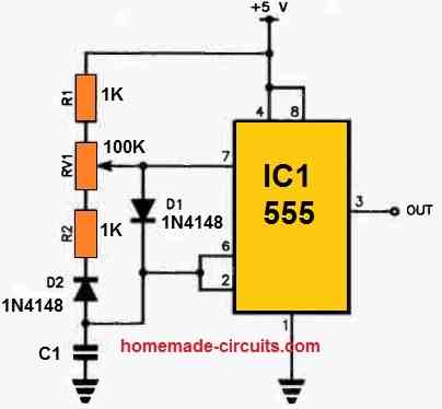
During the period when the capacitor is being charged, D1 effectively bypasses a portion of RV1 and R2, leaving only the resistance of R1 and a portion of RV1 to control the time required for the capacitor to charge up to 2/3 of the supply rail voltage.
During the discharge period of the cycle, the capacitor discharges via D2 and R2, in conjunction with the specific adjusted portion of RV1. The resistance offered by this adjustment decides the duration needed for the capacitor to discharge to 1/3 of the supply rail voltage.
By adjusting RV1, it becomes possible to modify the charge and discharge ratios, thus determining the desired the output's mark-to-space ratio.
How to Connect a Loudspeaker with IC 555 Correctly
If you are wondering how to correctly configure a speaker with IC 555 output (pin#3), the following explanation shows eight methods for connecting a loudspeaker to the 555 time/oscillator:
The first circuit shown below is straightforward.
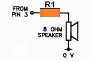
The resistor is included to restrict the 555's output current to the speaker. Its value can vary, ranging from 22 Ohms for lower voltage supplies (5-7 V) to 120 Ohms for supplies up to 15 V.
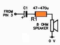
For a more pleasing audio quality, consider the second circuit shown below, which incorporates a capacitor in series, ranging from 47u to 470u.
The third and the fourth below designs offer increased volume from the speaker by utilizing either an NPN or a PNP transistor current amplifier, respectively.
If you desire even greater volume, the following fifth and sixth circuit configurations are ideal choices.
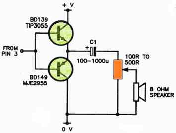
The PNP configuration above shows how the resistor can be substituted with a potentiometer for volume control, while C1 can have a value between 10u and 470u.
To achieve exceptionally loud output, opt for the below shown 7th circuit design. This design employs a pair of complementary transistors in totem pole configuration to drive the loudspeaker to its limits. The potentiometer allows for fine-tuning the volume if necessary.
For driving a speaker with the CMOS version of the 555 (7555, TL555CP), you can try the 8th design as shown below.
This setup employs a Darlington transistor switch, where R1's value can range from 10 to 150 Ohms, depending on the power supply voltage and desired output volume.
Advantages of IC 555
- The integrated circuit 555, or NE555, presents a multiplicity of advantageous features, including its capacity to generate precise and stable time delays with exceptional accuracy and reliability.
- The device boasts low power consumption and high output current, rendering it a desirable choice for low-power and low-voltage applications.
- Its flexible operating modes, such as monostable, astable, and bistable modes, endow it with the ability to perform a diverse range of functions and operations.
- The IC 555's straightforward design and configuration make it facile to use and integrate into various electronic circuits.
- Its operational requirements are minimal, and the device exhibits a broad supply voltage range, facilitating its utilization across diverse environments and conditions.
- Exceptional temperature stability and tolerance render the IC 555 a dependable option for operation in varying temperatures and environmental conditions.
- The device's low distortion and noise profile make it particularly well-suited for applications necessitating high accuracy and precision.
Conclusion
The IC 555 timer, which may be utilised in a number of electrical circuits and applications, is a highly adaptable and extensively used integrated circuit.
There are countless possibilities for DIY enthusiasts and students to experiment with, ranging from straightforward timer circuits to more complicated ones like PWM circuits and tone generators.
Detailed circuit diagrams, tutorials, and explanations were included in this post together with a complete collection of well-liked IC 555 circuits and projects.
Our goal in writing this post was to give readers useful insights into the world of IC 555 circuits and projects and to motivate them to start new electrical projects.
The IC 555 timer will surely remain a significant component in the field of electronics as technology develops, and we anticipate discovering fresh and creative uses for this versatile chip in the future.

Questions & Answers
Good day sir. this design gives different voltages at the two drains with respect to +12v. what could be done or is it okay that way?
Hillary, which circuit are you referring to? please post under the same article…
Thank you so much!