This simple signal injector circuits I have explained below can be accurately used for troubleshooting and alignment applications of all kinds of audio and high frequency equipment.
1) Using a Single IC 7400
One of the extremely handy devices for repairing audio and high frequency instruments is without question a equipment that will give you a modulated frequency to allow tracing the path of the signal via the circuit.
This single IC signal injector circuit employs probably the most prevalent TTL integrated circuits, the SN7400N, which is made of four 2-input NAND gates. Although the overall circuit part number is 40, just about five of these are inside the i.c. package which ensures that building becomes super easy.
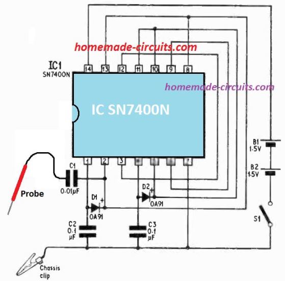
How it Works
By correctly joining the four gates of the IC as shown above, configures a multivibrator square wave generator having a fundamental frequency within the full audio range.
Due to the fact that the the output waveform from this circuit produces extremely short ON/OFF periods, the harmonics generated range in the high frequency UHF band.
Therefore the generator could be used to for troubleshooting all types audio equipment along with VHF, UHF receiver circuits.
How to Test
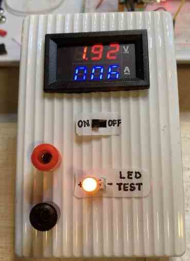
The completed device could be tested by attaching a pair of headphones between the probe terminal and chassis negative clip of the circuit. If everything is good a frequency note of approximately 3kHz will be clearly audible.
To test the ultra high frequency (UHF) attributes of the generated tone, hook up the probe to a TV receiver aerial socket, and switch ON power. You must now be able to hear an audible output from the TV receiver speakers.
The earth clip is actually not necessary for use when the injector is used at radio frequencies, however you may find a much amplified output if it is clipped with the negative of the circuit under test.
Parts list for the above design is given below:
2) Using IC 4011
This signal injector design provides an output consisting of a 100 kHz fundamental frequency and harmonics ranging as high as 200 MHz. The circuit also comes with an output impedance of 50 ohms.
The NAND gates N1, N2 and N3 work like an astable multivibrator with a perfectly balanced squarewave output and a frequency that's roughly 100 kHz. The fourth NAND N4 gate is employed as a buffer stage at the oscillator output.
Because we have a perfectly symmetrical squarewave at the output, it includes only the odd harmonics of the fundamental frequency, wherein the harmonics in the higher order tend to be rather weak.
This is because of the relatively slow rise time of the CMOS ICs used in this circuit.
How the circuit Works
Since it is important for the upper harmonics to be abundantly present, to ensure that the circuit works efficiently at high frequencies, the N4 output can be seen connected to a differentiating network R2/C2.
This network attenuates the fundamental frequency with respect to the harmonics, generating a sharply pointed pulse waveform.
This waveform is then amplified by T1 and T2. This signal includes a high amount of harmonics and, because the waveform has extremely low dutycycle, this stage along with T2 consumes hardly any powerparticularly.
The output frequency from the signal injector circuit could be tweaked through the preset P1.
When a precise output frequency becomes necessary then the signal injector could be fine-tuned by eliminating its 2nd harmonic with the 200 kHz Droitwich broadcast transmitter.
The frequency stability of the signal injector depends on how technically well it is constructed.
To reduce capacitance effects from the user's hand, the device must be encased inside a metallic box which will work like a shielded cover, with only one terminating output in the form of the testing probe.
In case preferred, a 1 k preset could be incorporated in series with P1 to enabling more granular fine-tuning.

Parts List
All resistors are 1/4 watt 5%
- R1 = 47k
- R2 = 27k
- R3 = 100k
- R4 = 470 ohms
- R5 = 15k
- R6 = 47 ohms
- P1 = 50k preset
- C1, C3, C4 = 100pF
- C2 = 10pF
- C5 = 1nF
- T1, T2 = BC547
- N1--N4 = IC 4011
- battery = 9V PP3
3) Another IC 4011 Injector
Many of the on-market low priced signal injectors generate a squarewave output of around 1 kHz.
Although the squarewave is abundant in harmonics that span out into the Megahertz range, these are helpful to test r.f. Circuits, and the basic need for audio processing.
The signal generator discussed here is subtly different seeing as how the 1 kHz squarewave is switched on and off at roughly 0.2 Hz, making the troubleshooting procedure much easier.
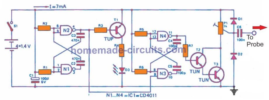
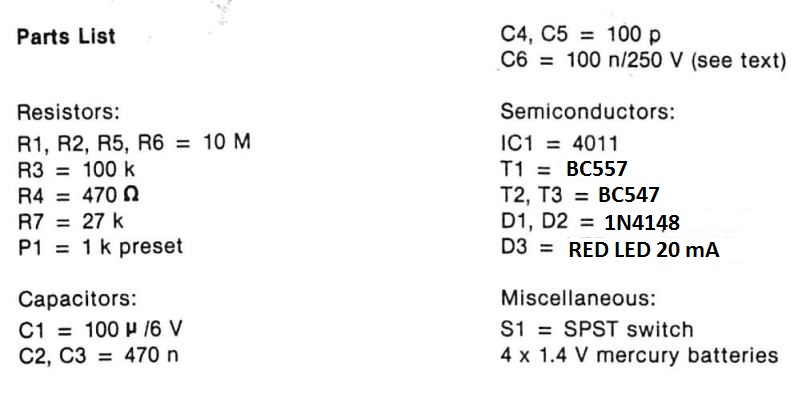
Figure 1 displays the entire signal injecter circuit. The tracking oscillator is an astable multivibrator constructed across a couple of CMOS NAND gates N1 and N2.
It therefore switches T1 on and off, driving an LED indicating if the signal is on.
Circuit Description
The 1 kHz squarewave generator also includes an astable multivibrator that uses the two additional NAND gates in the IC 4011 pack .
The astable is gated on and off by the 1st astable. The 1 kHz oscillator output is buffered by the T2 and T3 transistors, the output being extracted from the T3 collector through a potentiometer P1 that is used to tweak the output level.
The peak voltage at the output is equal to the supply voltage (5.6 V). Diodes D1 and D2 enable some protection from harmful transients for T2 and T3, and C6 inhibits the circuit of any DC voltage on the circuit which is being tested.
High Voltage Application
In particular, if the signal injector is to be used to troubleshoot high voltage circuits, then C6 operating voltage has to be rated at 1000 V.
In this case it would be too bulky to install directly on the PCB, as given in the following layout .
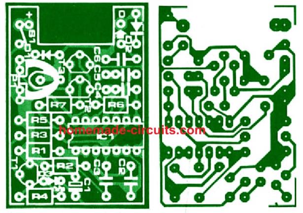
Mounting the entire circuit inside a well insulated box is also a smart option, particularly when operating on AC LIVE audio equipment.
The specs of D1 and D2 should be able to withstand whatever intermittent voltages and currents that may likely occur.
Four 1.4 V mercury batteries power for the circuit. The specific battery technology chosen becomes an user preference.
4) Using an UJT
This straightforward signal injector circuit, based on a UJT (Unijunction Transistor), serves as a valuable tool for testing audio amplifiers, medium and shortwave receivers.
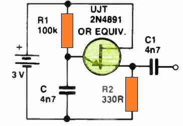
It can even generate horizontal bars on a TV set when connected to the antenna terminals.
Upon power-up, capacitor C starts charging through resistor R1 until the UJT reaches forward biasing.
Subsequently, the UJT provides a discharge path for C via its emitter and resistor R2, causing C to discharge rapidly until the transistor is no longer forward-biased.
When this state is reached, capacitor C begins charging once more through R1, completing a single cycle of oscillation.
The swift discharge of the capacitor through the UJT results in a sharp pulse rich in harmonics, which can be conveniently output through a decoupling capacitor C1 to the probe tip.
For a stronger signal, you can ground the signal injector to the system under test using an alligator clip.
Signal Tracer and Signal Injector Circuit
This exceedingly simple circuit may be used as a diagnostic tool for audio and AM radio circuit problems.
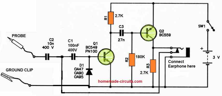
When a high impedance earphone is attached to the jack socket, the circuit starts working like a signal tracer.
Any input RF signals are corrected by D1 by connecting the clip to the circuit ground and examining the signal source with the probe. Q1 and Q2 then amplify the generated sounds.
The circuit starts working like a signal injector oscillator when the earpiece is disconnected, with the output being injected through the probe.
For C1 and C2, it is advised to use 400 V greencaps to ensure safety.
In addition, the circuit uses little power, thus even if SW1 is left closed, the battery may survive a long time. It's feasible to utilize a 1.5 V AAA cell for operating this signal tracer circuit.
Questions & Answers
Hi,
I build guitar pedals from kits,powered with 9V or 18V, and I’m looking for a signal injector to identify connection problems.
Could you recommend one of those listed above?
Thank you
Patrick
Hi, You can use any of the above injector concepts for troubleshooting your circuit, all are designed to do one basic function of producing a high pitched frequency which can be tracked within your circuit to trace the faults.
The UJT based design is the simplest one, so you can try that.
Thank you for your reply
You are welcome!
A 4k7 capacitor in parallel with R7 2k7 will improve a lot high frequency output.
As farmer i face underground power cable fault in my farm and many more farmer face that kinda problem too…n as electronics hobbiest i know how to use this device but i need this device as wireless detector…like as metal detector so I can find my broken underground cable i am able to inject signal from one end of cable n i want to detect it pinpoint at broken place wirelessly..coz most cable buried 3 to 4 feet underground…will yahelp me to clear my concept ??? Most farmer who has underground cable face this kinda problem…so please help me bro…
Yes, I can understand the issue faced by the farmers.
Would it be possible to feed a 220V Ac from one end of the cable?….Then it could be very easy to trace the cable and locate the breakage using the following circuit:
Non Contact AC Phase Detector Circuit [Tested]
Yup it’s very possible to in anythung at both end (mains 3phase supply end or 3phase submersible motor end) we can inject rf or af signal at both individual core end.bt rest of wire is always underground upto3 to 6 feet..and in this field i need to find broken wire wirelessly…n thanks for kind reply…
OK great, then the above linked circuit can be used. You can also try the following concept:
Anti Spy RF Detector Circuit – Wireless Bug Detector
Thanks for kind reply n reference …let me try n reply later..
Sure, no problem…
hello
i would like to make a probe for a used signal tracer i bought off eBay.
do you have a article on how to make such a probe?
i would use what i have around the house,like old coax cable, maybe a old multimeter probe.
thanks
john
Hi, can you provide the specifications of the probe?
yes you can easily use any multimeter probe…