The 16 fundamental IC 741 based op amp circuits presented here are not only interesting but also very amusing to build.
The included circuit ideas like inverting and non-inverting amplifiers, tone control and regulated power supply will surely intrigue you. Circuit diagrams are also attached with the article.
Application Circuits (Learn More)
We all are probably aware regarding the high versatility of the IC 741.
Amazingly an infinite number of 741 opamp circuit design ideas can be wired by adding just a few passive components to it. We investigate a few of these projects here.
IC 741 is one of the most versatile and multipurpose op-amp and can be wired up in numerous different ways.
Let’s study some of the important 741 opamp applications circuits, as I have explained below:
1) Inverting DC Amplifier:
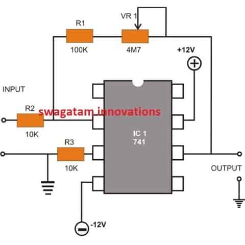
Sometimes it becomes important for amplifying DC voltages, the diagram above shows how the IC can be wired up into an inverting DC amplifier circuit.
As the name informs a DC input to the IC will be amplified at its output but will be just the opposite with polarity. VR1 may be used for adjusting the gain of the amplifier.
2) Non-inverting DC Amplifier:
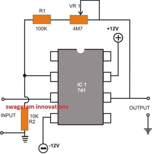
This configuration is similar to the above circuit, the only difference being the output response, which is always equal to the polarity of the fed input voltage.
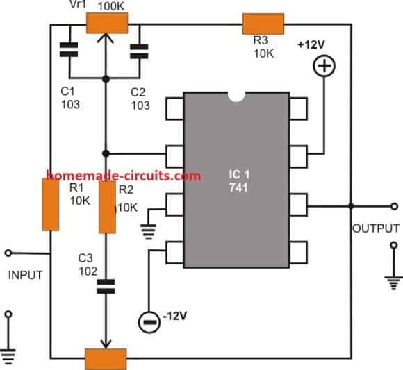
3) Inverting AC Amplifier:
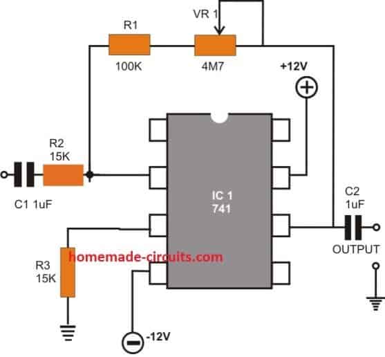
The figure shows how the basic inverting DC mode of the IC can be simply modified into an inverting AC amplifier design.
This circuit is intended to be used with AC or oscillating input signals, primarily for amplifying minute frequencies. C1 and C2 form the input and the output coupling capacitors.
Again here the gain may be varied using the pot VR1.
4) Non-Inverting AC Amplifier:
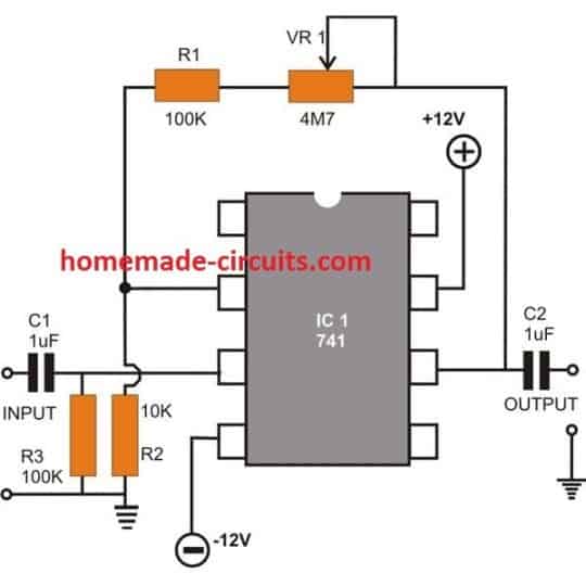
The 741 op amp circuit is similar to the above explained design; the only difference being the output of the circuit provides oscillations in phase with the input whereas the previous design produces oscillations with opposite phase to that of the input.
5) Active Tone Control:
The opamp IC741 can be very effectively used for processing audio frequencies and customizing them as per one’s own choice.
Folks who prefer more bass in music may achieve it by just adjusting the bass control shaft whereas those who appreciate extra treble with music may do the same through another similar control reserved for the purpose.
The circuit diagram shows how by adding just a few passive components with the IC 741 a neat little active tone control circuit can be built.
For the given values, the circuit provides a bass boost of 12.5 dB and a cut of 10.5 dB at around 100 Hz.
The treble chill is of 8.8 dB with a cut of 9.8 dB at around 10 kHz, with respect to the set gain of the device at 1 kHz. The circuit also features high input impedance and low output impedance.
6) Stabilized Power Supply Circuit Using opamp IC 741
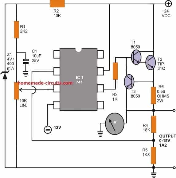
The final diagram of this article shows a classic stabilized voltage DC power supply using 741 opamp circuit design.
A cheap zener / resistor voltage reference is used to provide a reasonably stable reference to the non-inverting input of the IC.
The pot VR 1 is used to set the output voltage right from zero to a maximum of 15 volts continuously. A Darlington pair transistor is used at the output to enhance high current delivering capacity.
However another transistor T3 has also been incorporated to check the above current if it tends to drift beyond limit.
The control limit may be set by varying the value of the resistor R6.
7) Power Amplifier Circuit using IC 741
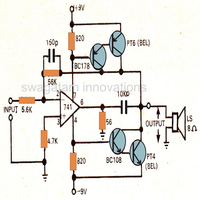
Though the maximum power of this amplifier is not more than 4 watts, the amplifier provides relatively good response with the applied frequency.
The distortion of less than 0.5% and has a bandwidth of over 20kHz. The amplifier requires a minimum input of around 150 mV.
8) IC 741 Darkness Controller Relay
The darkness activated relay can be used to automatically switch on a doorstep or veranda light, automatically switch on a night lamp inside a kid's bedroom, the application can be countless.
What goes on, basically, is that as soon as night fall strikes the LDR, the relay is activated. If you would like the relay to run a low voltage gadget, go with a relay having low voltage contacts.
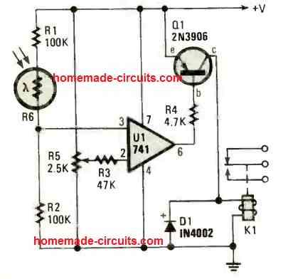
If you would like it to use anything more substantial, select a relay having contacts that can handle the voltage (and current) equivalent to the load wattage.
It's exactly that easy. Just be sure the relay coil is rated not less than 150 ohms. With standard brightness, the R6 LDR's resistance will be low.
The input potential at pin 3 of IC U1 will be high, which will cause a high at the output at pin 6.
Since the transistor Q1 is a PNP transistor, and the collector current will be reduced as long as the pin6 of the IC 741 holds it base positive.
As soon as light source to the LDR becomes low or when darkness sets in, the R6 LDR resistance increases.
In this situation Pin 3 of the IC 741 turns in a negative course, causing the output of IC 741 at pin 6 to become low or around zero voltage.
This situation resources the required negative base current to Q1 base via the 4k7 resistor, R4. Collector current of the transistor now increases, and the relay gets instantly activated. When the relay gets activated, the connected lamp or any load turns ON.
9) 741 Touch Switch Circuit
This IC 741 touch switch circuit a sensitive touch-operated switch, which could also be applied (if you like) like a rain detector.
As shown in the figure Pin 3 of the IC 741 is fixed by resistors R1 and R2. Inverting input (pin 2) is taken to the slider arm of the preset R3, that enables you to set the activation limit.
As soon as you put your finger on the touch plate, it bridges the odd and even copper stripes of the touch plate, which causes pin 2 to turn negative, which amplifies the effect, causing pin 6 of the IC 741 to become positive.
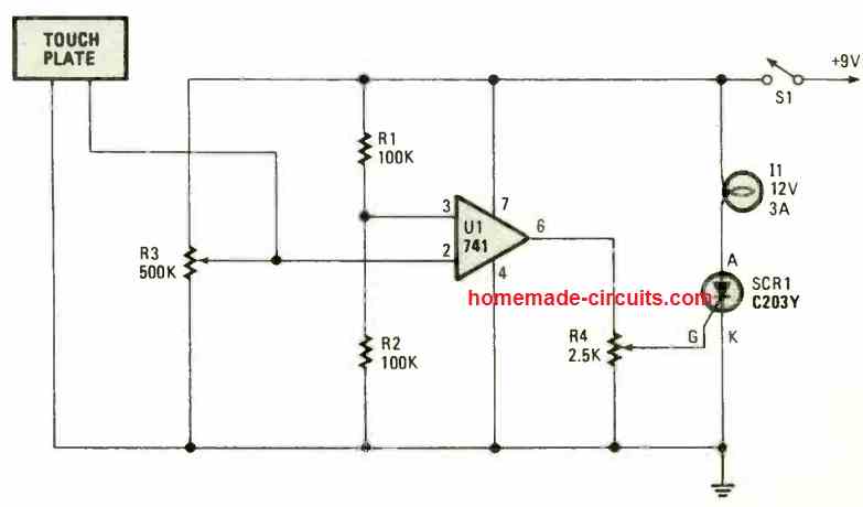
In the normal situation the SCR remains in the switched OFF condition, keeping the lamp shut off.
When pin6 turns positive due to touching of the touch plate, causes the SCR gate go positive, and the SCR fires and conducts and gets latched, switching ON the lamp, which is kept switched ON until the power supply to the circuit is turned OFF by S1.
10) Proximity Sensors using IC 741
The proximity sensor displayed below exploits the noise generated by the 50 or 60 Hz AC junk that surrounds us. The main operational element in this circuit is a 741 op-amp IC.
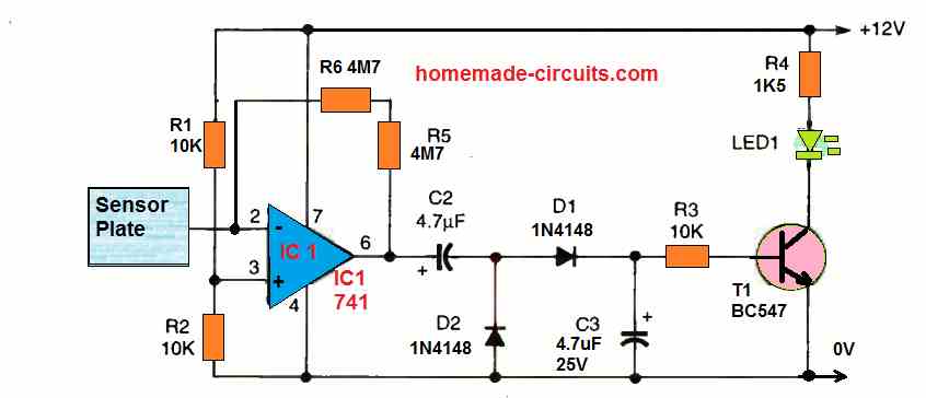
Through a couple of 4M7 feedback resistors hooked up between the negative input at pin 2 and the amp's output at pin 6, the amplifier's gain is adjusted to almost maximum.
The metallic pick-up sensor is wired to the input at pin 2 and should be placed extremely near to the IC circuitry.
The output of the amp is sent into a detector/rectifier circuit, which delivers a positive driving voltage to the base of the BC547 NPN transistor.
When an item is sensed, the transistor turns on the LED. This sort of noise pick-up circuit requires a sensor no bigger than a half-dollar coin.
Ambient noise might create false triggering if somehow the sensor plate is too big. Simply touch your finger on or near the detector plate to activate it.
However, if you try to use this circuit in a location where there is no mains AC power around, it would probably stop working properly.
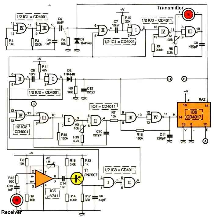
11) Proximity Sensor that does not Depend on Mains 50 Hz Hum
The identical 741 op-amp can also be used in a circuit which does not depend on an external signal source (AC mains hum).
The 741 op-amp is used in a high-frequency oscillator circuit that operates around its peak frequency in this very unique proximity sensor device described below.
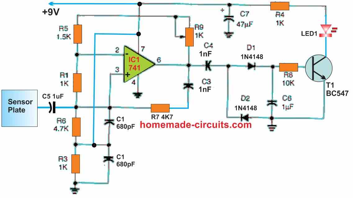
The internal feedback capacitor of the 741 op-amp restricts its peak frequency.
As the frequency increases, the gain of the op-amp lowers until it is just little larger than one. When we increase the frequency to that level, the feedback channel turns extremely load sensitive, which is exactly what is required in any load-type proximity sensor circuit.
The frequency-determining elements of the oscillator are C1, C3, R6, and R7.
The gain is determined by the feedback resistors R5 and R9. With R2 and R3, the bias of the op-amp is tuned to create a DC output on pin 6 at one-half the supply voltage, which has the benefit of being independent of any specific supply voltage.
We may leverage the greatest allowable output-voltage swing by operating the output at one-half supply. Voltages ranging from 9 to 16 volts will suffice.
The output of the oscillator at pin 6 feeds the rectifier circuit, which is composed of D1, D2, C4, and C6.
The positive output of the rectifier activates Q1 and illuminates the LED. R9 should be set to the position where the LED just starts to illuminate for optimal sensitivity.
At a range of two to three inches, a 4- by 6-inch metal sensor sheet, shielded from surrounding objects, can readily detect your hand proximity.
Larger plates can sense larger items from further away. The greatest surface area that permits circuit oscillation depends on the size of the sensor plate.
Too big or too close to a ground mass might prevent the circuit from oscillating. The negative supply of the sensor must be wired to ground or a big metal item that can create capacitance with the ground.
12) Dual Power Supply
A technique of getting dual balanced supplies can be to employ a supply splitter which provides a low impedance center tap with a single supply, instead of creating a couple of identical supplies and hooking them up in series.
A supply splitter like the one demonstrated in the circuit diagram is designed to be used and powered with an existing bench power supply.
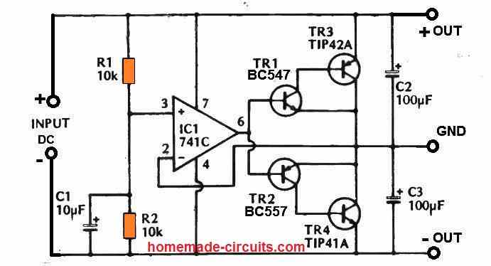
This specific circuit works effectively with supply voltages between 15V and 30V, with each of the output supply lines having a voltage corresponding to one half the input voltage (therefore, for instance 30V will be necessary at the input to provide +/-15V outputs).
The device can conveniently deal with currents of up to 100mA, and it may not be important to mount Tr3 and Tr4 transistors on heatsinks.
The dual power supply circuit is actually simply an unity gain amplifier consisting of a high input impedance and a low output impedance class B output stage.
A class B output stage is applied because it allows the circuit to have a low quiescent current usage (no more than 2mA). Tr1 and Tr3 are common emitter amplifiers.
However since there exists 100% negative feedback through Tr3's collector to Tr1's emitter, they provide not more than a unit gain. Tr2 and Tr4 are configured like a complementary output pair with Tr1 and Tr3.
13) Notch Filter Circuit
Occasionally, when dealing with analog signals, an incessant tone can be quite bothersome.
In such cases, an active filter comes to the rescue by effectively eliminating this unwanted tone, a process commonly referred to as "notching."
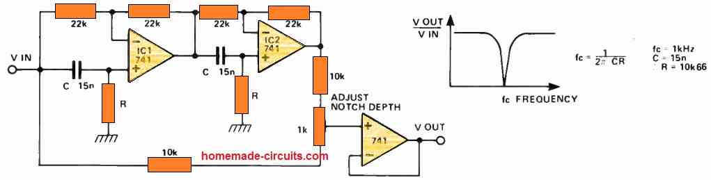
This IC 741 op amp based active filter can be finely tuned to precisely match the frequency of the undesired signal, allowing for its selective attenuation.
This technique is frequently employed to eliminate the presence of mains hum, for instance.
Here's how the circuit functions:
IC1 and IC2 constitute a pair of all-pass filters. These filters exhibit a flat frequency response, but their phase shifts in relation to frequency.
The most significant phase shift they can achieve is 360°, with a 180° phase shift occurring at a frequency of 1/2CR Hz. At this particular frequency, the signals undergo inversion.
Consequently, by combining the phase-delayed signal with the original signal, it's possible to achieve cancellation, thereby creating a distinct notch in the frequency response.
To obtain the most profound notch possible, the preset is utilized. Furthermore, the operational frequency can be modified by adjusting the two resistors, R.
For instance, if one intends to operate at 50 Hz, R should be set to approximately 220 kΩ.
14) Noise Generator
The phenomenon of zener breakdown in a transistor junction serves as a valuable noise generation element within various circuit applications.
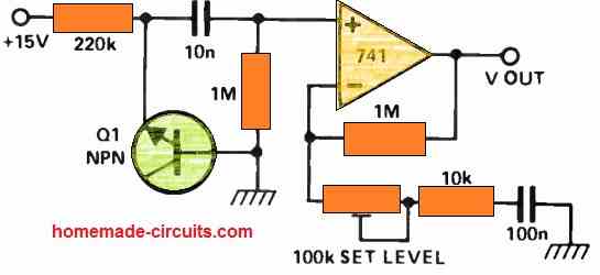
This breakdown process occurs spontaneously and results in the production of a low-level, inherently unpredictable noise voltage. Additionally, this noise voltage possesses a high source impedance.
To harness this noise effectively, an IC 741 operational amplifier is employed as a component with both high input impedance and substantial AC gain.
This configuration enables the creation of a noise source that exhibits low impedance while producing significant noise signals.
To fine-tune the noise level, an adjustable preset is utilized, allowing for the manipulation of gain across a range from 20 to 40 decibels.
15) Telephone Amplifier Circuit
This particular IC 741 based audio amplifier is designed to deliver speaker-level volume from your telephone without the need for any physical connection to the phone itself.
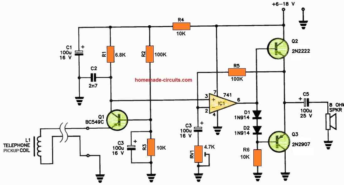
To set up this system, you'll need a telephone pickup coil, which can be easily obtained from electronics retailers. This coil is typically affixed either behind the earpiece on the handset or beneath the phone, near the line hybrid transformer.
The coil, denoted as L1, captures signals induced by the telephone's audio output. These signals are then amplified by Q1, operating as a common-base amplifier.
The collector of Q1 is directly linked to the non-inverting input of IC1. The output of IC1, in turn, is responsible for driving the base inputs of the complementary transistor output stage, consisting of Q2 and Q3.
This clever arrangement allows for efficient amplification of the telephone's audio output without requiring a physical connection to the phone itself.
Feedback is established through the resistor R5, while the amplification level is finely tuned using RV1. R2-R3 play the role of providing the necessary bias for Q1.
C3 serves as an AC bypass for the base of Q1, ensuring the proper signal path. Meanwhile, C2 contributes to high-frequency roll-off, effectively reducing unwanted extraneous signals.
In the circuit, D1 and D2 fulfill the vital function of creating base bias separation for the output stage devices, which operate in class B configuration.
This versatile unit can be powered by a DC supply within the range of 6 to 18 volts. It delivers an impressive power output of approximately 1 to 1.5 watts.
While selecting a speaker, it's essential to consider that larger speakers tend to be more efficient than their smaller counterparts, ensuring optimal audio performance.
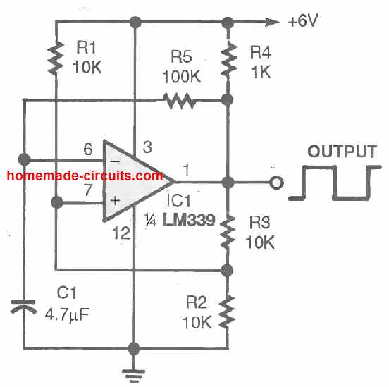
16) Switching ON/OFF Timer Circuit using IC 741
This circuit serves as an excellent solution for creating an automatic ON/OFF repeating timer suitable for applications like displays or slide-show presentations.
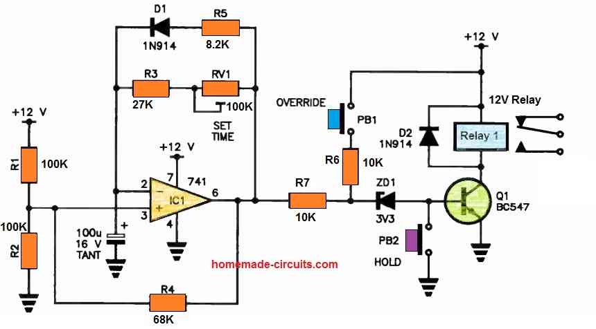
IC1, represented by the IC 741, functions as a square wave oscillator with an extended cycle period, featuring a low mark-to-space ratio thanks to the diode incorporated into the feedback network.
To enable IC1's output to oscillate between near-ground and close to the positive voltage rail, its non-inverting input is biased to approximately half of the supply voltage.
When IC1's output goes high, it activates Q1, subsequently engaging the relay.
The duration between these pulses can be adjusted within a range of approximately five to 30 seconds or thereabouts, a setting determined by RV1. The duration for which the relay remains active is determined by R5.
The circuit offers an Override button and a Hold button for added functionality.
The Override button allows you to trigger the relay manually in between the automatic pulses; it only requires momentary operation, or you can employ a momentary-action pushbutton.
On the other hand, the Hold button prevents the relay from activating as long as you keep it depressed.
Linear Ohm Meter Circuit
Unless you want to spend a lot of money on a digital multimeter, an ohmmeter with a linear scale is far more useful.
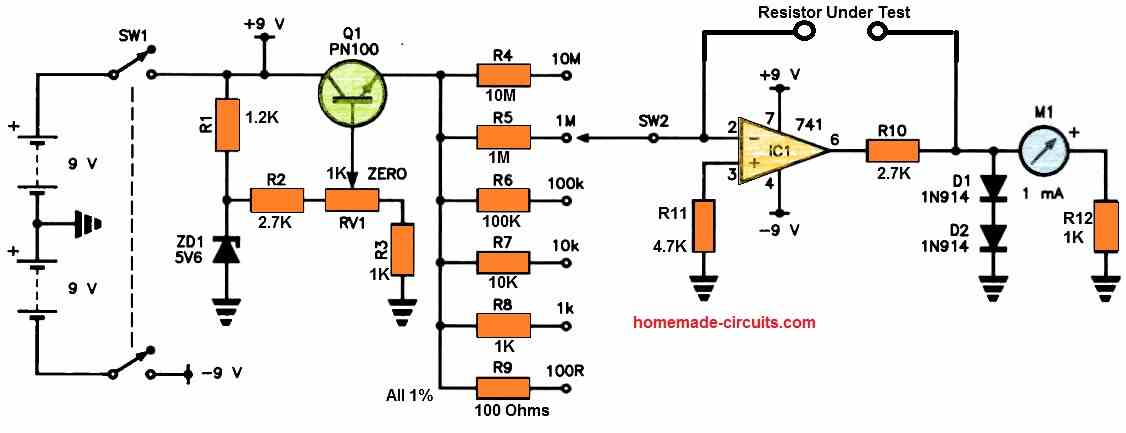
This will cost less!
The inverting input of op-amp IC1 receives a constant current drive from a constant current source made up of Q1 and a few range resistors [R4 to R9].
The resistor which needs to be tested is attached between the op- amp's inverting input and output.
The output voltage will be directly proportional to the ratio between the unknown resistor and selected range resistor value.
R10 restricts the permissible output current of IC1 whereas diodes D1 and D2 minimize banging of the meter needle by limiting the voltage across the meter circuit.
All of the range resistors can be 1 or 2%; therefore you don't need to go ahead of Class 2 meters, that come with a full-scale accuracy of 2% since they are expensive and difficult to get.
The source current may be set using RV1, which also allows the meter to be set to zero. To power the circuit, a couple of 9 V transistor radio batteries can be utilized.
Datasheet
For the complete IC 741 Datasheet, you can refer to the following article:
Questions & Answers
Please I need a op amp circuit that can compare 2-4 batteries. Thanks.
Hi Seun,
I did not understand your question. How do you want to compare 2, 4 batteries using op amp??
Hey sir. Concerning the sensory plate of the proximity sensor, is it okay to use a bass pick-up as the metallic plate?
Hi Davis, any metallic plate will do, brass will also work.
How about creating a Swagatam Electronic labolatory in Zambia.
Sounds good, who will manage it?
Hi Swagatam, could you suggest a circuit for testing a 741 to see if it is okay the reason being that I have a few of them in my collection and wanting to know if they are okay to use. I am also wanting to build a non contact AC voltage detector that uses a 5v piezo buzzer and a led for audio and visual detection.
Regards
Geoff
Hi Geoff, you can connect the opamp as a comparator and check the output response.
connect any one of the input pins between the junction of two 10k resistors whose ends are connected to the supply rails.
connect the other input terminal to the center lead of a 10k preset or pot whose outer terminals are also connected with the supply rails….
connect a couple of LEDs, one from (+) to opamp output, and another from opamp output to (-), both having there own 1K resistors.
now flipping the pot to and fro should light-up/shut-off the Led alternately…proving the correct working of the opamp.
Sir, please do a circuit on bass booster using opamp ic741
Dear sir how to make voltage amplifier
when input voltage 1 V DC 200uA and Need a Output Voltage 2V DC 100mA
that's impossible, unless an external power supply is used.
Is the power supply's output regulated?…
How do I calculate the current limiter R6?…
It's variable voltage but not current?…
tnx for the patience 😀 Engr. Swagatam…
thanks Eshkariel 🙂
yes the output will be regulated as long as the 24V or whatever input is fed is constant.
R6 = 0.6/current limit value
Hi sir, how to increase .5Vtoo 5v.? In my project i use piccontroller and sensor. My sensor gives oly .5v oly. So controller couldn 't take this voltage. How to boost up this voltage that can detect controller ..? Soundhirarasans@gmail.com… thanks in advance ….
Hi Soundhirarasan, you can try a joule thief circuit as shown in this article:
https://www.homemade-circuits.com/2012/10/1-watt-led-driver-using-joule-thief.html
sir, i want to build a parametric oscillator circuit. using a variable inductor. please can you provide me a circuit diagram
Ignatius, using a variable inductor might not be possible for me, but here's one that uses a different principle you can check it out:
https://www.homemade-circuits.com/2014/06/making-ultrasonic-directive-speaker.html
sir, I want to make an portable charger for a mobile by using a solar cell ,wind energy ,a battery and IC 741 so can you provide us circuit diagram and the list of component related to it as early as possible
sanket, you can try the following circuit:
https://www.homemade-circuits.com/2015/09/solar-wind-2-input-hybrid-battery.html
Hi swagatm,
AS I mentioned that the Volts from the pulse coil at low rpms would be 200-250mv, may be 150 mv as well. So I have to eleminate R3 and the relay+diode and connect the collector pin of bc557(PNP) to the base of the PIC which will deliver 5 volts pulse to the PIC. Correct me If I am wrong.
Now the next querry is at highr rpms when the voltage from the pulse coil is 8-10 volts, Do I have to add a zener between the pulse coil and R1.
Waiting for your reply
Hi Akashdeep, yes that's correct……. by "base of PIC" did you mean the input of PIC?
If the supply to the referred transistor circuit is fed with 5V then the input variations will not matter… . The collector of BC557 will always generate 5V regardless of the input variations.
for a safer response make R1 = 100K
Hi Swagatam,
From the pulse coil of my bike I get a pulse of 250 mv at low rpm which is not sufficient for the micro-controller to sense. But at higher rpms The pulse goes up to 8-1- volt.
I thought of adding an op-amp in between the Pulse coil and the micro-controller. So the pulse coil, a resistor, then 4007 diode, then a zener then op-amp and then to micro-controller. Will you plz specify how it should be with the schematics and the component values plz. The power source would be a 12 volt battery.
Hi Akashdeep,
opamp may not be required for such a simple enhancement, you can use two BJTs and configure them as shown in the following example article:
https://www.homemade-circuits.com/2011/12/simple-and-useful-transistor-latch.html
Eliminate R3 and the relay+diode, those are not required, now you can use the collector of T2 for triggering the MCU.
sir its me again
i have a low pass filter using [jrc4558] its is for home made [ home theater sub woofer] , its working but the problem is that i can here little transformer dramming coming from the sub woofer] its sounds mmgmmgmgmgmm….
my question is how can i reduce this problem because its really bad especially working with power amplifier and opm
joshua, you can make and install a 50Hz notch filter circuit for sinking the interference or use an smps based circuit for powering the amp
Thank you very much sir . Once I done I let u know the result .
Sir, Tks for ur valuable comments . I understood. Ic 741 is for 1 o/p only . for my circuit I need to measure two resistors only . 1.2k & 4.5k only. Is there any dual op amp ic ? Pls help me n post the circuit sir .tks in advance.
Prabhu, you can use LM358 IC for it.
you can try the first design shown in the following article:
https://www.homemade-circuits.com/2011/12/how-to-make-simple-low-battery-voltage.html
replace the zener diode with 1K or 10K and adjust the 10k preset either to shut off or light up as you want in response to the selected resistor.
Hi sir , by using op amp can I measure resistance . I need a o/p in a led indication. Fixed value ..let say if 1k red led need to light up if 10k green led need to light up …..pls help ..tks.
Hi Prabhu, yes it can be done. But only for a single resistor for a particular setting, you cannot get multiple indications from one opamp at a time
hi sir
can you send me a circuit of pre amplifier which gives output of bass only
Hi Joshua,
you can try this circuit:
https://www.homemade-circuits.com/2013/06/make-this-low-pass-filter-circuit-for.html
You will need to make a small ferrite transformer for stepping it up. You can try the concept discussed in the following article:
https://www.homemade-circuits.com/2012/10/1-watt-led-driver-using-joule-thief.html
I am sorry, i am comfortable interacting only through my blog.