This 150 watt amplifier is designed to provide a full 150 watt peak to peak music power amplification over a 4 ohm loudspeaker.
In this post I have explained how to make a simple 150 watt power amplifier circuit using a typical OCL design which ensures cheap layout and use of minimum components, with high reliability.
Introduction
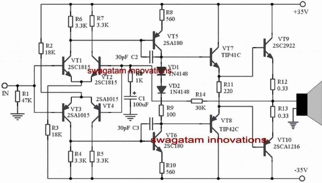
Referring to the figure a perfectly symmetrical OCL based amplifier can be seen , using discrete components suitable for all electronic enthusiasts and hobbyists for going through an in-depth practical study with its topology.
This OCL amplifier circuit is a mid-range power amplifier capable of delivering a good 150 watts of power due to its symmetrical structure, wide frequency response, simple layout and so on. The sound quality will be quite satisfactory, and comparable to other equivalent high-fidelity amplifiers normally preferred by the users for home use.
How the amplifier circuit works
The first stage of the circuit can be seen built with a complementary symmetrical differential configuration, each of the BJT channels using 2SC1815, 2SA1015 consume about 1mA, while in the quiescent state
The next stage is designed for handling the voltage amplification and this also makes use of a complementary push-pull design, through a set of high power complementary pair of BJTs namely A180, C180, which runs using a current of about 5mA.
The two 1N4148 ensure a drop of 1.6V required for biasing the relevant bases of the complementary BJTs.
The next two complementary power BJTs involving TIP41C, TIP42C create the driver stage or the intermediate buffer stage fo the last power transistors.
The inclusion of this high efficiency buffer/driver stage becomes one of the main features of the modern OCL amplifier design, which helps to offer a high load impedance, and thereby ensures a very stable Higher gain amplifier output stage.
Additionally this type of capacitor less topology also ensures a lower output resistance across the output power transistor stage, which in turn helps the output junction capacitance Cbe charging rate to become faster, thus improving the overall transient characteristics and frequency stability of the circuit.
However the operating current of this stage can be slightly higher, at around (10-20) mA, for each of the channels which may sometimes go as high as 100mA under higher full volume, this happens because the specified quiescent current may be capable of saturating the output stage to the most optimal levels.
As can be witnessed in the given 150 watt amplifier circuit diagram, the emitter resistances of the driver stage employs a floating termination, and these are not connected with the earth line, and this causes the amplifier to operate typically in the Class A range, and ensure a maximum bias voltage for the output stage.
The power output stage is wired using the traditional complementary capacitor less design and features an FT (frequency transition) level of as high as 60 Mhz, across the BJTs C2922, A1216, through a quiescent current consumption of around 100mA.
The amplifier also employs a negative feedback loop across the output stage and input inverting stage, which sets the amplifier to a gain level of approximately 31.
Part Equivalents
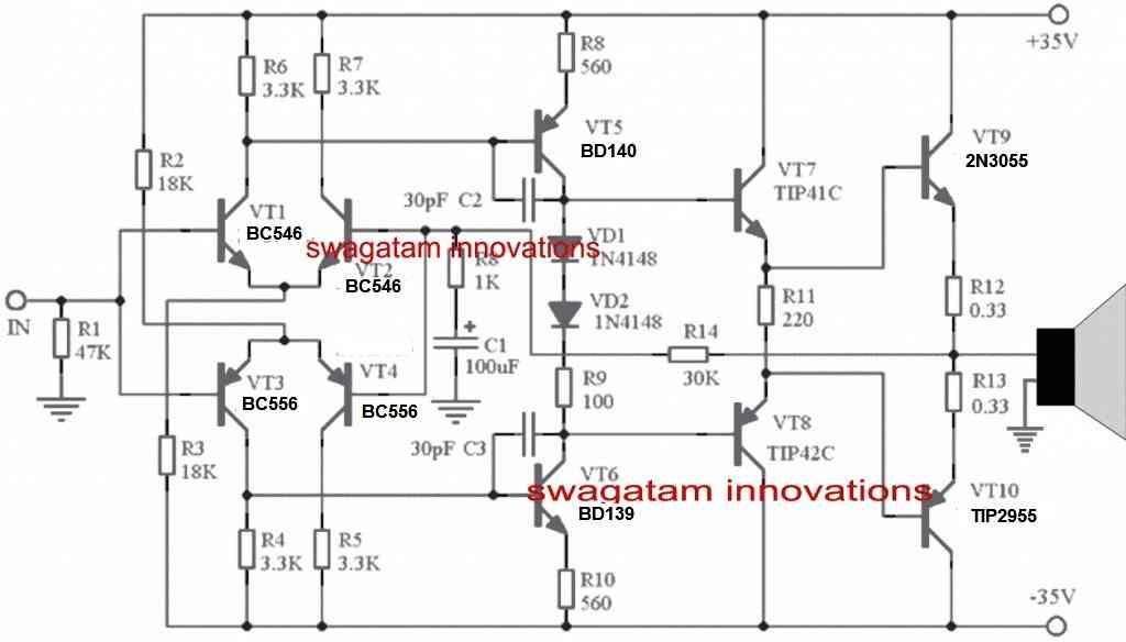
If you find it difficult to get the parts mentioned in the diagram, you could replace them with the following equivalents.
- VT1, VT2 = BC546
- VT3, VT4 = BC556
- VT6 = MJE340
- VT5 = MJE350
- VT9 = TIP3055
- VT10 = TIP2955
How to Convert into Higher wattage Power Amplifier
The title of the article suggests that the mentioned design is intended for delivering 150 watts of power, but in reality the specs are actually never restricted for such designs. You can easily upgrade the circuit to produce much higher outputs simply by increasing the voltage upto 90V.
The power devices mentioned in the above parts list are specifically selected to handle higher voltages and to enable the required upgrades.


Questions & Answers
can i add 4 pair of 2n3055and 2n2955 (total 8 transistor) at output stage?
Dear sir,
The output voltage of my available transformer is 35v,0v,35v(A.C.). How can I use this transformer for powering this amplifier circuit? I wish to connect a 33v, 1w zener diode in series with a suitable value of resistor in which the points of R4,R5 and R6,R7 after seperating those points from the power output section (That means I wish to seperate differential section from the main +V and -V). Please tell me is it suitable?
Hi Sanjeeva,
You can connect the 35V outer taps of the transformer with a bridge rectifier/filter capacitor, and use the +/- outputs of the bridge rectifier to power the +35, -35V terminals of the amplifier, and connect the center 0V tap of the transformer with the ground line of the amplifier…sorry I did not understand why do you want to connect the zener diode?
Dear sir,
Thanks a lot for your answer. I think that you got confuse from my question. Simply I can explain what that I mean. For few months ago, I made your circuit and used a 20V,0,20V transformer for powering it. After rectifing and smoothing it was about +28V,0,-28V and performance of the circuit was quite enough. This time my transformer is 35V,0,35V(A.C.). After smoothing it will be about +50V,0,-50V. Is that voltage damage the components in the circuit? What is the maximum possible voltage to power this circuit without damaging the components.
Thank you E.A. for the clarification,
If you replace the input side NPN transistors with BC546, and PNP with BC556, and the center transistors with BD139 for NPN, and BD140 for PNP, and the extreme right side output transistors with TIP35 for the NPN, and TIP36 for the PNP… then 50V would work fine, and in fact increase the overall output power of the amp significantly…
Hi, no, that is not possible. Adding parallel devices in an amplifier is possible only if the devices are MOSFETs.
Hallo saya dari indonesia …ada gak ya skema 1000watt yang simpel….
Hi, you can refer to the following article:
https://www.homemade-circuits.com/1000-watt-to-2000-watt-power-amplifier-circuit/
Hi sir, if I use 2sc5200&2sa1943 at output stage, tip12 tip42 as transistor driver.
The supply to use equal to 70v DC,
How much will be power output
Hi Alexis, I am not sure whether this circuit can handle 70 V or not so cannot say how it will respond?
Hi Sir, what should be the wattage of R12 & R13, Thank you!
Hi Rafael, you can use 3 watt resistors.
Hello sir, pls how can I identify and then adjust the quiescent current here, the reason is because the output transistors get hot quickly even without load
Hello Joseph,
The two series diodes ensures that the quiescent current is automatically adjusted to the correct point. You can try adding one more diode in series and check if that works.
Or alternatively replace the two diodes with a 1K preset and carry out the following adjustment procedures:
it can be done through the following steps:
Short the input to ground
Short the speaker terminals.
Connect a 100mA small bulb in series with both the +/- supply lines.
Switch ON power, you might see the bulbs illuminate.
Now adjust the 1k preset until the bulb just shuts off….the quiscnt current set now.
Replace the bulbs with fuses, remove the shorts at the input output points and operate the amplifier in the normal way.
Hello,, I am from Philippines,, can I increase b+voltage up to 90volts,and the output wattage increas?
Hi, No, I don’t think 90 V can be used in this design unless the transistor and the resistor values are changed significantly.
I want to show that with + 35v 0 -35v in the power supply, the solution in the BIAS circuit to NOT have crosover distortion from 5 khz and 20 khz that originally DOES have, The solution is 3 1N4007 diodes and 1 resistance of 100 ohms in series. From end to end there should be 2.3 volts dc. Thus the circuit has Zero percent crossover distortion. Test with oscilloscope .
Thank you for the information!
Hi , I am very interested that you can see the images of the 150 watt OCL circuit on my fully calibrated oscilloscope, with a sinusoidal signal of 10 khz. The circuit behaves very strange, it compresses the negative hemicycles and has crossover distortion as the power increases. I am very interested that you can guide me to solve this problem. The resistances are 1%. Answer me and tell me an email to send you the images of my oscilloscope. Thanks . Peter .
Hi, I am really sorry, I don’t think I would be able to help you to solve your problem, because I am not an expert in the audio field
Hi , I need to know what is the A180 and C180 transistors ??? . Answer me please . Thanks . Pedro.
I like so much the circuit .
Hi, you can replace them with BD139 and BD140 transistors
Hi , I need to know what those A180 and C180 transistors are ??? . I have searched the internet for information and all I see is that the 2sc180 are germanium and only 25 volts. Please answer me. Thanks . Peter .Have you made the pcb design ??? . I made one, but the distribution of pieces in the complementary double pair differential has been that the negative hemicycles have a great oscillation. I am not an electronic professional. I am a classical piano teacher who likes electronics.
I have replaced the old parts with new parts, you can check out the diagram below:
What are the advantage of double differential at the first stage compared to those that use single differential
The advantage of double-differential first stage compared to a single-differential stage is basically an improved noise rejection and lower distortion.
what are the fuction of R1 and R14
which one will adjust gain
R1 ensures the output BJTs are in a non-conducting state in the absence of an input signal.
R14 is the feedback resistor that feeds a portion of the output voltage back to the input stage of the amplifier. By adjusting the feedback resistor we can control the overall gain of the amplifier. This ensures, the output signal doesn’t become excessively amplified, which could lead to distortion or clipping.
r14 is just 30k does it mean the signal is amplified 30times which is equal to 29.5dB?
I’ve seen many amplifier with r14 as 47k ,100k , or even 22k
some bigger amp have just 20k there ..and these 100w amp have even 100k
I thought R1 is the resistor which control gain because of its value in many amp you may find 22k,30k,47k or 100k to bigger amp!
R1 does not control gain, it is the feedback resistor which controls the gain.
In the above circuit R14 controls the gain.
Gain = (R14 + R8) / R8
C1 can also affect gain.
R14/R8 = 30k
so for an output of 150w at 4ohms my signal should be 816mV
sir then why bigger amps have much smaller value there at R14 ? does it mean it has lower gain than small 100w which I sometimes found 100k there
Eminentia, Different power amplifiers may have different feedback ratios, and the C1 value also plays a role in defining the gain, so without checking the values of each components in the loop, it can be difficult to assess the gain of different amplifier configurations.
thank you,, I have another question
am having a 28 0 28 @ 1.8A transfomer ..after rectification it will be somewhere 39 0 39 then when you take that 39v × 2 × 1.8A is 140w
but transfomer is only 100VA
can you explain to me what if I hook up a 100w amplifier or 150w how much power can I get from that transformer
how much current can 1943 or C5200 pull/use
others say its 1.25A
so my old math for a pair of A1943/C5200 was multplying voltage after rectification eg 40v ×1.25× 2 =100w
was I wrong?
can a single transistor takes more than that current may be 3 ,, so that I will only take one rail eg 40v × 3A because in push pull they can’t conduct at the same time
The current and voltage consumption will depend on the audio source amplitude level or the mV level. For higher input voltages the V x I will be rise and the for the lower voltage it will drop. So, the consumption cannot be constant.
During peak input voltages the consumption will depend on the speaker Ohms.
As for the transistors, without heatsink it cannot handle more than 20% of its rated value.
Is there any simple calculation to calculate output power through number of transistors and voltage supplied assuming transfomer have unlimited current
Eg how much power can I get from 2 power transistor amplifier with 40± assuming transfomer can supply any current eg 5A
Eg 2: how much power from two pair of power transistor (i.e 2 1943 and 2 C5200) with 35v±
You can get alternately 40 x 5 = 200 watts from the transformer, if the transformer is an ideal transformer.
For the transistor, it will depend on their Collector emitter voltage and current ratings, and the gain of the transistor.
You must multiply 39 only once with 1.8, because during push-pull action from the speaker, only one supply will be amplified at a time.
so 39 * 1.8 = 70.2 watts is the right answer.
Hi, can we increase the otuput transistors with several pairs?
Hi, I don’t think that may be possible since they are BJTs, you can try replacing VT9, VT10 with MOSFETs for increasing the power
hi bro,i have a transformer with output 45vac 0 45vac 20a..please give me a amplifier circuit that can handle such transformer and have output of 1000w power..please need a clear circuit i make my own amp
What will happen if I will add another pairs in parallel to VT9 and VT10?
It might not work until the associated resistors are also changed
Thank you sir. So, this might be the reason why every time I add another pair of output transistors to an OCL amplifier, the driver transistor explodes.
No problem Aldrin, yes that could possibly be the reason!
Hi, you can try the following design, although it uses 90V but 45 V can also be tried.
https://www.homemade-circuits.com/1000-watt-to-2000-watt-power-amplifier-circuit/
It is quite a good design.can anyone help me I have another version but I have problem with biasing 2sc2383 and A1013.
Dear sir…
There is a continues voltage out on speaker out without input.. and only npn power transister is heating when operating. But it works well.
Dear Rangnath,I wish I could help you but i can’t because the circuit is an elaborate one and judging the fault without testing the circuit practically can be very difficult.