• Skip to main content
  • Skip to primary sidebar

Homemade Circuit Projects

Need circuit help? Post them in the comments! I've answered over 50,000!

Blog | Categories | About | Hire Me | Contact | Calculators-online
You are here: Home / Automobile Electronics / 3-Pin Solid-State Car Turn Indicator Flasher Circuit – Transistorized

3-Pin Solid-State Car Turn Indicator Flasher Circuit – Transistorized

Last Updated on May 16, 2026 by Swagatam 6 Comments

Although, most of the car electronics have evolved into solid-sate versions, a turn indicator flasher unit is one device which still depend on a relay based design in many of the modern cars.

Table of Contents
  • Disadvantages of Relay Based Flasher
    • Advantages of Solid-State Flasher Circuit
    • How the Circuit Works
      • PCB Design
  • Solid-State Car Turn Signal Indicator using IC 4049

Disadvantages of Relay Based Flasher

There are a couple major disadvantages of a relay based electromechanical flasher unit:

1) First, these being mechanical in nature, go through rapid wear and tear and therefore tend to get damaged soon.

2) Secondly, the flashing rate from these electromechanical circuits are load, voltage and temperature dependent. Meaning, the flashing speed can get affected if the ambient temperature is high or if the battery voltage drops, or if the load exceeds a specified limit.

This also implies that if the user wants to flash all the 4 lamps together, he may find the flashing speed too fast and too slow.

Advantages of Solid-State Flasher Circuit

The 3 pin electronic solid state flasher circuit explained here is virtually free from all of these drawbacks. The repetition rate or the flashing rate from this design is practically independent of the supply voltage, ambient temperature, or the load (number of lamps connected).

The circuit also features a warning switch which seems to be very reliable and handy during emergency, or road accident situations. The switch bypasses the car switch and allows the lamps to run directly through the flasher, enabling all the 4 lamps to flash together, sending an SOS like signal during a nighttime road mishap.

In addition the specifications of this design conforms with all the current statutory requirements for car turn indicators.

The repetition frequency of 40 to 90 flashes per minute set in this unit is as per the advised range and also the circuit is designed in such a way that the indicators lamps switch ON instantly when the turn indicator switch is powered.

How the Circuit Works

The circuit is essentially an astable multivibrator built using a couple of CMOS NOR gates N1 and N2. N3, N4. Power transistors T1, T2 and T3 acts like a buffer stage for the output of this astable to operate the high wattage indicator lamps.
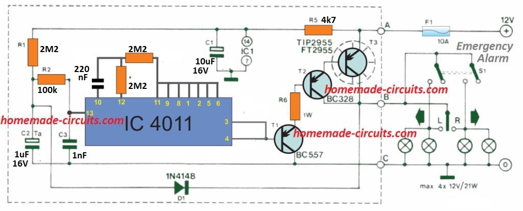
Whenever the indicator switch is toggled ON C2 discharges swiftly via D1 and the indicator lamps. Pin 13 of N1 turns high and its output becomes low. The gate N3 and N4 outputs consequently become high, switching on T1, T2 and T3 and turning ON the indicator lamps.

The astable is now initiated to switch at around 1 Hz frequency, causing the indicator lamps to blink on and off at the same rate.

When the hazard warning switch, S1, is turned on, the circuit continues to function in just the identical manner except that all 4 indicator lamps now get linked in parallel and they all begin flashing simultaneously.

T3, which is responsible for handling maximum load current, should be installed on over a heatsink.

When a metallic enclosure is employed to accommodate the proposed 3 pin solid-state flasher circuit then T3 could be clamped to the surface of the case with screw/nut and insulation kit.

The current (amps) through the terminals attached to points A and B can be pretty substantial (up to 8 A) therefore thick wires should be used for these cable connections. The positive battery supply terminal should be installed with a 10 A fuse if it is not included originally.

PCB Design
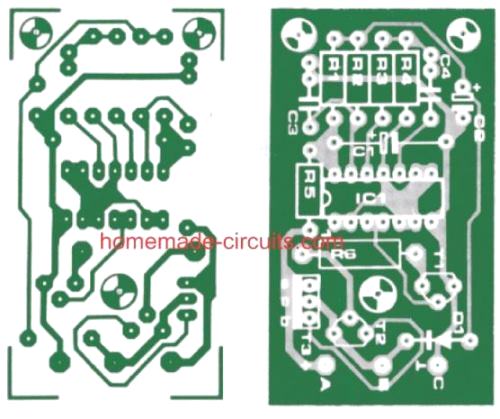
Parts List

Resistors:
R1,R3,R4 = 2M2
R2 = 100 k
R5 = 4k7
R6= 120 Ohm (1 Watt)
Capacitors:
C1 = 1Oµ/16 V
C2 = 1 µ/16 V (tantalum)
C3 = 1 nF
C4 = 220 nF
Semiconductors:
IC1 = 4001 (B)
T1 = BC 557, BC 177
T2 = BC 328, BC 327
T3= FT 2955 or TIP 2955
D1 = 1N4148

Solid-State Car Turn Signal Indicator using IC 4049

A single IC 4049 and a few passive components is all that you need to build the following super easy car 3-pin turn signal indicator circuit.
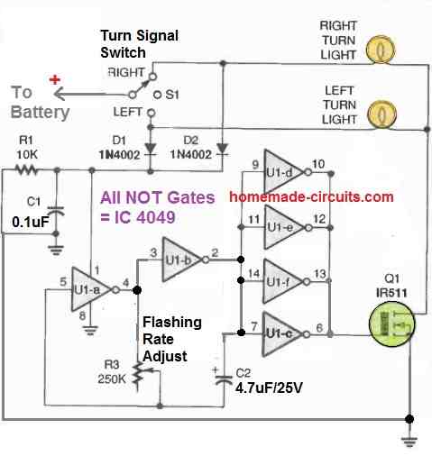
A single 4049 IC consists of 6 nos of NOT gates.

All these NOT gates are included in the diagram. U1a and U1b NOT gates are configured as oscillator, which generates the flashing rate or the flashing frequency for the indicator bulbs.

The remaining NOT gates are simply used as buffers, to finally power the attached MOSFET.

Since a MOSFET is used, the flasher circuit becomes fully solid-state.

The oscillator frequency activates the buffer, and the frequency is supplied to the MOSFET gate via the buffer stage.

The MOSFET also starts oscillating with the same frequency and powers the indicator lamps ON/OFF.

The switch S1 is the turn signal switch which selects the right or the left flasher bulbs depending on which side the car is turning.

The pot R3 can be used to adjust the flashing rate of the indicator bulbs as per your own preference.

You'll also like:

  • carvoltagestabilizercircuitMake this Voltage Stabilizer Circuit for Your Car
  • codeswitch 1Simple Ignition Code Lock Circuit for Automobile Protection
  • Motorcycle Regulator, Rectifier Tester Circuit
  • Automotive Sensor Substitute Circuit Diagram

Filed Under: Automobile Electronics Tagged With: Flasher, Indicator, Solid, State, Transistorized, Turn

About Swagatam

I am an electronics engineer and doing practical hands-on work from more than 15 years now. Building real circuits, testing them and also making PCB layouts by myself. I really love doing all these things like inventing something new, designing electronics and also helping other people like hobby guys who want to make their own cool circuits at home.

And that is the main reason why I started this website homemade-circuits.com, to share different types of circuit ideas..

If you are having any kind of doubt or question related to circuits then just write down your question in the comment box below, I am like always checking, so I guarantee I will reply you for sure!

Previous Post: « 4 Solid-State Car Alternator Regulator Circuits Explored
Next Post: Simple Frequency Meter Circuits – Analogue Designs »

Reader Interactions

Questions & Answers

Total Posts: 6
Newest Oldest
Luciano
February 12, 2022 • 5 years ago #112409

Hi, will this work with LED turning lights? Thanks

Reply
SwagatamAdmin
February 13, 2022 • 5 years ago #112531

Hi, you will need to replace the lamps with LED modules

Reply
William A Grotts
September 1, 2021 • 5 years ago #96086

Do I understand correctly that when the base of t1 is drawn LOW, it turns ON the lamps?
‘RileyG’

Reply
SwagatamAdmin
September 1, 2021 • 5 years ago #96092

That is correct!

Reply
William A Grotts
September 1, 2021 • 5 years ago #96142

Then I should be able to use the transistor part of this circuit triggered by an opto isolator that is controlled by the turn signals (object is to not add any more current drain to the turn signals as they stand as they are ‘computer controlled’ and shut off completely if an over current situation is sensed.)

Thank you!
RileyG

Reply
SwagatamAdmin
September 1, 2021 • 5 years ago #96147

Yes, that may be possible!

Reply

Need Help? Please Leave a Comment! We value your input—Kindly keep it relevant to the above topic! Cancel reply

Your email address will not be published. Required fields are marked *

Primary Sidebar

My YouTube Channel

Circuit Simulator: Draw and Simulate Schematics

circuit simulator image

Categories

  • Arduino Projects (95)
  • Audio and Amplifier Projects (134)
  • Automation Projects (18)
  • Automobile Electronics (104)
  • Battery Charger Circuits (90)
  • Datasheets and Components (109)
  • Electronics Theory (151)
  • Energy from Magnets and Earth (43)
  • Games and Sports Projects (11)
  • Grid and 3-Phase (20)
  • Health related Projects (27)
  • Home Electrical Circuits (13)
  • Indicator Circuits (16)
  • Inverter Circuits (98)
  • Lamps and Lights (161)
  • Meters and Testers (72)
  • Mini Projects (28)
  • Motor Controller (68)
  • Oscillator Circuits (30)
  • Pets and Pests (15)
  • Power Supply Circuits (91)
  • Remote Control Circuits (50)
  • Security and Alarm (65)
  • Sensors and Detectors (107)
  • SMPS and Converters (46)
  • Solar Controller Circuits (62)
  • Temperature Controllers (44)
  • Timer and Delay Relay (51)
  • Voltage Control and Protection (44)
  • Water Controller (37)
  • Wireless Circuits (31)

Subscribe to get New Circuits in your Email

Other Links

  • Privacy Policy
  • Cookie Policy
  • Disclaimer
  • Copyright
  • Videos
  • Sitemap

People also Search

555 Circuits | 741 Circuits | LM324 Circuits | LM338 Circuits | 4017 Circuits | Ultrasonic Projects | SMPS Projects | Christmas Projects | MOSFETs | Radio Circuits | Laser Circuits | PIR Projects |

Recent Comments

  • Swagatam on About Me
  • chukwuamaka on About Me
  • Swagatam on Police/Ambulance Siren Circuit with Rotating Beacon Light
  • Swagatam on Room Air Ionizer Circuit – For Pollution Free Living
  • Swagatam on Understanding Motorcycle Voltage Regulator Wiring

Social Profiles

  • Twitter
  • YouTube
  • Instagram
  • Pinterest
  • My Facebook-Page
  • Stack Exchange
  • Linkedin

Calculators

  • ZVS Induction Heater + Tank Calculator Tool
  • Zener Diode Calculator
  • Wire Current and Thickness Calculator (Ampacity Calculator)
  • Voltage Divider Calculator
  • Transistor Base Resistor Calculator
  • Transistor Astable Multivibrator Calculator
  • TL431 Calculator
  • Solar Panel, Inverter, Battery Calculator
  • Ferrite Core Air Gap Calculator Tool
  • Parallel MOSFET Calculator Tool: How to Connect MOSFETs in Parallel Safely
  • LC Resonance Calculator for EV Battery Charger Circuits
  • LED String Series Resistor Calculator
  • PFC (Power Factor Correction) Calculator Tool: 3kW
  • Passive Power Factor Correction (PFC) Calculator
  • LM567 IC Calculator Tool
  • SMPS Flyback Boost Converter Calculator
  • Shunt Resistor Calculator for Ammeters
  • SCR and Triac Gate Resistor Calculator
  • Battery Back up Time Calculator
  • Boost Converter Calculator (Non-Isolated)
  • Bootstrap Capacitor Calculator
  • Buck Converter Calculator
  • Buck-Boost Converter Calculator
  • Capacitance Reactance Calculator
  • DCM Flyback Transformer & Wire Gauge Wire Size Calculator Tool
  • Filter Capacitor Calculator
  • IC 4047 Calculator (Frequency and PWM)
  • IC 4060 Calculator
  • IC 555 Astable Calculator
  • IC 555 Monostable Calculator
  • IC SG3525, SG3524 Calculator
  • Inductance Calculator
  • Induction Heater Inductor and Resonant Frequency Calculator
  • Induction Heater Work Coil Calculator
  • Inverter LC Filter Calculator
  • LC Resonance Calculator
  • LED Current Calculator
  • LM317, LM338, LM396 Calculator
  • NAND/NOT Gate RC Values Calculator
  • NOT, NAND Gate Frequency Calculator
  • Notch Filter Calculator Tool
  • Ohm’s Law Calculator
  • Phase Angle Phase Shift Calculator
  • Power Factor (PF) Calculator
  • RC Filter Calculator
  • Reactance Calculator
  • Sine Table Calculator for SPWM Arduino Code
  • Small Signal Transistor(BJT) and Diode Quick Datasheet
  • SMPS Calculator for Toroidal Ferrite Transformers
  • SMPS Flyback Transformer Calculator – Design by Target Duty Cycle
  • TL431 Calculator
  • Op-Amp Hysteresis Resistor Calculator

© 2026 · Swagatam Innovations