This innovative Automotive Sensor Substitute Circuit explained in this article was thoughtfully designed and contributed by one of our passionate readers, Mr. August Peterson, who is an avid electronics enthusiast. It is a great pleasure to feature his creative work on this platform and I extend my heartfelt gratitude for his generous effort in sharing this project with our community.
Overview
The sensor substitute was developed to fit in place of passive type sensors to check if their performance was suspect.
This device cannot substitute active sensors, magnetic sensors or oxygen sensors.
This unit would be fitted in place of the suspect sensor and the expected correct value set on the potentiometer.
The engine would be operated to check its performance with the substitute sensor in circuit.
If the engine ran acceptably with the substitute in place of the sensor then a defective sensor has been confirmed!
A sound knowledge of generic sensor values is necessary to operate this device with success.
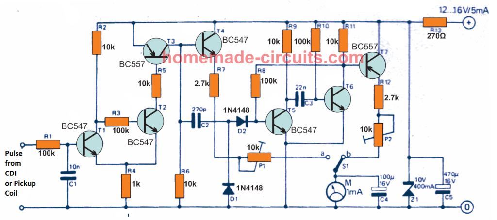
Circuit Diagram
How it Works:
Sensor Substitution:
The small device is attached to the car's circuit in lieu of the alleged passive sensor.
This ensures that the device assumes the function of the original sensor and is carried out via the input terminals.
Generation of Reference Voltage:
The output voltage of the replacement sensor is set by hand and adjusted using the circuit's potentiometer.
The original sensor's assumed typical functioning range is used to modify the level of the voltage.
A solid understanding of general sensor values is necessary, to adjust the potentiometer precisely.
Engine Testing:
The engine is started soon after the replacement sensor is installed and the voltage that is wanted is adjusted.
The replacement sensor creates the conditions in which the engine's performance is monitored.
Finding Faults:
If the engine runs nicely and within acceptable limits while using the replacement sensor, the original sensor had been malfunctioning.
On the other hand if the engine continues to fail, then there may be another problem in the system.
Limitations:
This circuit is unable to substitute active sensors, particularly magnetic or oxygen sensors, because these sensors possess distinct properties which the device is unable to mimic.
It is only useful for passive sensors which do not require electricity or complicated signal processing.
Correct functioning requires that the user knows the right voltage ranges for the sensor having been substituted.
Additional Information:
Operating Manual
The Automotive Sensor Substitute unit should be used in conjunction with the operating instructions by a person qualified in electronic automotive repairs and diagnostics.
We are not liable for any consequential losses, damages or injuries (to personnel or any third parties) whatsoever, whether direct or indirect, irrespective of cause or nature, relating to the application or use of any of the information or data provided by us, or the use of the Automotive Sensor Substitute unit.
Features
The Sensor Substitute unit cannot be used in place of:-
Engine Speed Sensor, Hall Speed or Reference Sensor, Inductive Speed or Reference sensor, Piezo Knock Sensor or Lambda (Oxygen) Sensor, or digital air mass sensor.
For testing purposes it is capable of substituting the analog three wire pressure, vacuum and position sensors with outputs in the 0 to 5 volt range.
(e.g. Manifold Air Pressure, Turbo Pressure, Throttle Position, Air flow, Air Mass and CO Potentiometer)
For testing purposes it is capable of substituting the two wire voltage divider type sensors.
(e.g. Engine Coolant Temperature, Intake Air Temperature, Fuel Temperature and Cabin Air Temperature sensors.)
It simulates the signal that the vehicle Electronic Control Unit expects, which means that you can substitute the sensor with this unit to confirm that the sensor is the cause of the problem.
The Automotive Sensor Substitute has no internal battery. It is fitted with a 100mA fuse to protect it against incorrect connection. You should however take care not to make incorrect connections to vehicle wiring that is associated with the Engine Control Unit.
The Automotive Sensor Substitute can be connected to a system and the vehicle driven so that the performance of the engine can be monitored in operation.
Connecting to the vehicle system
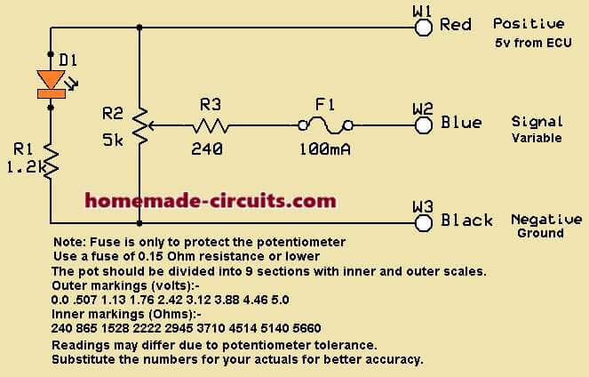
To substitute a two wire resistive sensor:-
(e.g. Engine Coolant Sensor, Intake Air Temperature or Fuel Temperature Sensor).
Note: The LED will not illuminate in this mode!
Turn the knob to the desired setting that you want the Electronic Control Unit to believe that the reading should be.
Disconnect the vehicle harness connector from the sensor that you wish to substitute.
Connect the Sensor Substitute ground and variable connection to the plug that was removed from the sensor.
Examples:-
- An engine coolant temperature of 20ºC = ± 2300 .
- An engine coolant temperature of 80ºC = ± 280 .
- Intake air temperature of 20ºC = ± 2300 .
- Intake air temperature of 40ºC = ± 1100 .
- Fuel temperature of 20ºC = ± 2300 .
- Fuel temperature of 60ºC = ± 520 .
If you have a diagnostic machine, set up to read actual values, you can confirm that the “temperature” is changing in sympathy with your setting of the knob.
To substitute a three wire analog electronic sensor:-
(e.g. Throttle Position Sensor, Air Flow Meter, Air Mass Meter, Turbo Pressure Sensor, Manifold Air Pressure or CO Potentiometer.
Turn the knob to the desired setting that you want the Electronic Control Unit to believe that the reading should be.
Disconnect the vehicle harness connector from the sensor that you wish to substitute.
Use a multi-meter set to DC volts, with the vehicle ignition switched on, and establish which terminal is the +5 volts connection. In some cases the engine must be rotating before the ECU will output the regulated +5 volts.
Establish which terminal of the harness connector is the ground (battery negative) connection.
The third connection will be the signal wire to the ECU.
Connect the Sensor Substitute ground, variable and hot to the plug that was removed from the sensor.
i.e. +5 volts, signal, ground.
The LED will glow to indicate the presence of the 5 volt regulated supply from the Electronic Control Unit.
Examples of sensor output:
- MAP sensor at atmospheric pressure = ±4.5 volts
- MAP sensor at 600mbar pressure = ±1.5 volts
- Turbo sensor at atmospheric pressure = ±1.5 volts
- Turbo sensor at 180kPa pressure = ±4.5 volts
- AMM at ±8kg/H air mass = ±1.4 volts
- AMM at ±250kg/H air mass = ±4.5 volts
- Air Flow Sensor at idle = ±1.2 volts
- Air Flow Sensor at full throttle = ±4.5 volts
- Throttle Position at idle = ±1.2 volts
- Throttle Position at full throttle =±4.5 volts
- CO Potentiometer at rich end = ±4.5 volts
- CO Potentiometer at lean end = ±0.5 volts
Run the engine and confirm that by substituting the suspect sensor, there is no longer a problem with the engine.
CAUTION:
If the Sensor Substitute unit is adjusted outside of the active sensor range (0.5 to 4.5 volts) it will cause the vehicle ECU to store a fault code for that particular sensor. You will then need the means to cancel the malfunction indicator light on the vehicle instrument cluster.
NOTE:
Most of the analog signals are changing depending on the engine load, or throttle position etc. therefore you would need to adjust the Sensor Substitute unit according to the changing conditions of the engine.
If the engine performs well with the Sensor Substitute unit connected and the original sensor disconnected, it confirms that the sensor was not functioning properly and needs to be replaced.
If the MIL (engine management light is illuminated while the engine is running, the substitution of a sensor may not be effective because the ECU will have substituted a default value inside the ECU. The signal from the sensor wire is not acknowledged in the ECU while the MIL is illuminated.


Need Help? Please Leave a Comment! We value your input—Kindly keep it relevant to the above topic!