In this article we study a simple 3.7V li-ion battery charger circuit with auto-cut off, which can be charged from your computer USB port or any other 5 V regulated source.
Simplest 3.7V Li-ion Battery Charger with Auto Cut-off using LM393 IC
If you do not wish to read the following long explanation, you can just watch the same in this video:
How it Works
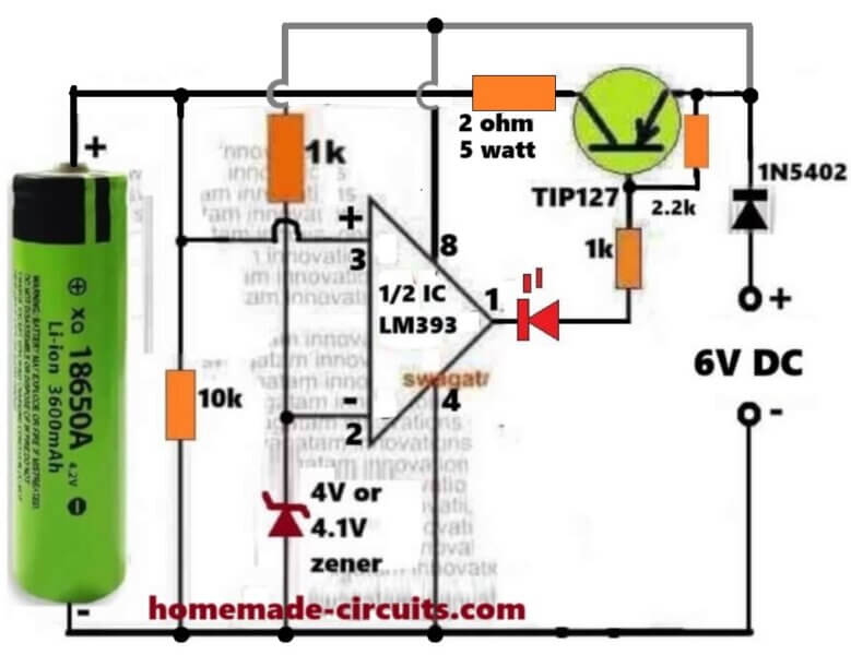
Here we see that this small circuit is made for charging one 3.7V Li-Ion cell like 18650 type, and we also see that it automatically stops the charging when the cell voltage becomes full around 4.1V or 4.2V.
So we can say that this is an automatic over charge protector using one half section of LM393 and one PNP transistor TIP127 which is working like a main current switch.
How The Whole Circuit Works Step By Step
Power Source And Battery Connection
We start by giving 6V DC supply to the circuit which acts like the charging input. The 3.7V battery is connected on the left side, so that the current flows from 6V supply through the TIP127 transistor to the battery for charging purpose.
Voltage Divider For Sensing Battery Level
The pin#3 of the LM393 is connected directly to the battery positive so it can sense the battery volatge level directly. So this way pin3 can sense the present battery level.
Reference Voltage From Zener Diode
We have one 4V or 4.1V zener diode connected to the inverting input pin2 of LM393. That zener is giving a fixed reference voltage which stays constant even if the battery voltage changes. So we can say that pin2 is having fixed 4.1V reference while pin3 is showing actual battery sample voltage.
Comparator Working Principle
Now we understand that LM393 is acting like one comparator, so it is comparing the voltages present at pin3 and pin2.
Case 1: Battery Voltage Is Low Or Discharged (below 4V or 4.1V)
So now that battery voltage is less than 4.1V, so voltage at pin3 is lower than voltage at pin2. Then the LM393 output transistor from inside becomes ON and it pulls pin1 to ground.
Because of this, pin1 becomes low and that low goes to the base of TIP127 through one 1k resistor. Since TIP127 is a PNP transistor, so its base getting low will make it conduct hard, so the current now starts flowing from emitter to collector and reaches the battery and the battery begins to get charged.
The LED also turns ON in this time because its cathode at pin1 goes to ground.
So we can now say in this condition:
LM393 output = LOW (Ground).
TIP127 = ON.
LED = ON.
Battery = Charging.
Case 2: Battery Voltage Is Full (4.1V Or 4.2V)
Now after sometime the battery gets almost charged, so that the voltage at pin3 becomes slightly higher than pin2. Then in this situation the internal transistor of LM393 turns OFF and its pin1 becomes open collector, that means pin#1 is now floating, without any logic level (open).
Now since pin1 is open, it cannot pull low anymore, so in this situation the 2.2k resistor now becomes active. That 2.2k resistor is connected from +6V to TIP127 base node so it pulls the base of TIP127 towards positive potential.
So when the base is pulled high and becomes near the emitter voltage, forces the TIP127 hard to stop conducting completely. So current cannot flow anymore from emitter to collector. The battery is disconnected from the charger. The LED also turns OFF because now there is no current path to ground through pin1.
So we can say now:
LM393 output = OPEN.
TIP127 = OFF.
LED = OFF.
Battery = Cut Off.
Role Of The 2.2k Resistor
Now we explain that 2.2k resistor which is very important here. It is actually working like a pull-up resistor, so that resistor is keeping the TIP127 base in one correct position depending on the output of LM393.
So when LM393 output is low, then that resistor becomes inactive because LM393 is grounding the base through the 1k resistor. So charging goes ON.
But when LM393 output is open then that 2.2k resistor pulls the TIP127 base high towards the emitter potential. So the transistor gets turned OFF strongly and it cannot conduct any leakage current. So this resistor ensures that the base never floats and the transistor never stays in half ON condition.
If that resistor is not there then the base of TIP127 may stay floating after LM393 goes open and this may allow some small leakage current to flow continuously, and the battery may keep trickle charging which is unsafe for Li-ion cell. So this 2.2k resistor saves the battery from such leakage problem.
Step By Step Summary Table
| Battery Condition | Pin3 Vs Pin2 | LM393 Output | Role Of 2.2k | TIP127 | LED | Battery |
|---|---|---|---|---|---|---|
| Low Or Discharged | Pin3 < Pin2 | Pin1 = Ground | Inactive | ON | ON | Charging |
| Fully Charged | Pin3 > Pin2 | Pin1 = Open | Active | OFF | OFF | Cut Off |
Main Points To Remember
So we now understand that LM393 works as one precise voltage comparator. The 4.1V zener sets the final cut-off limit. TIP127 handles the charging current. The LED gives visual indication of the charging status. The 2.2k resistor ensures proper base pull-up. And the diode 1N5402 stops the reverse current flow from battery to the circuit whenever the charger is unplugged.
Summary Of The Operation
We can now say everything in one line like this:
When the battery is below 4.1V then the LM393 output becomes low, then the TIP127 conducts, then the battery charges and LED glows. When the battery becomes full near 4.1V or 4.2V then the LM393 output becomes open, then the TIP127 stops conducting, then charging stops, and LED goes OFF.
So it works fully automatic and safe for 3.7V Li-ion cells.
How to Set up
It is actually very Easy.
During the setup procedure, do not connect any battery, instead, connect a variable power supply DC input on the battery side, meaning replace the battery points with this variable power supply DC input.
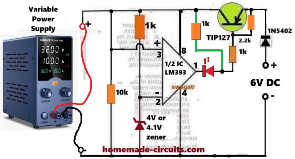
Connect a 1k temporary resistor between pin#8 of the IC and the anode of the red LED.
Keep the supply at zero volts and gradually increase it, until it reaches above 4.1V, or 4V.
At around 3V, you must see the LED turning ON.
Keep increasing the variable power supply voltage until it is above 4V or 4.1V. At this point you must see the LED shutting off.
That's all, this will prove that you LM393 based auto cut off is working correctly.
Now you can remove the above mentioned temporary resistor, and start charging any discharged 3.7V Li-ion battery using the normal configuration, as depicted in the above image.
Constant Current Version
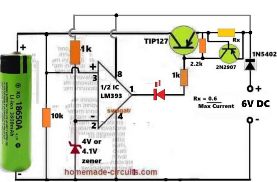
The above circuit can be further upgraded into a constant current version, as shown in the following diagram:
3.7V Auto Cut-off Circuit using IC 741
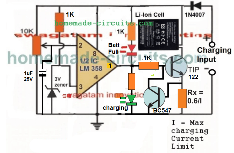
The following IC 741 auto cut off Li-ion battery charger circuit can be understood with the help of the following description:
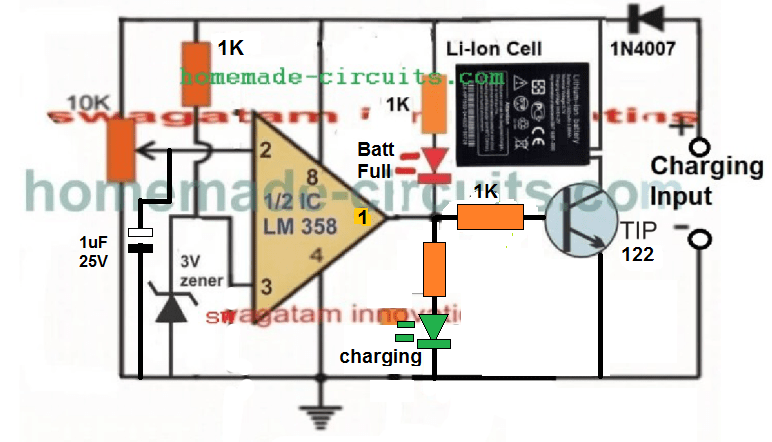
The IC LM358 is configured as a comparator. The IC LM741 is not used since it is not specified to work with voltages lower than 4.5V.
Pin#2 which is the inverting input of the IC is used as the sensing pin and is attached with a preset for the required adjustments and setting.
Pin#3 which is the non-inverting input of the opamps is reference at 3V by clamping it with a 3V zener diode.
A couple of LEDs can be seen wired across the output pin of the opamp, for detecting and indicating the charging condition of the circuit. Green LED indicates the battery is being charged while the red illuminates as soon as the battery is fully charged, and supply is cut off to the battery.
How to Charge using USB Port
Please remember that the charging process can be quite slow and may take many hours, because the current from USB of a computer is normally very low and may range between 200 mA to 500 mA depending on which number port is used for the purpose.
Once the circuit is assembled and set up, the below shown design can be used for charging any spare Li-Ion Battery through the USB port.
First connect the battery across the indicated points, and then plug in the USB connector with your computer's USB socket. The green LED should instant become ON indicating the battery is being charged.
You can attach a voltmeter across the battery to monitor its charging, and check whether the circuit cuts off the supply correctly or not at the specified limit.
Since the current from a computer USB can be quite less, the current control stage can be ignored and the above design can be much simplified as shown below:
Video Clip showing the automatic cut off action, when the Li-Ion cell is charged upto 4.11V:
Please note that the circuit will not initiate charging unless a battery is connected prior to power switch ON, therefore please connect the battery first before connecting it to a 5 V supply source.
An LM358 has two opamps which means one opamp is wasted here and remains unused, therefore LM321 may be tried instead to avoid the presence of an idle unused opamp.
How to Set up the above 3.7 V Li-ion Charger Circuit:
That's extremely easy to implement.
- First, make sure the preset is moved at the ground side fully. Meaning, the pin#2 should be at ground level through the preset initially.
- Next, without any battery connected, apply an exact 4.2 V across the +/- supply lines of the circuit, through an accurate adjustable power supply.
- You will see the green LED coming ON instantly.
- Now, slowly rotate the preset, until the green LED just shuts OFF, and the RED LED switches ON.
- That's all! The circuit is now all set to cut off at 4.2 V when the actual Li-Ion cell reaches this level.
- For the final testing, connect a discharged battery to the shown position, plug-in the input power through a 5 V source, and have fun watching the cell getting charged and cut-off at the stipulated 4.2 V threshold.
Constant Current CC Feature Added
As can be seen , a constant current feature has been added by integrating the BC547 stage with base of the main BJT.
Here the Rx resistor determines the current sensing resistor, and in case the maximum current limit is reached, the potential drop developed across this resistor quickly triggers the BC547, which grounds the base of the driver BJT, shutting down its conduction and charging of the battery.
Now, this action keeps oscillating at the current limit threshold, enabling the required constant current, CC controlled charging for the connected Li-ion battery.
Current Limiting not Required for USB Power
Although a current limiting facility is shown, this may not be required when the circuit is used with an USB since the USB already is quite low with current and adding a limiter may be useless.
The current limiter should be used only when the source current is substantially high, such as from a solar anel or from another battery
Improving the Circuit Further
After some testing it appeared that the Darlington transistor was unable to switch sufficient current to a Li-Ion cells, especially which were deeply discharged. This resulted in a difference in voltage levels across the cell, and across the supply rails of the circuit.
To combat this issue, I tried to improve the design further, by replacing the single Darlington BJT with a pair of NPN/PNP network, as given below:
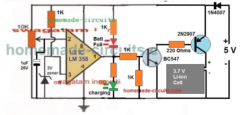
This design improved the current delivery significantly, and resulted in a reduction in the margin of difference between the battery terminal voltage level and the actual supply voltage level, and therefore false cut-off switching.
The following video, shows the test result using the above circuit:
Adding Current Control to the above Design
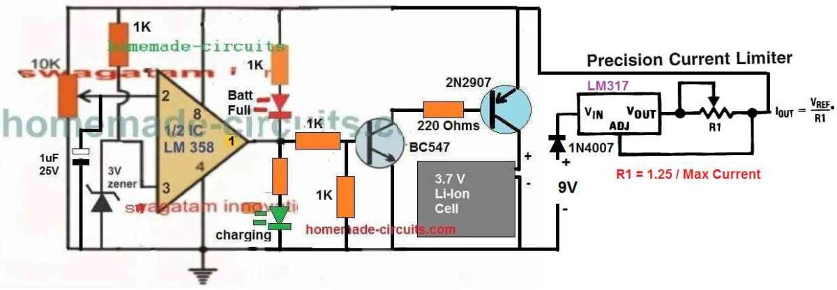
Using a 5V Relay
The above designs can be also built using a 5V, which will ensure the best possible current delivery to the cell and faster charging. The circuit diagram can be seen below:
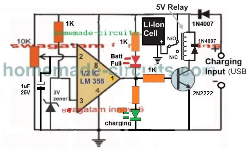
Please Note:
This article was substantially changed recently and therefore the older comment discussions may not match with the circuit diagram shown in this present updated design and explanation.
Another Ideal 3.7 V Battery Charger Circuit with Auto Cut-off
Here's a 3.7 V Battery charger circuit which looks perfect in for the automatic cut-off and a self-monitoring of the 3.7 V battery.
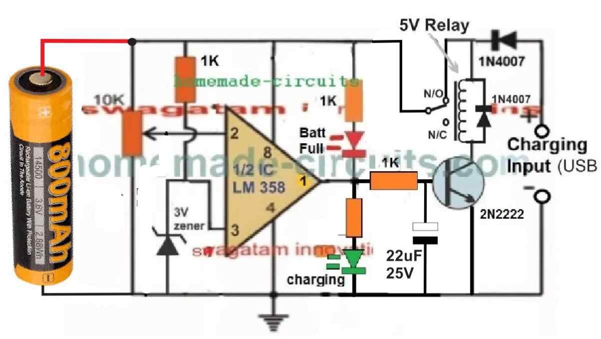
In the relay based circuit previous to the above design, there seems to a serious drawback.
In the previous design the battery needs to be connected first, before applying the input power. This is crucial, otherwise the relay can start chattering, if the power is switched ON first without a battery connected.
But in the above new design where the battery can be seen connected on the left side, the chattering of relay problem is completely eliminated.
Moreover, this design has an added advantage. The circuit will be able to continuously monitor the battery level and self-regulate the circuit to ensure that the battery is automatically disconnected when it reaches full charge level, and automatically connected to the supply when it is discharged to some lower level.
The input supply can can be from any 5V regulated source. However make sure the current spec of the supply is restricted to 0.5 C. Meaning the current of the 5V source must not be 50% of the battery mAh value.
How to Adjust the Preset
The auto cut off preset setting up is easy.
Initially, do not connect any battery or the input supply, and rotate the preset wiper to the ground level.
Next, take a variable DC power supply. Adjust its output to precisely 4.1 V, which is the optimum full charge level of a standard 3.7 V battery.
Connect this supply to the circuit from the left side, across the points where the battery is supposed to be connected.
You will see the GREEN LED illuminating. At this stage the relay must switch ON, however it won't since there's no 5V supply from the right side of the circuit. No worries, we can still setup the circuit by looking at the LEDs.
After this, slowly adjust the preset until the GREEN LED just switches off and the RED LED just switches ON.
That's all, the auto cut off set up is complete for the circuit.
Now, to test the circuit LIVE, you can connect a discharged 3.7V cell across the indicated points, and a 5 V supply from the relay side and see the actually cut-off happening, as soon as the battery is fully charged at 4.1 V.



Questions & Answers
The 118650 battery charger is voltage-controlled, NOT current-controlled. I question the validity of the entire article due to this simple, but crucial and important mistake.
if the 1k resistor connect to the + of battery like the circuits in video then diozener will change Voltage depend on the voltage of battery so the charging progress will stop sooner than theoricality.
The issue has been already addressed long back in the video comment section, and the comment pinned on top.
The correct circuit versions are given in the above article.
The ideal version is to use a preset for the over charge cut off threshold and a zener as the reference source, but since I wanted to avoid the preset adjustment hassles, I came up with these plug and play, preset less concepts.
Please explain your point, I will let you know where you are going wrong…
Dear Sir Swagatam
Hello, it is my duty to thank you for your kind assistance and the time you dedicated to responding to me and redrawing the circuits.
Your kindness is always present before my eyes.
I am 100% sure that the circuit is perfect and the semiconductors are indeed faulty.
God bless you
With warmest regards,#
Moe
Hello, Dear Moe,
I am extremely sorry and I admit that the previous circuit which I suggested you had a big problem and i am extremely sorry about all the hassles you had to face while testing the circuit.
I really don’t know how I missed this basic issue in the design.
In the previous circuit the 4V zener diode was linked with the battery, so how could the pin#2 of the LM393 get a fixed reference of 4V if the battery voltage was below 4V, so the IC could never do the comparison, and that’s why it kept failing.
The 4V zener resistor side must be connected directly with the input supply DC, and not with the battery so that pin#2 is able to get a fix reference, which could be compared with the battery voltage.
If you have time in near future then you can check this updated circuit and see if it works or not:
https://www.homemade-circuits.com/wp-content/uploads/2013/12/current-controlled-3.7V-li-ion-auto-cut-off-charger-circuit.jpg
Again, I am extremely sorry about all the trouble you had to face with the previous faulty design, due to my silly mistake…
It is my great pleasure Dear Moe, thank you so much for your kind words!!
God bless you too!!
Dear Sir engineer Swagatham
Hello
would you please tell me how much is the amount of the resistor which is connected to the positive pole of the green LDR? 1k?
Truly yours
Ali
Hi Ali, yes both the LED resistors are 1k.
Dear Sir
which N channel MOS i will choose. does it logic level or which is best?
Nitesh,
yes a logic level MOSFET would be better, such as this one:
https://www.digikey.com/en/products/detail/vishay-siliconix/IRLZ44STRRPBF/856860
Thanks
Dear Sir
i want to pass Power Bank 5V@9000 maH voltage to mobile device via Mosfet & gate of that mosfet is connected with mcu ( for on / off) . I am find out best method how can mcu &mosfet connetion each other May i ground one resistor also from Mosfet Gate ? there is facilities inside software for do logic high or logic low for mosfet operate at the time on timer & off timer.so pl give schamatics.
Hi Nitesh,
You can configure the circuit in the following manner:
Connect the N-channel MOSFET gate directly with the MCU output. No need of any pull down resistor.
Connect the source with the ground line of the MCU.
Connect +5V of the power bank with MCU (+) and connect the negative of the power bank supply with the MCU ground.
Connect this +5V also with the mobile charging input (+) and connect the mobile ground with the drain of the MOSFET.
What can be the substitute for the 150E resistor in the project in the link
https://www.homemade-circuits.com/wp-content/uploads/2024/11/3.7V-auto-cut-off-battery-charger-circuit.jpg
There is no substitute for this resistor, you can make it by adding a few assorted resistors in series parallel, slight difference is OK…
Which circuit (in your opinion) is best in factors like time taken for charging, safety
The following circuit is the best:
https://www.homemade-circuits.com/wp-content/uploads/2024/11/3.7V-auto-cut-off-battery-charger-circuit.jpg
Can we use a 1.67A Samsung adaptor
Yes, definitely you can use it…
Hi,
Does these circuits only work in fully empty batteries, 0V?
I assembed the 3rd circuit, for the 4th time, calibrated, with the preset at ground level (0homs), turn it on, green LED was on, move the preset until red LED becomes on, turning OFF green LED.
Connected a battery with only 2.3V, plug it to a 5V DC adapter and the red LED came ON, implying that the battery was charged….
Hi,
The circuit can be used to charge any 3.7V battery discharged below the set level (4.1V).
While setting up the preset, the supply input to the IC must be exactly adjusted at 4.1V.
I hope you have connected 1uF at pin#2.
Also, the input power supply current must be rated at 50% of the battery Ah.
If you are having difficulty setting up this circuit you can try the following one:
https://www.homemade-circuits.com/wp-content/uploads/2024/11/3.7V-auto-cut-off-battery-charger-circuit.jpg
Hi,
When you say preset to the ground, means that the resistor value between the center point and ground is 0 (zero).
Right?
If that is so, meassuring between the entry point of the adjustable resistor and the center point is about 3K, leaving 7K between the center point and ground.
Nélio Abreu
Hi Nelio,
Yes, that refers to resistance value between the center point and ground, which should be 0 (zero).
This is to be done during the setting up procedures of the preset. initially we must keep the preset fully towards ground and then slowly adjust it until the LEDs just changeover. This sets up the op-amp cut-off threshold.
There’s no need to measure the preset resistance, you can confirm the changeover through a variable power supply voltage and LED switching.
Hi, Swagatam,
I’m currently testing the 2nd circuit, with 2 minor changes:
Using TIP41C and without the base resistor and so far is working fine.
The 3rd circuit didn’t work
Best Regards.
Nélio
Hi Nelio,
A base resistor is strictly recommended for all BJTs, so please do not remove the base resistor.
The 3rd circuit should work, because it has been tested by me, you can see the adjoining video.
However, here’s another design which is very basic and very good, and virtually failproof, you can try it:
https://www.homemade-circuits.com/wp-content/uploads/2024/11/3.7V-auto-cut-off-battery-charger-circuit.jpg
Hi, the LED in the failproof circuit, is what? Charging LED or Charged LED?
How to I set the trimmer?
Best Regards.
Nélio
That LED indicates the battery is Charging, when it is shut-off means battery is fully charged.
To ensure that the LED does not blink ON-OFF at the threshold, you can connect a 100uF capacitor across the pin#2 of the IC, and ground.
Hi Swagatam,
Thanks for all the work you do here to help us all out.
I have a couple questions:
Thanks,
-G
Thank you Gee,
1) Yes, the last circuit can work with a solar panel. You can use any solar panel between 9V and 36V and use a 5V buck converter to optimize the solar panel output to 5V and then feed this 5V to the op amp circuit.
2) You can charge any number of batteries in parallel depending on the buck converter capacity.
il manque l’indication de la valeur de la résistance concernant la diode verte , est-elle
aussi de 1k ohms ? Merçi
Yes, the resistor connected with the green LED can be also 1k, but if you find the brightness low then you can decrease it to 470 ohms.
Hi Swagatam,
Is there a possibility that you have the LED’s identification wrong?
I mean, When it says Full should be charging and vice-versa.
Hi Nelio,
The LEDs are correctly configured to identify the results.
Initially when the battery is low, pin2 voltage is lower than pin3, so the output pin1 is high causing the green LED to illuminate and red to remain shut off.
When the battery is fully charge, the pin2 voltage becomes higher than pin3 voltage, causing pin1 to go low and the RED LED illuminates and the green is shut off.
So as per the above functioning the LEDs are labelled correctly.
I’m currently testing the 3rd circuit with 2N2907 and BC547. The results are the same. RED LED (in your schematic) is ON and GREEN LED if OFF.
Well that’s not that is happening in my circuit. When I connect the circuit with Battey in it, the RED LED (in your schematic) is ON and the green OFF (in your schematic)
That means you have either connected the pin2 and pin3 oppositely, or your preset adjustment is not done correctly.
What happens when you check with a power supply?
If the power supply result works then the battery result should also work.
You can see the video it worked perfectly for me.
With my PSU the result is the same. However it’s is charging, although I don’t if it’s correct.
I have an imagem but I can’t share it with you since your blog don’t allow it.
The opamp comparator works with a simple principle. When the battery is connected and power is switched ON, the battery immediately SINKS the current and causes the voltage to drop to its discharged level. When this happens the pin#2 voltage becomes lower than pin#3. So this is the crucial aspect. In your circuit when you switch ON power with the battery connected, is the pin#2 voltage dropping below pin#3???
This must happen, If this does not happening then the RED LED will never shut off.
If with PSU the same is happening then you might be missing something with the setting up procedure. Please follow the steps as explained under How to “Set up the above 3.7 V Li-ion Charger Circuit”
If you are having problems with the above circuits, you can try the following alternative design. For setting up, please replace the battery with the input DC from a variable power supply. Adjust the voltage to 4.1 V, keep the preset wiper arm to ground level, initially the RED LED will remain illuminated, now slowly adjust it until the LED just shuts off. Setting up is finished.
https://www.homemade-circuits.com/wp-content/uploads/2024/11/3.7V-auto-cut-off-battery-charger-circuit.jpg
Hi Swagatam,
I have assemble the 2nd circuit, calibrat it.
Put a 3.7V Li-Ion battery, type 16340 of 4800mAH to charge, connect a 5V adapter of 1A of current maximum output.
Left the battery there to charge with a capacity monitor and it hasn’t stop charging, after 2 days.
The capacity monitor indicates 4,338V, 99%. I have measure the voltage, to be the same.
The calibration was done using an adjustable PSU, set to 4.2V and 1A.
Hi Nelio,
The op amp has to operate and switch OFF the transistor if the 10K preset is correctly adjusted to 4.2 or 4.1 V. You can do one thing, connect another LED in series with the base 1K resistor of the transistor and monitor this LED response. This will ensure that no leakage or offset voltage from the op amp output can falsely keep the transistor switched ON.
Also while setting up the preset did your LEDs shut off correctly?
I would recommend you to set the cut off at 4.1V, so that it cannot exceed at the most 4.2V.
Yes. When I adjust the preset, the LED’s switch status. The RED turned OFF and the GREEN turned ON (in my circuit Colors are switched, since RED is consider danger, don’t touch, and Green is consider Ok).
I will try your sugestion of the 3rd LED and 1K resistor.
Thanks.
N.A.
OK, that means your op amp is good and working. Now you can just put another LED in series with the transistor base resistor and check the response.
Hi Swag,
In these circuits the capacitor is 1uF 25V.
Should it be these values?
Can I use 1uF 50V?
Thanks.
Best Regards.
Nélio Abreu
Hi Nelio,
As a rule of thumb, the capacitor voltage value must be two times the supply voltage, so for these circuits it can be any value higher than 12 V or 25 V. 50 V is fine.
Hi Swag,
Thanks
Best Regards.
Nélio Abreu
You are welcome Nelio!
Hi Sir, I have made an lm358 charger using BC 547anc 2n2907 transistors as your schematic and is fun in seeing the change over of led silently at full charge. But I have some thing to be clarified bu you sir. In the circuit, I hv used a 3.3v zener instead of 3v as given in the diagram. Will it affect the circuit in any way sir? And why you included the battery to be charged in the collector side of the PNP transistor and not on the emitter side? And if I needed a current control stage also in this circuit, where is it to be added ?If u can,pls suggest a modified circuit. Because I find some difficulty in dealing with the last stage PNP transistor to include the current control stage along with it. And afterall thanks so much for making us experiment and learn a lot sir.
Sir, thanks for your help and there is excellent current control when using LM317 as suggested by you.. And continuing my experimentation, i have also tried the relay cutoff circuit using 2n2222. But when the preset is adjusted to effect the cut off, the lm358 is going low but the relay is not being cutoff and the battery continues to be in charging mode. And then i added the 1k resistor across the base and emitter of 2222,which you have only included in the previous circuits and eliminated in this particular circuit. Now the correct cutoff is happening as required. Can you pls tell what is happening when the 1k is present and when it is not there.
Thank you Binoj,
I appreciate your useful observations and feedback.
Yes, indeed a base/emitter resistor must be included for the relay driver transistor to eliminate the offset voltage which is normally present at the output of most op amps.
This offset voltage is actually a small level of leakage voltage which continues to hang even while the output has turned low….this voltage is in the range of 1V or 1.5V which is enough to keep the transistor switched ON.
The base emitter resistor creates an appropriate resistive divider which effectively eliminate this leakage voltage and allows the transistor to be switched OFF correctly.
That’s great Binoj, glad you could make it successfully.
3.3V will also work since the cut off value is 4.2V. However, instead of 3.3 V zener you can use 3nos of 1N4148 diodes connected in series in place of the zener diode, but with opposite polarity.
Connecting the load at collector enables maximum current transfer due to minimum resistance and also there’s no voltage drop of 0.6 V.
For the current control, the best way id to add a LM317 current limiter at the input source. Here’s the complete diagram:
https://www.homemade-circuits.com/wp-content/uploads/2023/03/adding-current-limit-to-a-3.7-V-charger-circuit-1200×417.jpg
Hi ????
In number 1 circuit diagram below can I replace bc547 transistor with C945 transistor?
Yes, you can do that!
Hi Swagatham,
i am a fan of your site. and i am looking for a Charging circuit 3.7V 5A. i do EV vehicle repairs. for my testing purpose i want to build a customer 3.7V 5A auto cut-off battery charger. i hope you may have a circuit diagram for it. can you please provide me the correct link for it.
Regards.
Thank you M Ali,
I have designed the required circuit for you.
Please refer to the last updated circuit in the above article.
Hope it works for you.
Can I charge 3.7vilt Lion batteries in series with this circuit
Yes that may be possible.
Good day Sir, Please i need a circuit diagram of a Lithium battery charger for 3 lithium cells connected in parallel of 3.7v having a charging current of 5 amperes. Can you help me?
Hi Jason, you can build an LM196 based voltage regulator and adjust its output to precisely 4.1 V and use this 4.1V to charge your parallel cells. Make sure to keep the charging current at 50% of the battery’s total mAh rating. You may also have to use series resistors with each cell which must be calculated such that each resistor allows a current that’s only 50% of the cell’s mAh rating. So if the mAh rating of each cell is for example 1000mAh then the resistor must allow only 500 mA current to each cell.
If a 3.7 battery via a USB port is it possible to over do it? You state it may take many hours. Could you detail your longest time to date please so we know an approximate worst case possibility?
Is an intermittent signal always a sign of completion?
The USB port from my computer could supply only around 200 mA current, which took around 5 hours for the a standard 2400 mAh Li-ion to get fully charged.
Yes, the intermittent ON/OFF blinking of the LED indicates that the battery terminal voltage has reached the desired 4.1V or 4.2V full charge level.
Okay Sir.
Now I required at least 8volts across batteries. So, i have decided to use them as 3 series and 3 parallel connection so the voltages across the battery can 8.2v when it is fully charged. at what electrical settings I have to charge now for above Series-parallel connected batteries. if I set 4.1v and 1 ampere will all my batteries get charged?
For 3 series cells you will need a charging voltage of 4.1 x 3 = 12.3 V, and due to the parallel connections of two 3S battery, you will need 2 amps. But since we do not know whether all the cells have identical charging rate or not, using 2 amp can be risky, so better use 1 amp current.
So you will need 12.3 V and 1 amp for your 3S3P li-ion combination.
Sir, I am using all six same cells for the series parallel combination. But sorry I mistakenly said it’s 3S3P. it is 2S3P battery combination at the end I need 8volts atleast so can’t charge the batteries using 8.2v and 1A?
And thanks a lot for helping me this much.
Mubasheer, for 2S3P you can use a 8.2V or 8V, but at 8V the battery will be only 75% charged. 1 Amp current may be a little less for 3P configuration and may take many hours to get charged.
Hello Dear Sir. I have 6 Li-Ion Batteries (Samsung ICR18650)which was removed from old laptop. I am planning to use this for my emergency light. Now, Batteries electrical ratings are 3.7volts and 2800maH. Now I am charging with bench power supply connected and set for 3.74v and 100mA on power supply. i know it is not safe charging in this way. But, my question is can I utilize any one of the best circuit from you which is above mentioned. I hope the one with NPN transistor for cut-off this circuit will be fine. And what if input 5volts is not fixed because many PCs will not be same for some it sources 4.5v and some PCs sources 4.7v and some PCs 5v. because of unfixed input our ref voltage for cut-off and battery low indication also might charge? right? how to fix this sir?
Thank you.
waiting for your response.
Hello Mubasheer, your charging system is perfectly safe but not adequate to charge your batteries.
The full charge level of a 3.7V Li-ion cell is 4.2V, and it can be charged with a safe 0.5 C rate, which in your case is 0.5 x 2800 = 1400 milliamps or 1.4 amps.
Therefore you can adjust your bench power supply to 4.2V, 1.4 amps or 1 amp optimally.
However, since you do not have an auto cut off system, it is better to limit the full charge voltage 4.1 V, which will allow you to keep the charger connected to the battery without any fear of over charging the battery.
But if you want to use an auto cut off you can use the transistorized version shown in the second last diagram. The input can be 5V, or 4.7V still the reference to the opamp will be fixed at 3 V due to the zener diode, so that’s not an issue.
Okay. thank you for the reply sir.
Questions:-
1.Sir what is 0.5C means.
2. If charging battery in this way is safe then can I charge my battery again and again using this system? instead of making above mentioned charging circuits?
3. I have heard charging Li-Ion batteries with continues current is not safe and they recommend me to use switching circuit? how is it safe sir can you please clear my doubt? because we are charging batteries with power supply and batteries which are continuously drawing current from the PS.
4. Sir, 4.1v and 1A with these ratings, can I charge only one single battery with the same settings? and can it be same for all six in parallel as well?.
Here are answers to your questions:
1) C refers to the mAh of the battery, so 0.5 C means a charging current that must be equal to 50% of the battery mAh value. We can assume 0.5 C to cause no heat generation in the battery. If you find the battery getting significantly warm at 0.5 C then you can reduce the current to 0.4C or lower, but mostly that will never happen at 0.5 C current.
2) As long as you limit the full charge voltage to 4.1 V and current to 0.5 C you can use it as many times you want to charge you batteries without any control circuit.
3) When you are limiting the current to 0.5C and voltage to 4.1V then it becomes constant current and constant voltage which is the recommended way of charging Li-Ion batts.
4) Yes you can safely do itfor all six batts, by following the above points.
Okay thank you Sir.
Before I was charging one single cell at 3.74v and 100mA and it was consuming more than 6 to 7 hours to show up 3.7v accross my battery. Now as per your instructions I have set the PS to 4.1V and 800mA and I observed it is charging faster than earlier and no heating on the cell. Now next I will connect all 6 cell in parallel just modify the current settings to 1A. That’s it. Just tell me if it’s okay to do this and then I will begin. Thanks a lot again sir.
Thanks Mubasheer, Glad your battery is charging faster now. If you connect 6 cells in parallel, then technically the current must be also increased to 6 amps, but that may be dangerous, because increasing the current may cause some cells to consume more current than the others. To avoid this you may have to add current limiter across each of the cells. You can use 6 LM317 based current limiter circuits, and add them in series with each of the Li-ion cells, to ensure that 1 amp current is shared equally across all the cells.
Okay I will check LM317 circuits for this setup. For time being can i charge all 6 cell in parallel at 4.1volts and 2A settings in PS?
Thank you Swagatam Sir.
Yes, 2 amp is quite nominal for 6 cells in parallel, you can try that, with 4.1V supply
Hello Again Sir.
I have tested my batteries drain test once charging fully. I have now to change the whole plan.
Before I used 6 cell in parallel and charged them at 4.2volts and 2A as per your instructions. Now, I want to double the supply I am planning to connect them in series-parallel connection so that voltage doubles. but in this case what will be my total capacity of my batteries and electrical ratings? where my each battery has 2600mah(ICR18650). and if I connected them in series- parallel connection at what settings i need to charge them using bench Power Supply?
Thanks and Regards.
Hello Mubasheer, you must use 4.1V and not 4.2V which can otherwise cause overcharging of the cells if the charging is not cut off quickly.
You can put more cells in parallel and series and increase the voltage and current accordingly but that can be a little risky.
For series the charging voltage will multiply and current will remain 1 amp, for parallel the voltage will remain the same, but the charging current will increase proportionately
Hello everyone!
Please, I want to use the circuit diagram above to construct a charger that can charge 4 lithium batteries of 3.7v, 1200mA each connected in parallel. Please, as the output current of the diagram mention above is 200mA, can I still use it for my work?? If yes, what can be added to the circuit to increase the both voltages and currents to the required ratings. If no, what do I need to do?
Hello, I would recommend you to use the last circuit with a relay. For 4 cells in parallel the total current will be 4800mAh or 4.8 Ah, so the input current must be around 2.4 amperes. The input voltage can be 5 V.
Hi, Please provide the Ah specifications of both the batteries….
Hi does anybody have a circuit to charge an 18v LI ion drill battery. The Bosch battery has 5 pins, the purpose of which I don’t know. I can see the +ve and -ve output but don’t know what the other three do.
Hi, you can any one of the circuits explained above, and replace the 5 V with an 18V input.
Or you can also simply use an LM338 circuit, set the output voltage to precisely 18V and start charging your battery.
However, for both the options you will have to make sure you are using the right amount of current for the input supply.
Hi Swag,
In the relay version, I supose that the number of cells connected in parallel is related to the current of the relay, correct?
I’m planning to connect 6 Batteries of 3.7V by 4800mA/H in parallel in order to obtain 28800mA/H
Best Regards.
Nélio
That’s right Nelio, the contact rating must be capable of handling the specified charging current. For 28 amps, the relay size might be substantial, with very low coil resistance, and that will call for an equally well rated driver transistor….
Hi Swag,
In the last circuit, using a power supply of 9V 1A, I have to replace the relay for a 9V one. And what about the zener diode? Should I replace it?
This is considering that I’m going to charge a 7.4V battery
Hi Nelio, except the relay and the supply input there’s nothing else that needs to be changed in the last circuit design. Rest can be as is.
Ok.
Thanks.
Be Safe, Be good.
Best Regards.
And Merry Christmas.
Nélio.
Glad to help Nelio, Merry Christmas to you too!
Hi Swag,
You said once that I can charge any type of battery with this circuit.
Also NiMH and NiCD?
Best Regards.
Nelio
Hi Nelio, yes that’s correct, you can use any battery including NiCd/NiMH, just make sure to limit the current to 10% of their mAh value.
Thank you sir swag for very past answer. Sir can I also used this circuit to charge 2 to 4 pcs 18650 in parallel battery connection without modification?
Hi Ravi, you can use the last design for charging
4 cells in parallel,
you can also use the second last design
by replacing
the 2N2907 with TIP127
???????? HELLO SIR
PLEASE GUIDE ME, I HAVE A POWERRCHARGING INDICATOR BANK PCB USING 8 PIN IC AND 3 NO’S USB OUT BUT 8 PIN IC BRUST, CAN YOU MAKE THE DESIGN FOR THAT, 4 LED USE FOR
CHARGING INDICATOR. THANKS
Thank you Rajesh,
for a 4 LED monitor you can apply the concept explained in the following article:
https://www.homemade-circuits.com/4-led-temperature-indicator-circuit/
You just have to replace the thermistor with a 4.7V zener diode
Dear swagatam,
I am a 63 year old man. I studied architectural tech.but for 35 years make electronics my hobby. Please I appreciate you a lot as you enlighten so many freely. I am happy with you. Keep up with the good work. I wish others could share their knowledge.
Thanks very much. May God help you the more. Thanks once again.
Mr Daiyang Gilbert.
From Nigeria.
Thank you dear Daiyang, I appreciate your interest and devotion towards electronics. Thanks for your valuable feedback!
Dear Sir Swagatam
I already have have learned many circuits from your site. First, thank you very much. I need to learn how to charge 2×3. 7v lion battery charging with auto cut off circuit. Please help me.
Thank you
Thank you dear Shelton, I have explained the process elaborately in the following two articles, which you can refer to:
4 Simple Li-Ion Battery Charger Circuits – Using LM317, NE555, LM324
3 Smart Li-Ion Battery Chargers using TP4056, IC LP2951, IC LM3622
Hello Sir, I have one kinetic energy harvester Which producing 8-10v dc pulsating with 100 Amp( Not Constant). I want to store this direct energy in the battery 7.4 v, 5000 mAmp Li-ion battery ( 2s2p – 3.7 v, 2500 mAmp per cell ( four cells)). I want to charge it with all protection. . is it possible to store energy? Can you suggest any Ic or ckt for that?
(Note- if charging time take longer (in days or months-as I have very low current ) then fine for me also but somehow I want to store energy in the battery )
Thank you in advance for your suggestion.
Hello Ranveer, your input current from the harvester is 100 amp or 100 mA? Under any case you can simply use a LM317 based voltage regulator set at precisely 8.2 V output. That’s all, your battery will be charged without any issues, but time may depend on the input current.
In last diagram i want to use a 12v Relay at the place of 5V. What Changes will i make?
You can replace 5V relay with 12V relay, battery with a 12 V battery, and supply input with 15V
Sir i want to do a 12volt lithium battery charging Circuit which has over charge and over discharge protection without a relay coz relay is bulky. Pls make a circuit..
Chndrashekhar, you can try the following circuit:
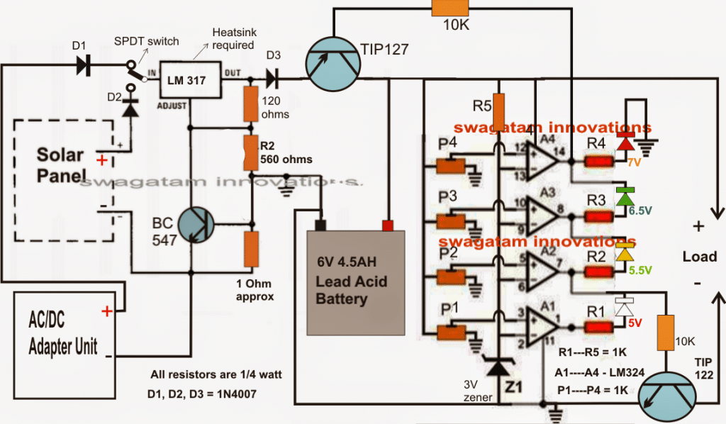
Hi swagtam, thanx for early reply. Can i put my 12v lion battery with it? Also pls let me know if i want only charging and discharging feature, can i remove A2 and A3 comparator from the circuit? What the use of bc547 connected with lm317? Is lm 317 necessary.. pls explain the circuit before making the project.
Thank you for your kind cooperation and time sharing..
Learned a lot from you and will continue as a student from you..
I beat no other site giv such a huge variety of circuit and explaining them individual queries…
Thanks Chandrashkhar, I am glad you are learning from this site!
You can remove A1, A3, and use A2, A4 as given., the BC547 and 1 ohm is used for controlling current at a fixed rate.
If your source supply is voltage controlled and current controlled then you can remove the LM317 circuit, and use the supply directly with the op amp transistor circuit
You can use 12v li-ion for charging with this circuit, just make sure to use a charging current that’s around 1/3rd of the battery Ah rating, and set the A4 preset to cut off at the full charge level, and A2 at the full discharge level.
Hi Swag,
I need to charge Li-Ion batteries of 1.5V 3000W.
Can I use this circuit for it, and if so, how to I adjust it?
Thanks.
Best Regards.
Nélio
Hi Neilio, which circuit do you wish to use, the last one?
Hi Swag,
I can use the last circuit.
To charge 1 or 2 1.5V 3000W Li-Ion Batteries.
Best Regards
Nelio
Hi Nelio, 3000 watts means 3000/1.5 = 2000Ah?? Are you sure about this?
Hi Swag,
Yes. I have 4 batteries of those but no charger.
And they both are Li-Ion, 1.5V and 3000W
Can I use the last circuit? Or do you other that can be suitable, preferebly with auto-power off or that the battery can be left in the charger after finish
A charger that can charge 1 or 2.
Best Regards.
Nélio
Thanks for the circuit update.
Best Regards.
You are welcome Nelio!!
Hi Swag.
Sorry, there was a misswriting in the text…. it’s not 3000W but 3000mW…. one single letter makes a diference…
Hi Nelio, you can try the following design
Initially keep the preset to ground level, now without any battery connected switch ON the input supplies. Green LED will switch ON ….Adjust the preset slowly until the green LED switches OFF an RED LED switches ON…you circuit is set now, and ready for use.
Hi Nelio, for a 2000 Ah Li-Ion batt, the charging current has to be 1000 amps, I don’t know regarding any relay or transistor that will handle 1000 amps. Do you have any idea?
Good day sir swag, can I used this circuit to charge 18650 battery. Thank you
Hi Rav, yes you can!
Thank you sir swag for very past answer. Sir can I also used this circuit to charge 2 to 4 pcs 18650 in parallel battery connection without modification? Thank you again sir
Hi Ravi, you can use the last design for charging 4 cells in parallel, you can also use the second last design by replacing the 2N2907 with TIP127
Thank you so much sir for answering my query. By the way this project is intened for backup power of my kitchen and shower room motion sensor and also for dark activated switch in the front of my house. Instead of using lead acid battery. Thank you again sir.
That sounds great Rav, thanks for the feedback!
Hello
Can we use this charger for Samsung 3.85 li-ion battery?(Full charge voltage is 4.4v)
yes you can use it for all types of batteries. Just make sure the input current is not above 50% of the battery Ah rating, and if you find the battery getting warm you can reduce the current further down
Hi. dear friend. thank you so much for sharing.
i modified your design and want to share here.
first of all, i used LM7805 voltage regulator for, Stable operation op-amp and relay. because even if i change the input voltage, the cut-off point changes in your design. Also, can not set clearly cut-off voltage because of battery voltage not stable as LM7805 output. So the 358 op-amp couldn’t work reliable.
Here is upgraded design. i separated voltage source of the op-amp and voltage reference of it. See my design is more stable and more reliable. thanks to you all. best regards.
https://i.postimg.cc/Zqc18v6t/Ekran-Al-nt-s.jpg
Hi, thank you for your interest, appreciate it. However the above explained design was written for USB operation which has a constant 5V already. Second, as explained in the article the preset adjustment is supposed to be done by supplying a stable 4.2V from a variable power supply, NOT by connecting a battery….
Please read the explanation carefully…
Hi, i updated the again. Ofcorse i added a few extra components. but now:
* Cut-off voltage setup more reliable.
* Auto Selects the working voltage, so dual mode auto switches to 5v input mode or 5.6v to 24v input mode. The 5.6v zener and relay auto switching to LM7805 voltage regulator to supply op-amp and charging relay even the input voltage over 5.6v to 24v.
* So we can charge 12v or 18v batteries with this design.
* Also we can charge car batteries because i used 6A diode on supply line.
# Hope if i can improve the project and helps everyone.
Best regards. Thanks.
https://i.postimg.cc/0Q5CgkDf/lion-charge.png
OK thank you very much for your efforts, appreciate it very much!
Hi Sir,
I tried the last circuit, encountered an issue, It’s charging the battery rated 3.7 li-ion. but, the green led keeps glowing, I’m not able to set cutoff voltage, with the method you mentioned. Can you please help here. I’m using 5v 1Ah mobile charger as input.
Hi Harpreet. did you follow the instructions mentioned in the article, without the battery connected. You will have to feed a 4.2V to the battery and then adjust the preset until green LED shuts off.
If you are unable to do this then the op amp or your circuit may be having some problems.
Sorry, can you give us the type of power source we should be use that will give us exact 4.2v while setting the cut off? Can I use 4.2v cellphone charger to set that? That is connecting 4.2v cellphone charger at the wall socket and the circuit?
You can use a LM317 adjustable regulator with 6V Dc input or you can use the following

The 10K pot can be adjusted to get 4.2V at the output whch can be used for setting up the op amp preset
Sir one resister is unnamed in the figure pls check and notify me…..
The LED resistor is also 1K
Hlo sir., in your circuit you have used 1uf 25v capacitor is it ceramic or electrolytic vif electrolytic what are its terminals ??
Also i have to ask that you video shows 4.5v charged battery after the cutout its dangerous for the battery what should be done?? Plss reply
Hello Naveen, the 1uF capacitor can be an electrolytic type.
The 4.5V is confusing for me also. It seems like some kind parasitic leakage and it is definitely not the Li-Ion voltage because the cut off is set at 4V so how can the Li-ion charge at 4.5V.
You can use a 5V relay instead as shown at the bottom of the post for ensuring a fail-proof result
Sir, I do the same thing you suggested,
I feed a fully charged battery (4.2 V) to the battery terminal without connecting to the power supply and set the preset to red LED glow. After that when I connected a discharged battery(3.9) to the circuit and connect the power supply of 5.1V 1Ah, the red LED glows which means its charged. What I’m doing wrong, please suggest.
Harpreet,
A fully charged battery will not give 4.2V, it may give 4V or even 3.9V, so this idea may not work…you will have to do it through a LM317 adjustable voltage regulator circuit…op amps are very accurate even 0.2V difference will give wrong results.
Also, after the setting up is done you must keep the battery connected and then switch ON the 5V input. And make sure you have a 1uF connected between pin2 and ground.
The green LED will glow momentarily when power is applied, which means the transistor will be allowed to switch ON and connect the battery with the supply and the green LED will lock until full charge is reached. But if the battery is fully charged the green LED will switch OFF and red will come ON.
Make sure the transistor are connected correctly….alternatively you may remove the green LED from the shown position and connect it in series with the 2N2907 base…this will give a clear idea whether the 2N2907 is switching ON or not when power is applied
Hi Sir,
I’m referring the 2nd last circuit, Where I’m able to set the cut-off voltage to 4.2V, but after connecting a battery no matter fully charged or discharged, the red led is on. I’m using KN2907A in place of 2N2907. Please suggest what to do.
You are right Sir, after connecting the battery directly it is merging voltage. As per you, transistor is not working properly. Please help to resolve this.
As if the circuit is working at 4.2V its should work on 5.1V 1A input. If the transistor needs to be replaced, what should be the correct one?
Harpreet, in that case you can try a new transistor like a 2N2907, TIP127 or 8550 etc. The best option according to me is using a 5V relay as shown in the last diagram. The relay contacts will allow full transfer of power to the battery and a perfect response.
Sir,
Thanks for the help. The circuit is running fine at a supply input of 4.2V after diode( where ). But when I connect the supply of 5.1V before the diode changes happen.
1 case:- supply voltage = 5.1V, Voltage across Diode = 4.3-4.5 V, (which is already higher than the cutoff voltages)
2. after connecting battery and power supply:- supply voltage = 5V, Voltage across Diode = 4.3-4.5 V, means it does not pull down the supply below 4.2V.
The transistor 2907 is working correctly at input supply of 4.2V
Harpreet, it means the battery is not accepting the current and dropping the voltage. Connect the battery directly to the supply line after the diode and check the voltage, this will prove whether the battery is pulling down the voltage or not. If it does, then the transistor is not working for sure.
Hi Harpreet, I’ll explain the simple working, then you can troubleshoot yourself.
The RED led will shut off and green will switch ON only if the input supply drops below the set 4.2V due to the battery discharge level.
When power is switched ON, regardless of the battery, the RED led must switch OFF for 1 second due to the 1uF capacitor which grounds the pin2 momentarily.
This ensures that the output of the opamp always starts with a logic HIGH, and turns ON the transistor so that the battery can get connected with the supply.
As soon as the battery gets connected it pulls down the supply below 4.2V, and this causes the opamp to lock to a HIGh output, with red led OFF and green ON.
This continues as long as the battery is charging, and reverts as soon as the battery reaches the 4.2V.
Now please check why your circuit is not responding to this function.
Connect an LED in series with the 2907 base to check whether it is switchin ON or not when power is applied
Thanks for your valuable response, I’ll try this.
One more question what is the difference between 2N2907 and KN2907. As my transistor is marked as KN2907. What should be the alternative to 2N2907 if not available.
Thanks a lot, You are doing great! if possible please share your contact details @ arpit.randhawa2612@gmail.com need to discuss few things of your interest.
Great!! Idea. But can you help us with one that we charge more li-ion battery like 12v 80ah
Glad you liked it, it can be implemented by upgrading the transistor rating, as shown at the bottom of this post:
https://www.homemade-circuits.com/charging-li-ion-battery-12v-car/
Good night illuminated Swag.
I set up your circuit with the lm358 and it is working very well. I only removed the current controls because it fits my purpose better.
Thank you for your teachings.
I hope to be able soon to be able to develop your most elaborate projects
Thank you Macelo,
I am glad it’s working, keep up the good work.
I want to give you another detail about the way the circuit i made works: I calibrated it at 10.1 V and it seems to charge normally (with a current flow of 28mA, green led on, red led off) only for the charging input 7.8 V or below (but the current flow decreases in the last case). What should be done?
Yes the current will decrease as the battery gets charged to the full level, that’s normal. But 28mA is too low. How much current did you use in the input supply??
You can remove Rx and the BC547 if the input current is below 1 amp
I’m sorry if you already received this comment, but i can’t see it above. I used more power supplies, one of 100mA, and other of 6.7A. I observed that the green led glows and the battery is charging for an charging input of aprox. 8.8 V (7.8 V); if this value increases even a bit, the red led glows. Maybe i didn’t set up correctly the charger (i applied an 10.1 V across the battery connections, whitout a charging input beeing applied; i also tried this with a charging input beeing applied). What is the relation between the charging input value and the output voltage of the circuit (on battery conections)?
I tested more the charger, but it doesn’t work like described in the article. Idon’t think the problem is the preset, i used a potentiometer and when aplling the 10.1 V on the charging input, the red led goes on and the voltage on the battery connections goes to 0 V(battery not conectet). Then, with this set up i connected the battery, then the power supply (the same 10.1 V), but the battery doesn’t charge, the red led is on. As i told you before, the red led goes off if i decrease the charging input voltage with some volts, but this voltage is not enought for fully charging the 8.4 V accumulator (there should be applied at the battery leads a voltage of 11.2 V). I mention that i used a BZX 3V0 zener diode, and the drop voltage on it is 2.11 V. How could i make my charger functional?
The circuit a basic comparator circuit and there’s nothing complex in it, and it’s fully functional.
A pot will not work here, because a pot can be very sensitive to movements.
Use only a preset.
I have updated the setting up procedure with new and easier explanation, please follow it and apply it exactly as explained. You can remove the current control stage (BC547 and RX) completely, to avoid confusions.
I tried the experiment with the bulb, when connected to the battery leads (whithout battery connected), it glowed more fade than connected to the power supply. But it seems something occured in the functioning of my circuit, because i tried to charge the 8.4 V/170mA battery with the folowing results:
– i setted up the circuit with a voltage of 10.1V;
– initialy, the power suplly voltage applied on charging input was 12.35 V;
-when battery connected, the voltage on it’s leads was 7.4 V;
-when i measured the voltage accros the power suplly, surprise! it decreased to 8.9 V, and the battery was charging with a current of aprox. 48mA (without current control);
– now is charging, but i don’t know if it will cut off correctly at the 10.1V.
Is this all right? Is the charger function correct?
Technically this is not correct, but if the op amp cuts off at 10.1V then it may be fine.
Apparently, this may be happening due to transistor collector/emitter resistance.
Keep a voltmeter connected and check whether it cuts off at 10.1 V or not. At 10.1V the pin2 voltage must get higher than pin3, which will make pin1 voltage zero, and cut off the transistor.
In this set up you can again try putting an LED in series with the transistor base to get a clear indication about the transistor conduction
Please modify as per this diagram, this one will show almost identical drop across the battery and the across the supply input
https://www.homemade-circuits.com/wp-content/uploads/2019/07/USB-Li-Ion-Charger-automatic.jpg
And how could i be sure my transistor conducts? (is in a good state).
Add a flashlight bulb in place of the battery and check its illumination, if the brightness is equal to when it is connected directly to supply, then it will mean your transistor is conducting fully.
If your existing transistor is giving problems you can make a Darlington pair using two 2N2222 together.
Or you can even try a MOSFET since your supply is at 9V, MoSFET will conduct a lot better than a BJT
…I’ll do some more experiments and let you know tomorrow, to make the transistor section more accurate.
I wiil answer your question with a question: In the circuit above, there is the charging input and the output on battery leads. When apllying a voltage on the charging input, battery connected, where the voltage should drop to the actual voltage of the baterry, on the charging input or on the battery leads? In my circuit, the voltage drops to the battery level on the battery leads, not on the charging input.
The transistor will short the battery negative with the ground, that’s how it will start charging, and when this happens the battery terminals get connected with the supply input…. now the supply input and the battery voltage merge together to become one, and their voltages level become one…in the video you can clearly this.
If you are having different voltage on battery terminals and supply input, then it means your transistor is not conducting, and the battery is not connecting with the ground line.
First, why did you modified the tipe of the transistor in the schematic above? (initially, when i started adding comments, in the schematic was a TIP 142, and now there is a TIP 122!)
You can use any Darlington transistor, it is not important, and will make no difference in the performance! I modified it because TIP142 was unnecessarily big and costly. You can even make a manual Darlington using BC547 and 2N2222 or any other similar combination.
I removed the green led from the base of the power transistor, i put it across pin1 of the IC and ground through a 1K series resistor, and it glows, but still fade. And the general problem get bigger: now, the battery is charging no matter the red led is on or off (the cut current does’t works anymore).
When you switch ON power does the supply drop to the battery level? Meaning if 10.1 V is the input does it drop to 8.4V?
I use a Li-ion battery of 2000mA. I completely removed the control current stage, but the problem is still there: when i connect the battery, then aplly the 5V, the red led indicates the battery is full, and does not charge. And by the way, at 5V the green led bairly glows (it ca’t be seen, it glows a bit at 10.1V). Can you give another sugestion? I also thank you again.
You can remove the green LED from the base and put it across pin1 of the IC and ground through a 1K series resistor, and see the results.
For 10V battery 5V will never work, if you use 5V then ue a 3.7V cell. or use 10.1V for the 10.1V battery.
for 2000mAh battery, you can try 500mA current
I’m sorry i boughter you again, Mr. Swagatam. I substituted the potentiometer with a trimmer, as i saw you used in the video (a don’t have a multiturn available), but the problem persists. As power suplly, i used more of them (even a nokia charger, 350 mA). The current control stage is so critical for the problem it occured? (i use a 12 Ohm Rx, enabling a 50mA current.) Another question is: according to the set up procedure, when the circuit is set up to 4.2 V, the charging process will stop when the battery reaches this voltage, no matter the voltage applied to the input of the circuit, is that right or not? If this sentence is correct, then my circuit doesn’t work like this, the input voltage is critical for the limit at the charging proces stops. I don’t really know what else to do, other component of the circuit could be damaged? (i.e. the power transistor.) Thank you again.
In the video you can clearly see how the system cuts off at the set 4.1 V, and it’s a very straightforward procedure. You can remove the current control stage just to check if it’s causing the issue. By the way 50 mA is a very low for any Li-Ion battery, which battery are you using?
The input actually does not matter if the current is low, because the input will drop to the battery discharged level until the cut-off threshold is reached.
Did you set the preset exactly as explained in the article? Because all op amp will sincerely follow the settings done across its input pins.
Yes you may not have adjusted preset accurately, that’s why it may be not cutting off at the right 10.1V…you can try using a multiturn preset for more accuracy.
When you switch ON the supply, the battery immediately connects with the supply through the MOSFET. Since the supply current is relatively lower it instantly sinks and becomes equal to the battery level, and then gradually rises as the battery gets charged until the supply level and the battery level become equal. Meaning suppose your battery discharge level is 3.5 V, and the supply input is 4.2 V, the 4.2 V will immediately drop to 3.5 V, and will begin rising slowly as the battery charges up to the full level.
For charging a 8.4 V/280mA accumulator, in the diagram indicated in the link would be necesarry a current control facility? After setting up the charger to cut of at 10.1 V, could i use a power supply of 12V? How many mA should have this power supply? Thank you verry much for your help.
…and the 2n2907 couldn’t be substituted with other transistor, i don’t have one available?
you can use TIP32, or 8550 or any other with above 1 amp current rating.
Wouldn’t be better to propose, please, if possible, a charger with current control facility? (I would like to use the charger for 8.4V, Ni-Mh accumulators, 280mA or higher, and i’d like to use a standard power supply for all of them).
Please see the last diagram in the following article, I have the post same diagram with a current control feature:
https://www.homemade-circuits.com/charging-li-ion-battery-12v-car/
Ni-Mh will also allow high current initial charging but will become quite warm…which is not good for the battery. Current control is not required as long as the battery is not warming up and stays at normal temperature below 35 degrees Celsius. You can use a supply lower than 50% of the mAh value of the battery, then current control won’t be required in my opinion.
I have done some more refinements in the design, and have checked it practically, also I’ll upload a video soon.
Here’s the correct diagram
https://www.homemade-circuits.com/wp-content/uploads/2019/07/USB-Li-Ion-Charger-automatic-1.jpg
…and the accumulator type is Ni-Mh.
I have a new question: i observed that the circuit presented in the video uses a 2n2222 transistor, and the schematic above has two transistors: a BC 457 and a TIP 142. What is the correct schematic? (i want to use it for charging a 8,4 V accumulator Ni-Mh, 280mAh, as i mentioned in another post).
The schematic presented in the article is more accurate.
Hi!
This is amazing. I just want to confirm;
For 1200mAH battery;
Rx = 0.6/1.2 = 5 ohm
For 2400mAH battery;
Rx = 0.6/2.4 = 0.25 ohm
If both the calculations are correct, please share the resistor color code to be used. If otherwise, please guide.
It’s not 5 ohms, it should be 0.5 ohms
use wire-wound resistors for both
And what will be the wattage of the resistor? Is there a bottom limit or any wattage can be used?
Multiply 0.6 with the current limit value, that will give you the wattage.
Hi Thanks, glad you liked it.
use 4.7 ohm instead of 5 Ohms: yellow, violet, black
For 0.25 ohms better to go for a wire wound resistor
pls
can
u send me a circuit diagram for liion battery 3000mah using lm324n
that is the only available one I can get
You can try the last circuit from this article:
https://www.homemade-circuits.com/simplest-safest-li-ion-battery-charger/
Why do you need LM324?
I tried the second circuit with exact part and its not working.!
there’s only 1 circuit on this page, which second circuit are you referring t?
is there one like this that uses 555 timer?
IC 555 will not work below 4.5V
Hi Swag,
Nice circuit…. Can I use it for charging a 7.4V Li-Ion battery? If so, what changes do I need to do?
Best Regards.
Nélio
Thanks Neilio, you can use the very same circuit with no modifications, except the preset threshold setting.
Hi Swag,
Só I need to replace the Zener and ajust the 10K?
Best Regards,
Nélio Abreu
Hi Nelio, No, the zener will not change. I meant to say that only the cut off threshold adjustment using the preset will need to be done as per the battery full charge specifications. I think it should be 8.4V for your case!
Hello sir,
I must thank you for all your patience and kindness, my question is, will I use 6watts 6v solar panel on this circuit? Again what exactly should i use to power the circuit while adjusting the preset to get that 4.2v since you said we should remove battery ? Am very sorry if my question is out of point, am just a newbie.
Thanks.
Thanks for the quick response, but the second question is, should I use 6watts 6v solar panel on the circuit? Can it work?
Yes you can use 6V 6 watt panel for the mentioned battery.
Hello Ani, the process will be the same, you will have to apply an external 4.2V across the supply line, and adjust the perset such that the RED LEd just switches ON and green LED switches OFF
Hi Swag,
Can I leave the battery connected to the charger circuit after full?
Best Regards,
Nélio Abreu
Hi Swag,
One last Question….
Can I charge Li-Po batteries with it, or is it only for Li-Ion?
Best Regards
NA
Hi Nelio, you can charge any battery with this circuit. You can charge Li-ion, Lipo, lead acid, all will charge safely with this circuit. Just make sure to select Rx appropriately.
Hi Nelio, yes no problems, you can do it!
Please how can I have a design of 5v solar panel, lithium battery (3.7v or any you recommend), and to charge Smart phone.
The circuit mentioned above is the best circuit that you can get for charging a li-ion cell, you can apply it without any concerns.
Please, what’s the wattage of LED light bulb in phones and likely lumens. Thanks
sorry, I do not have any idea about it.
Thanks a lot.
The transistor 2N2222 is a NPN …the correct transistor is a PNP like BC557…
With a NPN, as showed, the current max is 10mA with a PNP up to 100mA …
The schematic is wrong
You seriously need to learn electronics…I can help you understand if you want.
Sir, can I use above circuit to charge a spare li-ion mobile battery using mobile charger with 5v and 2A output (as written on charger, another charger noted as 5v and 1 A)???
Also I don’t have device to set the value of preset ?
Can u suggest some fixed value of resistor??
Nitin, preset is the easiest device to set, calculating fixed resistor practically can be very tedious, so you will have to use a preset here for the adjustments.
yes any 5V input source will work. as long as the current is not higher than the Ah level of the battery
Sir, I have li-ion mobile battery 3.7v . Can I directly connect it to 5v mobile chargers’ terminal to charge it or it requires to connect a diode??
Nitin, If you are not using an automatic cut off circuit then you may have to include two 1N4007 diodes in series, so that the 5V drops to a safe 3.9V level.
A single diode will also work, but in that case you will have to monitor the charging voltage and switch it off as soon as 4.1V is reached.
I’ve got a question that Google and YouTube hasn’t been able to answer. Is there a way of wiring 3, 18650 cells to get two simultaneous voltages. I’m trying to get 3.7 volts and 11.1 volts from the same three cell bank. Something like a series and parallel, probably with some diodes, type of setup maybe? Or would it be better to just go with series and run a step down converter for the 3.7 volt side of my project?
Thanks in advance,
Maintenance Mike
Sir,
First appreciate for your efforts for this compact simple charger. Sir can I use 18650 battery for safe charging by this circuit? The module available from China little expensive.
Thank you Siso, yes you can use 18650 battery with this charger. Connect the battery first and then switch ON the input supply.
nothing complex about it..you will have to connect them in series, the end terminals will allow you to get 11.1V, while the 3.7V can be extracted from the bottom most battery which has its negative acting as the ground…I hope you go it.
Awesome, why didn’t I think of that. And also, thanks for the quick response. I see a portable stereo headphone amp / usb power bank in my near future. Woo whooo!
Glad you liked my suggestion, wish you all the best…
Hello sir, am requesting a circuit from you: a 12 to 5v 2A or 2.5A usb Charger circuit with for charging phone from 12v source
Hi Solomon, you can try the following concept and slightly modify the coil and the R8/R9 values as per your required specifications
https://www.homemade-circuits.com/5v-pwm-solar-battery-charger-circuit/
Sir good afternoon! can I charge 2 li ion batts. in parallel? is it better to use lm 321?
Hi Jindro, you can use two Li-ion in parallel with this charger. LM321 is good, but 741 will also work equally well…
No sir I didnt connect zener diod but without it I recieve 2 volt output and cellphone dont charges,please help me ,I really need this circuit.I want to build a circuit that connects between mobile charger and mmobile and cuts off charging when it fully charges.
connect the zener diode as I advised in my previous comment and check again….at any instant only one LEd should be ON, two cannot be ON, because the 741 output will be either “high” or “low” at any instant, never both..
If I do this it will work correctly? because I measured output volyage andit was 2 volts.
2V where? are you getting it after the zener connection?
after connecting the zener diode only one LED will be ON.
I made this circuit but both LEDs are illuminate
connect a zener diode in series with the pin#6 of the IC, between the LED junction and pin#6, see example here
https://www.homemade-circuits.com/make-6v-4ah-automatic-battery-charger/
i have 3.7 volt battery.. can i input 3.7 volt in this circuit.
yes you can!
is this only limited to 5V output?
upto 18V
Sir, can i charge 18650 with this circuit ? Tks
Should i change ic 741 with LM358 or not sir ? Tks a lot
Yes you can
Hi there. I want to make my 18650battery into 11.1v . Do you have a balance circuit on it?
what is your exact requirement? a 3.3V to 11V converter or 11v to 3.3V charger?….please clarify
Hello sir. Can u help me. Can I set a current to get 1ampere using the circuit u give and what component should I change to get 5volt 1ampere.
Then, I have a generator which can generate 20-50volt 400mA.if I apply the supply as a input for the circuit.can it work? Please help me sir.This for my assignment. Can u email the answer at irsyadkanashii@gmail.com.
Hello Putera, for converting 20 to 50V 400mA into 5V 1amp you may have to employ a buck converter, and then the output from this buck converter could be applied to the above mentioned circuit.
Hello, sir. We are having difficulties in making this circuit work. We do not know if we are having trouble with the variable resistor. Also, can we use the digital voltmeter to the "To Cell Phone" instead of a discharged battery to know if a "battery" would charge since the voltage reading, if we are right, will increase in the DVM.
Hello feathers, the circuit above is very simple and does not require any complex setting up procedures…please mention the problem specifically i'll try to help.
sorry I could not correctly understand your second question regarding usunf DVM with cell phone, how can that be possible?? please clarify
Hello Sir,
I am trying to make the circuit for mobile to mobile charging, How can I modify this circuit to charge another mobile or which circuit I should use sir. Mobile A as a charger and Mobile B as a client. Both are having micro-usb connector at their ends. I tried using OTG (On to Go) connector but it is not working in all the device and current rate is also very low.
Hope for your positive and quick reply sir..
Thank you..
Hello Shubham, the above circuit won't be required for mobile to mobile charging application….a boost converter circuit could be tried for the purpose, and to implement it successfully the charger mobile battery must be rated higher in terms of its AH rating.
the supply from the charger mobile will go to the boost converter and the output from the boost converter to the client mobile….that's all would be needed.
Good day sir, I want to make a circuit with automatic cutoff when battery reached fully charge and need the output with 5v and 1A. I use samsung li-ion battery with 3.7v and 1000mAh. For the input i use samsung adapter with 5v and 2A.
Is it ok for me to use this circuit?
Is need to me to add regulator IC7805/LM368 in this circuit? Or no need because of the input 5v?
And lasty, i am not understand how to setting preset by connecting into the battery.
I hope you reply this comment. I really need your help sir.
Thank you sir.
Faruqi, you can use the mentioned adapter for charging your battery.
7805 will not be required if the adapter is rated at 5V
use a 1 ohm 1 watt resistor for the current limiting resistor.
the setting up procedure is already explained in the article, please read it carefully. you will need a power supply adjusted at 4.2V for the setting up and this must supply must be fed from the battery side.
Hello sir,
I am an electric and electronics final year student. My final year thesis is portable smart solar battery charger for Li-ion battery(3.7V/1200mAh) from solar panel 5V/1000mAh which have LEDs indicator, overvoltage and overcurrent protection, etc. I was hoping sir can help me on how to make a solar charger smart. I mean both theory and PCB circuit.
That is what I have thought about developing so far sir. But i am not sure about the complexity of it therefore i am open to any new suggestion to improve this design.
Thank you for your quick feedback and I truly appreciate your assistance sir. Have a great day sir.
nguyenthe toan, you can try the following design and see how it performs:
https://www.homemade-circuits.com/2015/10/smart-emergency-lamp-circuit-with.html
Thank you sir i will try both circuits, Good night
Who many battery 3.7v battery 1000ma to ? This circuit supportable upto battery amps
Sir, i want to made a powerbank for my smartphon where i will used 6V 5.5Ah lead acid battery as a source and output should be 500mA please help me, Is any modification needed in this circuit?
try reducing the series limiting resistor value to 2 ohm or to 1ohm and see the response, and make sure the 7805 is mounted on a large heatsink.
you can also try a PWM in conjunction with a 7805 and see how it works. You can use the following circuit for feeding the PWMs to the 7805 input:
https://www.homemade-circuits.com/2012/01/how-to-build-simple-pwm-controlled-dc.html
i already done this by 7805 and 7806 voltage regulator but there was some problem charge become very slow and the below 500mAh batteries are not charged, phon just on and off automatically. one more qus, Is pulse is needed to good recharge the Li-ion battery?
Debanjan, the current is not important, it's the voltage that should be compatible with the phone's charging voltage spec. You can use a 7805 IC circuit with your battery for implementing it as explained here:
https://www.homemade-circuits.com/2012/03/how-to-make-simple-dc-to-dc-cell-phone.html
Who many input voltage and amps charging battery 3.7v 1000ma to 3000ma? What Mobile Phone charger used this circuit? How adjustable preset voltage? please answer this question
you can use 1amp to 3 amp charging current for the mentioned batts respectively….use the mobile charger which are used normally for smart phones, the circuit explanation is already given in the article above.
This is nice circuit but is the charging current is fixed at 200ma? How can i increase that to 500MA or 1A?? Im planning to put this as a charger of powerbank rated 3.7V
thanks, you can upgrade the circuit to any desired current level by changing the 3 ohm resistor through the following formula
Resistor = 0.7/max charging current
Thanks sir… i m waiting for that…!!!
And sir give me favor to inform me on this email id…
Irfan45@msn.com
Irfan, I have published it here:
https://www.homemade-circuits.com/2015/11/make-this-power-bank-circuit-using-37v.html
Dear sir i want to make a power bank using 3.7v rechargable cells. Can u help me to make a circuit for power bank. I want the output 5v 2amp… thanks in advance
Dear Irfan, I'll to include the article soon in my blog…
Dear sir, what is the purpose of transistor BC547, and resistor of 3 ohms? Whether is't enough op-ams pin of 4?
Another question: is this circuit for charging super capacitor for 2.7 V voltage?
Dear Linas, BC547 and 3 ohms is for limiting current to the battery (constant current)
2.7V super capacitor can be directly charged from a 3.7V li-ion battery (from cell phone) through a 1N4007 diode.
I need some help regarding this :
What would be actual current at emitter of 2907 as in thread you have mentioned it should be 4.30v. I am using simple cell phone charger with 5v output.
To set preset I have followed your instruction and connected the charger (5v) – 1n7001 – 1k resistance to make it 4.30v am I doing it in wrong way?
if 5v input is set to 4.30v what will be prest values should be at pin 2 of 741 and pin3 ?
I have designed and tested last corrected circuit diagram connected battery of 3.20v (approximately 40% discharged) turned on input and checked with voltmeter nor the LED is turned on not the battery is being charged!
Is that possible my IC is damaged? as during scolding heat issue or once i have accidentally touched both pin 3 and 2!
Please help me I am extremely committed myself to do this as a challenge !
I have all parts in extra quantity with me ! I can re-design if some chip is required to update.
…please do everything as explained above, if you do anything against this then the circuit will not respond.
If you have used a 1K resistor in series with the 5V input then the battery will never charge because the resistor will drop the entire current going to the battery.
use a single 1N4007 diode with the 5V supply and connect this supply from the battery side first.
Next adjust the preset such that the red LED just shuts off.
now seal the preset.
remove the 5V supply and the diode, and replace it with any battery which may require charging.
connect the 5V supply with the diode from the other side that is from the USB side and check the procedures….
Hello, sir,
If you don't mind, can you guide me to add a piezo buzzer in the second circuit? I need a warning sound when the battery fully charged.
Thank you in advance.
Hello Devi,
you can add it across pin6 of the IC and ground line of the circuit
Our source is from a heat harvester where we will boost its voltage to 5v. It depends to the amount of heat wether what current will be produced. Do we need to have current regulator in order to use this circuit? And also will this circuit work for our purpose? I'm really having a hard time to look for a good circuit for protection to the battery.
current should be 2 to 3 times more than the charging current only then the voltage will step-up and charge the battery….otherwise the voltage will keep dropping
I did exactly in the 2nd circuit. I used a 1.5v batterry and used a booster to have 5v and used it as a source.
the circuits are intended for genuine 5V supply…a modified input will not do….what's the current level of your 1.5 input source??
a penlight cell will not work, the 1.5v AH needs to be thrice that of the cell phone battery AH level….
Thank you so much Sir Swagatam. I tried the circuit but I only got 3.5v output where I read that it has to be 4.4v. I measured it in the negative side of the diode and to the positive.
Pinky, which circuit did you try?….please make the last circuit in the above article, the first one might not work correctly….
Hi Sir. Thank you for linking me here. Is it possible to output a higher current to charge the battery? And also is there another circuit to modify the output current from the battery to the load. For example we want to charge the battery by 1a and output 500ma. In our study, we arebusing the battery as a powerbank. Could that be possible for a 1860R 3.75v 24000mah battery? Thanks in advance!
Hi Pinky, you can replace the 2N2907 with a TIP127 and increase the current handling capacity of the circuit upto 3amps.
If the voltage of the powerbank is compatible with the load, then the current factor can be ignored…you can use any magnitude of current it won't affect the load or the powerbank…just make sure the voltage specs are matching
if the voltage specs do not match in that case you employ the following concept for restricting the current to a recommended level:
https://www.homemade-circuits.com/2013/06/universal-high-watt-led-current-limiter.html
The 3 ohm resistor on the below circuit is 1/2W too or it doesn't matters?
multiply 0.6 with the intended charging current and it will tell you regarding the wattage of the resistor
Hi, I've got a nokia 3V7/1Ah battery. What is important if I want to choose an alternative transistor of 2N2907? The IC Max and the HFe, right?
yes the current (Ic) rating is important, make sure it's rated at above 1amp…hFe is not so important
sir, what should i do to increase the current to 1 – 1.5 Amps so as to increase the charging speed ??
reduce the value of the 3 ohm resistor proportionately, this will allow more current to the output
Hi bro,
In the second diagram above the usb input and battery output places are opposite according to first diagram, does it works? please clear my doubt. Nice blog though.
yes bro, the positions are correctly shown in the second diagram and will work as explained….but remember to connect the battery first and then switch ON the USB supply in order to enable the circuit respond correctly
Tried the circuit with LM358, the led glows very little but never flashes, can you please provide the circuit with LM358.
Thank You.
the LED is not supposed to flash, it will stay solid when the over charge is reached.
reduce the LED series resistor to 470 ohms or 220 ohms and check the response.
hello everyone,
i try to simulate this circuit in NI multisim but i found that the LED doesnt glow. please give me sollution.
thank you…
I have a 3.7v 20700mah battery pack (Lithium ion cells) I require a charging circuit that will deliver 2.5amps / 3amps from a 5v 3amp charger. Your assistance would be appreciated as using the current charging circuit 4.4v 1amp takes too long to charge. Your help you'd be appreciated
You are welcome Shane, yes it can done using a 555 boost converter circuit but the output wattage will never exceed the input wattage
wattage refers to V x I specs of the battery
so if the input 3.7 x 3 = 11.1 watts
the output would become 5V @ 11/5 = 2.2amps
Thank you very much, Swagatam, is it possible to build a circuit that will step up 3.7v to 5v @ 3Amp/h?
connect the 5V source to the battery pack through a 6A4 diode, this will immediately make the 5V 3amp charger compatible with your battery since the diode will drop the excess 0.7V and feed the correc4.3V for the batt pack.
If you intend to have an automatic cut off when the battery gets fully charged you can opt for the last circuit shown in the above article.
Thanks Sir Ji
विक्रम संवत 2072 भारतीय नववर्ष और नवरात्री के पावन पर्व पर हार्दिक मंगल शुभकामनाएं |
Thanks Amit, wish you the same.
Hello Sir , what is the use of 1N4148 diode, can I replace it with 1N4007 diode
Hi Amit, yes you can do it
Hi , Sir
I have two 3.7 v battery and i connected it in series so it will be 7.4v so how can i use this circuit
thanx in advance…
Hi Kalarav,
you can use the last circuit from above for your application without any change, just the input voltage will need to be increased from 5V to 10V
Hello Sir , can i use bc557 instaed of 2n2907pnp for above 2nd circuit, above 2nd circuit is suitable to charge nokia 3.7v900mah battery
Thanks in Advance
Hello Amit,
BC557 will burn due to high charging current requirement of the cell phone, you can try TIP127 or BD140 etc instead
BC557 is used in the first diagram, BC547 is used in the last diagram, so it is BC547 as per the last diagram
yes 0.466 or 0.5 ohms is correct.
Hello Nurv, LM358 will be more appropriate since it will operate even with voltages as low as 3V, IC 741 is not specified for working below 4.5V
good day Nurve, yes you can try the last circuit, calculate the 3 ohm resistor as per your battery AH rating with this formula
R = 0.7/batt AH
sir i am making a digital clock using 8051 micro controller no other ic is used in that schematic any other ic is needed for giving pulse? shopkeeper said me that it might require 1 more ic for pulse
yes it could be so!
i think it needs to be programmed
…OK sorry, it seems you do require another clock timer IC for it….a DS12C887 Real Time Clock may be
Rushi, I think external clock is not required, it should be coded in the chip itself…
sir, http://www.circuitdiagram.org/images/adjustable-power-supply-circuit-7805.gif
this circuit can really give 12v output if that input is 9v? I am confused in that circuit 7805 is used and how can be the output can be varied upto 12v giving 9v input?
Rushi, that's a rubbish circuit, 7805 is a fixed regulator IC, it cannot be used like a variable regulator.
sir i have a resistive touch pad it has 4 pins. how can i use it like mouse for pc. please give me a schematic.
Good day sir. I’m having issues in charging the 3.7 V 9900 mAh LiON battery. It can’t be fully charged even I left it charging for about 4-5 hours. Then I measured the terminal voltage of the battery which is about 4.04 V only. But it should be 4.2V right?
Hi Angelo,
If you are using 4.2V DC as the full charge voltage, then it should reach 4.2V, if not then your battery could be having problems. However, if you are using 4 V then if the battery settles at around 4V then it is absolutely fine…even at 4V the charging can be considered optimal and it will ensure longer life for the battery and enhance charge discharge cycles.
okay, thanks for your reply.
Rushi, it looks complex to me, presently I do not have any idea regarding it…
Sir please send me a schematic of a circuit which will boost battery voltage to 5v
Thanks
Rushi, you can try the following circuit
https://www.homemade-circuits.com/2012/10/1-watt-led-driver-using-joule-thief.html
Sir i saw all your schematics related to li-ion battery charging and one doubt came in my mind which circuit will be best for charging li-ion battery through usb?
any circuit that cuts off the supply at the specified full charge threshold of the cell can be used.
Sir, I want a 32-0-32 transformer but I cant get it so can you send me a circuit schematic of power supply to power this circuit
https://drive.google.com/file/d/0B3aDGghiCQzzWWpZQUJJcHRZX00/edit?usp=sharing
you can try this circuit:
https://www.homemade-circuits.com/2012/03/how-to-make-simple-12-v-1-amp-switch.html
adjust R6 and R7 for getting the required 45V, 7805 stage can be removed
I want a circuit that will convert or reduce 230vac to 45vdc
12-0-12v will give 18V RMS, you can use it with a lower amp output….boosting this further won't be possible…
Sir, I cant get more than 12-0-12 transformer
Rushi, use a 24-0-24V transformer, after full bridge rectification and filtration the output will become well over 32-0-32V
Hi,
I will be using 5V 1.5A adapter to power this,how can i increase output current to 1A instead of 200mA
Hi, use a different resistor in place of the shown 3 ohm….for 1 amp, the calculations will be as follows:
0.6/1 = 0.6 ohms…so use a 0.6 ohm resistor in place of 3 ohm for allowing 1 amps….wattage of the resistor will be 0.6 x 1 = 0.6 watts. a 1 watt can be used.
do you take classes???
I want to learn from you.
Sorry, taking special classes will not be possible for me, you can learn by posting comments and getting replies from me here.
sir, usb negative and ground wire in this circuit are separate??
Thank you for your help.
Regards.
………your diagram is correct!
a preset is always a better choice, fixed resistors will need to be calculated and fixed extremely accurately.
yes lipo, Nicd batts can also be charged with the above set up
okay okay now I Got It sorry
and we can charge any battery with this circuit– Li-Polymer ni-Cad ,etc????
sir i knw voltage divider but I want to replace 10k pot and to replace i want formula to find value of resistances between pin3 and gnd and pin3 and vcc
to get a specific voltage for different batteries.
https://drive.google.com/file/d/0B3aDGghiCQzzamJVbWRkdDlQbjg/edit?usp=sharing
Use R1 any arbitrarily selected value….keep R2 blank and select output just above the pin2 reference voltage. that is just above 1.9V
Rushi, you can go to this site and find the values:
http://www.raltron.com/cust/tools/voltage_divider.asp
input V will be your 12v, 2.4v or 3.7v etc.
output V will go to the pin3
R1 and R2 will be across positive and ground in the circuit with the junction going to the pin3.
Your link above is not opening, change the status to "sharing"
Sir, will you give me the formula to find the output voltage in this circuit so ican replace 10k pot and put a keys for charging 1.2v, 2.4v,3.7,…….batteries
See this circuit diagram I have edited your circuit schematic as per my need. Tell me is this circuit correct or not.
https://docs.google.com/file/d/0B3aDGghiCQzzamJVbWRkdDlQbjg/edit
Thank you Sir
could be at the rate of 1C meaning at the same rate that's printed on the battery,
the resistor value could be found with the following formula
0.6/AH,
or simply, the BC547 and the 3ohm can be completely removed….current limiting is not so crucial
how many amps is needed to charge a 3.7v li-ion battery?
and tell me value of resistor (3ohm in circuit) so i can get 2a output current
….through the 3 ohm resistor, do exactly as shown in the diagram..
USB negative is connected with the circuit and the battery negative.
Sir, what is the function of 10k variable resistor in this circuit?
apply an external 4.2V DC from the battery side in the last diagram, adjust the preset such that the LED just lights up…that's all the circuit set now.
a DC/DC booster circuit can be seen in the following link
2.bp.blogspot.com/-rQ2R8YaFF8c/U372ZScaZdI/AAAAAAAAG8o/nL51vjRHAkk/s1600/speed+breaker+boost+circuit.png
Since I am making a power bank, will you upload a circuit schematic of dc-dc booster? which will convert 3.7v li-on battery to 5v or greater (I will use 7805 to make it 5v) and output current of 2a
how to set it??
It's for setting the full charge cut-off level of the battery.
Dear Sir,
Manu thanks to you for this circuit. I have one question sir. I think you have used the OP-AMP as Schmitt Trigger. But one thing I didn't understand for the LED to blink, terminal 3 of the OP-AMP should go above 1.8V and for that to happen current through the 10k pot. should rise. So, my question is will the current through the Li-ion battery drop automatically increaing the current through the 10k pot?
you are welcome!
My heartiest thanks to you sir.
Dear Kallol,
The voltage at pin3 will drop and will be below the reference level at pin2 while the discharged battery is being charged.
This will create a low at pin6 which will keep the LEd and the PNP latched ON for supplying the charging voltage to the batt.
As the batt becomes fully charged, pin3 voltage will rise and at some of time cross pin2 potential, reverting the pin6 output to high, switching off the PNP and the charging voltage.
Sir. We tried assemble your circuit but even the led is not turned on. Do you have any tips on how should we troubleshoot the circuit?
Turning the preset to and fro should cause the LED to switch ON/OFF at some specific point on the preset, if this is not happening means there's something incorrect in your circuit connections.
Thanks a lot sir. Your replies have always been abrupt. 🙂
Thanks for guiding.
Thanks a lot sir.
And I also wanted to confirm..I need 4.2 volts and 1 amp from the charging circuit. Will it deliver so? ( I have the 5v 2 amp input for the charging circuit input).
Suggest me if any change required sir.
how to set up to 3A, i need to charger 4 Pararel 3.7 Battery..?
thanks.
Hello sir, please can I use this circuit to charge 5 parallel connected 3.7v li-ion batteries? Thanks
yes you can, just make sure all the cells are good, and the transistor is upgraded to higher rating, along with the current limit value….
for 1amp output replace the 3 ohm resistor with a 0.6 ohms, 1 watt resistor, rest will be as is.
Sir..actually I have some laptop batteries….from which I have spared the 18650 cells that are present inside the battery.
I use the 18650 for many battery operated projects….but I dun have any way to recharge them..
Don't have much money to buy one from market…so I thought of asking u to please help me in the making of a 18650, 3.7 volts cell charger.
Anirudh, you can try the circuit that's shown in the above article, it will suit your application.
Hi sir. Thanks for helping me with the last project.
Now I was considering another project . Actually I want to make a "18650" cell charger.
Could you help me in making one?
Hi Anirudh,
please provide more details about the project.
please sir, can i use only resistor to drive a 1 watt white LED from an AC source? If yes, what should be the resistance of the resistor and if no, what should i include in it?
330 – 3.3/.3 = 1089 ohms or a 1k resistor will work
wattage will be around 100 watts.
it's better to use a cell phone charger instead., you can use a 3 ohm/2watt resistor with it
so what can i opt for?? sir y it doesnt charge ? plz explain…..
capapcitive power supplies produce lower currents and higher voltages,both are not suitable for lead acid batteries.
Rohith, please refer to the first diagram in this article, you should do it in this way:
https://www.homemade-circuits.com/2011/12/how-to-make-efficient-led-emergency.html
Sir as a beginner i would like to know what is a capacitive power supply?
also why cant it be used for lead acid battery?
Thanks in advance…
sir i have charged that way, its been charging quite ok… but actually on that emergency ckt board a capacitor & resistor & some others were present , in which two things gone C & R their original values i have told u & u said 10ohm is ok but any other substitutes for C ?
use a 0-6V transformer power supply with a bridge rectifier and 2200uF/25V filter capacitor, capacitive power supply will not work
Please sir, i could'nt get the uA741 8-pin op-amp. Can i replace it with LM358 or LM324 by using one of its op-amp train, since, the 358 is a dual op-amp, while 324 is quad nand op-amp?
Yes you can do it, no issues.
Sir not from this blog, iam having a 6v 4ah emergency , in which the capacitor was gone firstly (2.2mF 250v) & i replaced, the result was an explosion ,by mistake i took an electrolytic one…. 8ohm 5w R was burned too. now i got a non electrolytic one(0.24mFJ 800v 1200v.dc 50khz) instead of 8ohm R i got 10 ohm 5w can i use it safely….???
yes 0.24uF/800v will work but will not charge the 6v/4ah battery. 10 ohm will do for 8 ohms
by the way i have answered your email.
Also iam having two types of batt 3.7v & 3.6v (digi cam) li ion. can i charge ? mA may be different for both.
sir i have sent a mail regarding the substitutes for C & R in emergency lamp, havent got any reply… plz check…
you can charge any battery by using the above circuit, but the current limiting should be set appropriately.
Which emergency light are you referring to, is it from this blog?
As i/p v is fixed to 5v i hope i can use 7805s ckt with just ic , diode, 2 caps without current limiting Resistor?? as that of DC to DC charger & provide it to this..??
Sir,
Please check the output pin of the ic358 out.thats the reason majority of readers not working properly not over to the zener diode reduce 10k to 1k for working properly.
Thank you
Thank you very much Sison, I have corrected the diagram now. It was actually modified from my earlier IC 741 version for 12V charging, and later a LM358 was added in it, and I forgot to change the output pin details.
By the way the 10K for the zener is fine and won’t cause problems…with 10K the Iz would be 0.5mA, sufficient to switch ON the zener.
if the li-ion is within 1ah and 2 ah a 7805 can be used and without the current limiting stage.
Hi sir,
the circuit is a reliable one ie charges to 100%? No exceptions in i/p current ? i/p v is 5…. can be used for any ampereage li ion batt?
Hi Rohith,
any amperage can be used provided the input also is capable of supplying that much of current and the resistor is correctly calculated.
Ok. Thank you sir! Let me try and see what the current will be like
hello everybody
I have 12v 7.2A battery and I wanna charge my phone via usb port without using computer
I have an usb cable and want to use it in this project
how can I charge my phone directly from this battery please ??
hello Swagatam
would you check this circuit please ??
imageshack.com/a/img30/8392/pgcl.jpg
my phone doesn't recognize it although I test the out voltage is 5.07 !!!
thanks so much 🙂
..the 7805 will require a heatsink.
use a 7805 IC for dropping the 12V to 5V, then feed the 5v to the cellphone via the above circuit
What if i connect a Dickson charge pump voltage doubler at the output of the charger so that it can produce two times the voltage(ie 11v) and then i will use a voltage divider network to reduce the 11v to 7v, will it work normal? Or better still i will use LM317T to reduce the 11v to 7v
It should be able to produce the required charging current also, which should be about 1/10th of the battery AH, then it could work
Ok. No problems. Please sir, i have a nokia charger(China made charger) that can produce 5.5v and 800ma. Can i use this charger to charge a 6v, 4.5Ah rechargeable battery? If yes, for how many hours can it charge it at a full rate?
J-boy, no you cannot charge with a lower voltage source, you will need a 7V input for charging a 6V batt.
Thanks alot sir. I am grateful. Please sir i sent you an email at "hitman2008@live.in"
thanks j-boy,
sharing phone no wouldn't be possible, I think this is what you had requested in the mail.
We can chat here freely.
Please sir, i have three questions about the above circuit. When this circuit is charging the cellphone battery, will the LED be flashing? Or is it only when the battery is full that it starts flashing? Secondly, what is the required input voltage and current of this circuit? And finally, what is its output voltage and current?
how to set max of current up to 2A ?
Hello J-boy,
As mentioned in the article the LED will be lit continuously (solid) while the cell is being charged and will start flashing when the cell is fully charged.
Input should be 5V fixed, you can use a LM317 circuit at the input for allowing higher voltages.
You can remove the 22k resistor entirely for getting a good flashing effect at the full charge threshold.
output voltage will be around 4.4V, current 200mA max