In this post I have explained two methods of connecting batteries in parallel. The first one below deals with changeover circuit using SPDT switches to charge multiple batteries individually or collectively. These may be connected in parallel using a single battery charger and through a manual SPDT changeover switch bank.
The seconds design talks about how batteries could charged together with cross discharge.
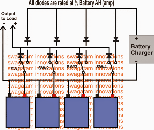
1) Parallel Batteries with Changeover Relay
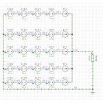
Referring to the following diagram, the configuration shows four batteries with their negatives connected together to form a common negative rail.
The positives are all terminated individually to the poles of four discretely attached SPDT switches.
The one of the two changeover contacts of the SPDT switches are appropriately connected with the output load while the others with the battery charger positive.
All the above terminations are made via separate rectifier diodes, each for output and input positives of the batteries.
The discussed parallel battery charger with changeover circuit using SPDT switches allows the user with options to connect as many number of batteries as desired in the array, and also to select which battery or how many batteries need be integrated with the charging system, or with the output, or both.
The diodes in the system make sure that the batteries don't interact with each other producing a cross discharge across each other, and ensures a step wise charging and discharging for the same.
2) Connecting Batteries in Parallel without Cross Discharge
The second method described below of connecting batteries in parallel not only charges and discharges them uniformly across common sources, it also completely isolates them inhibiting any cross-discharging possibility. The idea was requested by Mr. Ron.
Technical Specifications
I found your site and it is most impressive.
I hope that you may have a solution to the following problem. I have two 12 volt batteries in my caravan and for charging or providing power to appliances, they are wired in parallel.
I have been told that if one battery was to drop a cell then the healthy one will attempt to charge the bad one due to variation in voltage.
The battery with the dropped cell is useless and in the scenario I gave, the healthy battery will not remain healthy for very long.
Is there a solution that keeps the batteries in parallel for charging and discharge in normal use, but separates them in a fault situation? Would appreciate any advice that you can give. Ron
Circuit Operation
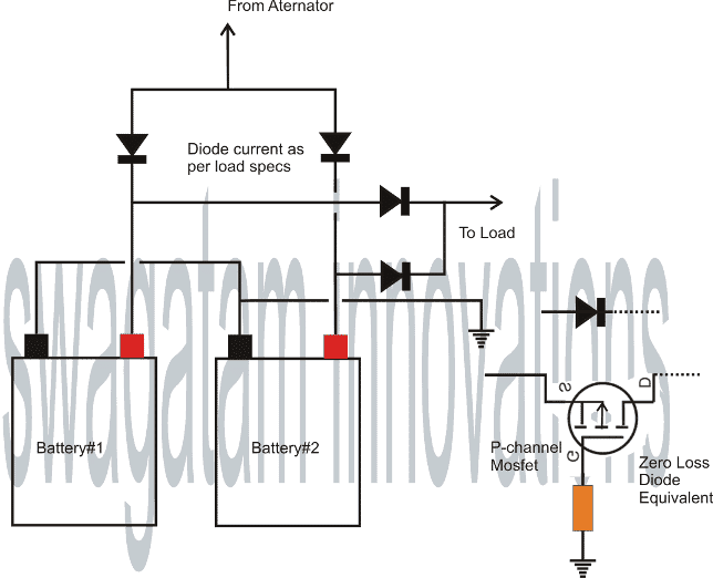
The shown method of connecting batteries in parallel without cross discharge is very simple and involves the use a few diodes.
The diodes effectively block the inter links between the batteries preventing any possibility of cross discharge, yet allows them to charge from a common source and discharge uniformly across a common load.
Although the diodes provide an easy alternative for the above actions, it drops around 0.7V across itself.
The above drop might look insignificant, however during critical situations the issue could make a lot of difference.
In order to make the circuit more efficient a mosfet equivalent circuit could be wired up as shown, replacing each of the diodes.
The resistor could be anything between 50 and 470 ohms, the mosfets should be a P-channel type with voltage and current rating slightly above the max specified limits.
The mosfet option provides identical features like diodes with an exception that it won't drop anything critical.
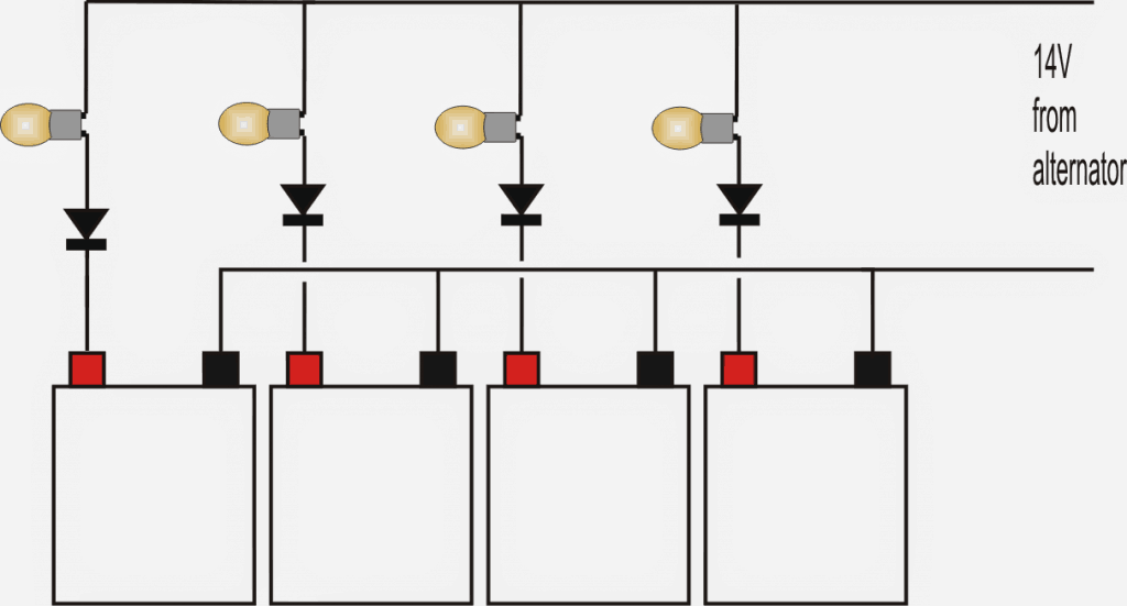
Charging lead acid batteries in parallel with simple current control indicator feature:
Important Feedback and Questions from the Readers regarding how to connect batteries in parallel.
Dear Swag,
Thank you for this useful circuit>
Please, tell me if its suitable for 115 AH batteries or not
Thanks
Reply:
Dear Sayad,
Yes the concept is suitable for all batteries.
For 115ah battery, 20 amp diodes or mosfets would be needed.
Thank you for making this information available on the web.
I have two questions about your design.
1. Is the mosfet you specify an enhancement or depletion-type? Or will either work in this parallel battery charging concept?
2. It is unclear to me how a three element/lead mosfet it actually wired into the battery cable between the batteries. I understand the assignment of the leads (Gate, Source and Drain) though I am also unclear how to identify which of the outer is which).
I guess there is more than one question there. Anyway, I have had three batteries charging in parallel without protection several years ago, and one of them failed, and destroyed the other two. I now charge six batteries but with separate chargers, and would like to bring that down to using only the charge controller from my newly installed solar panels.
Thank you.
Reply:
Thank you for asking this question!!
It is a P mosfet (depletion) which is supposed to be ON as long as its source voltage is higher than its gate voltage.
all the gates are wired with the common negative (-) of the batteries via individual resistors, the sources are wired with the respective battery positives, and the drains are connected together with the load positive.
I have assumed that this would effectively replicate a zero loss diode.
Another Feedback
Sir help me.
I have made an automatic battery charger circuit using opamp 741
Everything was done perfect. But the problem occurs during charging. I have used a battery monitor circuit using ICLM3914 indicating 10.5 V to 13.5 volt( fully charged ) by 10 LEDs.
I have caliberated the circuit to be cut off charging in 14.5 V and starts again in 11.5 V using a variable Dc supply.
When i am connecting the battery, no problem us there. Battery monitor working properly. But when i am switching on the dc power source ( which is a 15 V 5 A ac/dc adapter ) the monitor level changes and suddently indicating the higher battery voltage ( sometimes indicating battery is fully charged eventhough it is not ). ALSO THE RELAY ACTIVATES AND CHARGING IS STOPPED..... This problem was found constant by testing with a 11.5 V battery and 12.6 V battery. So will you please help me in solving this.
Solution:
Hi Arun,
Your power supply current should be 1/10th of the battery Ah, please confirm this first.
Alternatively connect the power supply directly to the battery and check the voltage at the battery terminals, it should drop to the discharged level of the battery, confirm this too.
Another remedy could be to connect a 100uF cap across base/ground of the transistor.
The above suggestions should fix the problem
I am also having another problem that when i am connecting the parallel config. of the batteries (as in this blog ) to the charging station, the relay alternatively switched on and off making the all LEDs in the battery monitor blinking simultaneusly. But no such disturbance is seen while using a single battery. Then what i have to do? No mistake occured in connecting diodes. Everything perfect. Since this only includes battery charging, i have only employed the section of alternator in this blog
The above circuit is very basic, it only consists of diodes so that the battery which has the lowest charge begins charging first, then the next lower charged one and so on....the presence of diodes should not cause any interference to the charger according to me....the problem could be with your charger circuit....try using a high grade regulated power supply and then check the results.


Questions & Answers
12v agm batteries in a boat. All are AGM 105 ah. One battery is used for starting and is charged via engine alternator.
The other two batteries are house batteries connected in parallel providing 210 ah. for running accessories. I have an automatic adjustable dual battery isolator used to recharge the house batteries. When I store the boat inside garage I wish to install external separate charger maintainers with very low amperage (5amp or less), one charger for the starting battery and the second charger on the house batteries. Can this be done without the separate battery chargers being in conflict with each other?
Any advice is appreciated.
Thankyou,
Rod R
Thank you for the question.
Since you want the charger to be used only as a maintainer, with low current, a single battery charger can be used for maintaining both the batteries through separate diodes, as illustrated in the above article.
Let me know if you have any further doubts or questions.
Be carefull with unintended current-paths when using a FET to replace a diode.
a FET is a voltage-controlled *resistor*.
a FET also has an intrinsic diode between the Drain & Source.
By chance anyone like to redraw diagram 1 such that it outputs in series? The idea is to use four (recovered)12 volt lifepo4 batteries to power an ebike with 48 volt but be able to charge in parallel @ 12volt. I’ve read to use four separate chargers but switches or relays and diodes seem cheaper. Any advice or a.point in the right direction?
Converting the first diagram to work in series looks difficult. No ideas!
Thanks for the reply, In my mind outputting to series just involves adding relays to be able to break the parallel connections between batteries (used for charging) and bond the series connections(to ride) as the bank will only be doing one or the other at a time. Working through the possibilities of a stuck relay is where I get overwhelmed. Perhaps a big switch would be better? Thanks for the diagram as that is one half of my imaginary circuit.
Your suggestion sounds interesting! I may check it to verify in my free time. The relay is getting stuck, is it due to fusing of the contacts? In that case you might require a bigger and more powerful relays.
Hi Sir, I’m working with led emergency lamp using 4v,2Ah SLA battery two connected in parallel. When I set the charging voltage at the recommended 4.7v,the charging current is only around 250mA even if the charger is rated as 2amp. But this will take more time for full charging of the two parallel batteries. Two batteries in parallel will make the ah capacity at 400mA as far as I know. But the charger is not providing the same value current. So is it a good idea to increase the charging voltage to more than the recommended 4.7v till the charging current is around 400mA or is there any other solution for this prblm? And again sir, I connected the two batteries without the diodes as you mentioned. Is it safe to do so? Pls give ur valuable reply..
Hi Binoj,
If the full charge voltage is 4.7V for the two batteries then you must never increase the voltage above this level. If you are sure that the charger is rated at 2 amps and still the two batteries in parallel are not consuming 400 mA then it is not the fault of the charger, it is the fault of the batteries. However, still do not force the batteries to consume more current by increasing the voltage above their full charge levels, that could harm the batteries. There seems to be no solution to the problem because we must allow the batteries to decide how much current they want to charge fully. In fact using 2 amp current source for 400 mA batteries is dangerous and you must have some kind of current controller installed, because if suddenly batteries starts consuming more than 400 ma then that can be very bad for the batteries.
Connecting separate diodes ensures that the batteries charging function do not interact with each other, but not using the diodes is also fine, it will not cause any harm to parallel batteries.
Good discussion. I wanted to avoid cross discharge. thanks.
Also I need to clarify this, according to some studies, up to 30% percent of power is lost when charging a battery. Therefore I add the 30% when determining the charging current for the battery, I hope am right about this?
Power is usually wasted through heat dissipation, and this will depend on the level of the source voltage, if it’s much higher than the battery full charge level then the dissipation will be higher, and vice versa.
Ok thanks, but you can also help on how I can build the separate current controller to monitor each battery.
You can try one of these circuits:
https://www.homemade-circuits.com/universal-high-watt-led-current-limiter/
For this design, do you need to add up the battery Amps which is connected in parallel to decide the charging Current? or is the current for a single battery enough to charge up the batteries?
Here is what I mean, when batteries are connected in parallel, the Amps add up, so in this charging circuit will the total Amps of the four batteries be required for calculating the charging current?
Or will the Amps for just one battery be required?
Thanks am waiting for your answer.
Since the batts are in parallel the amps will add up naturally, and the charging current will have to be around 10% of the total Ah rating of the parallel batteries. If for example there are 5 nos of 100 Ah batteries, the minimum charging current will need to be 50 amps
However, having a separate current controller for each battery is recommended, because some batteries may charge earlier than the others causing an over-current on other batteries.
Hi
Thanks for all
Question regarding to your comment : even when one among batteries is Full Charged before others, normally its acceptance of Current will be reduced naturally and that will result in hi resistance to current making natural for other batteries that are not yet Full charged to be favoured . Am I wrong ?
Yes that’s correct!