Among the different existing inverter topologies, the full bridge or the H-bridge inverter topology is considered to be the most efficient and effective. Configuring a full bridge topology could involve too many criticality, however with the advent of full bridge driver ICs these have now become one of the simplest inverters one can build.
What's a Full-Bridge Topology
A full bridge inverter also called an H-bridge inverter, is the most efficient inverter topology which work two wire transformers for delivering the required push-pull oscillating current into the primary. This avoids the use of a 3-wire center tapped transformer which are not very efficient due to their twice the amount of primary winding than a 2-wire transformer
This feature allows the use of smaller transformers and get more power outputs at the same time.Today due to the easy availability of full bridge driver ICs things have become utterly simple and making a full bridge inverter circuit at home has become a kids play.
Here I have explained a full bridge inverter circuit using the full bridge driver IC IRS2453(1)D from International Rectifiers.
The mentioned chip is an outstanding full bridge driver IC as it single handedly takes care of all the major criticality involved with H-bridge topologies through its advanced in-built circuitry.
The assembler simply needs to connect a few handful of components externally for achieving a full fledged, working H-bridge inverter.
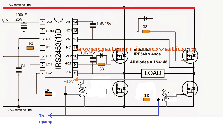
The simplicity of the design is evident from the diagram shown below:
Circuit Operation
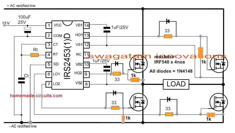
NOTE: Please join the SD pin of the IC with the ground line, if it is not used for the shut down operation.
Pin14 and pin10 are the high side floating supply voltage pinouts of the IC. The 1uF capacitors effectively keep these crucial pinouts a shade higher than the drain voltages of the corresponding mosfets ensuring that the mosfet source potential stays lower than the gate potential for the required conduction of the mosfets.
The gate resistors suppress drain/source surge possibility by preventing sudden conduction of the mosfets.
The diodes across the gate resistors are introduced for quick discharging of the internal gate/drain capacitors during their non-conduction periods for ensuring optimal response from the devices.
The IC IRS2453(1)D is also featured with an in-built oscillator, meaning no external oscillator stage would be required with this chip.
Just a couple of external passive components take care of the frequency for driving the inverter.
Rt and Ct can be calculated for getting the intending 50Hz or 60 Hz frequency outputs over the mosfets.
Important Calculations
Frequency Calculation for IRS2453 Oscillator
The IRS2453 chip uses external components Rt and Ct to set the PWM frequency.
Formula:
f = 1 / (1.453 × Rt × Ct)
- Where:
- f = Switching frequency (Hz)
- Rt = Timing resistor (ohms)
- Ct = Timing capacitor (farads)
Example Calculation:
Let us Assume Rt = 33 kΩ = 33 × 10³ Ω, Ct = 1 µF = 1 × 10⁻⁶ F:
f = 1 / (1.453 × (33 × 10³) × (1 × 10⁻⁶))
f = 1 / (1.453 × 33 × 10⁻³)
f ≈ 20.9 kHz
Thus the switching frequency is approximately 20.9 kHz. So you can adjust Rt and Ct to modify the frequency as needed.
Gate Resistors
The 33ohm resistors at the MOSFET gates limit the inrush current during switching and dampen oscillations.
Power Dissipation in Gate Resistors:
Pgate = Qg × Vgate × f
- Where:
- Qg = Gate charge of the MOSFET (63 nC for IRF540)
- Vgate = Gate drive voltage (10V)
- f = Switching frequency (20.9 kHz)
Substituting values:
Pgate = 63 × 10⁻⁹ × 10 × 20.9 × 10³
Pgate ≈ 0.013 W
Each gate resistor dissipates approximately 13 mW, which is negligible.
Power MOSFET Ratings (IRF540)
Drain-Source Voltage (VDS):
The MOSFETs must withstand the full rectified supply voltage. For a 15V input, VDS(max) must be higher than 15V. The IRF540 has a VDS(max) of 100V, which is adequate.
Current Handling (ID):
Each MOSFET handles half the load current:
ID = Iload / 2
Ensure ID(max) (33A for IRF540) exceeds this value.
Reverse Gate Diodes
The 1N4148 diodes ensures instant gate capacitance discharge for the MOSFETs, which ensures efficient switching response from the MOSFETs.
Reverse Recovery Time:
The recovery time for 1N4148 is 4ns, suitable for high-frequency switching.
Power Dissipation:
Pdiode = Vf × Iload
Where Vf = Forward voltage of the diode (0.7V for 1N4148).
Load Power
The load determines the current through the MOSFETs and resistors.
Load Current (Iload):
Iload = Pload / Vsupply
For Pload = 50 W and Vsupply = 15V:
Iload = 50 / 15 = 3.33 A
Power Dissipation in MOSFETs:
PMOSFET = ID² × RDS(on)
For IRF540, RDS(on) = 0.044 Ω:
PMOSFET = (3.33 / 2)² × 0.044 = 0.122 W per MOSFET.
Capacitor Selection
Input Capacitor (100 µF/25V):
Filters the rectified AC and smooths the supply voltage. The ripple current rating should exceed the load current (Iload).
Bootstrap Capacitors (1 µF/25V):
These provide gate drive voltage for the high-side MOSFETs. Ensure the value can handle the gate charge (Qg) of the MOSFETs.
High Voltage Feature
Another interesting feature of this IC is its ability to handle very high voltages upto 600V making it perfectly applicable for transformeless inverters or compact ferrite inverter circuits.
As can be seen in the given diagram, if an externally accessible 330V DC is applied across the "+/- AC rectified lines", the configuration instantly becomes a transformerless inverter wherein any intended load can be connected directly across the points marked as "load".
Alternatively if an ordinary step-down transformer is used, the primary winding can be connected across the points marked as "load". In this case the "+AC rectified line" can be joined with pin#1 of the IC and terminated commonly to the battery (+) of the inverter.
If a battery higher than 15V is used, the "+AC rectified line" should be connected directly with the battery positive while pin#1 should be applied with a stepped down regulated 12V from the battery source using IC 7812.
Although the below shown design looks too easy to construct, the layout requires some strict guidelines to be followed, you may refer to the post for ensuring correct protection measures for proposed simple full bridge inverter circuit.
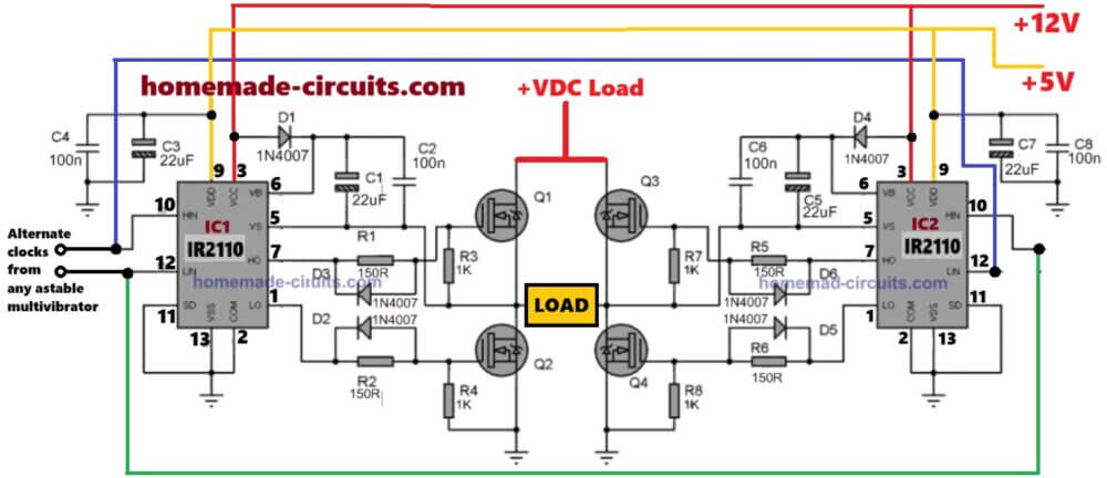
Simple H-Bridge or Full Bridge Inverter using two Half-Bridge IC IR2110
Parts List
| Component | Value / Part Number | Description |
|---|---|---|
| IC1, IC2 | IR2110 | High and Low Side MOSFET Driver IC |
| Q1, Q2, Q3, Q4 | IRF540 or Similar | N-channel MOSFETs |
| D1, D2, D3, D4 | 1N4007 | General-purpose rectifier diodes (for bootstrap circuit protection) |
| C1, C2 | 100nF (0.1µF) | Ceramic capacitor (decoupling for IR2110) |
| C3, C4, C5, C6, C7, C8 | 22µF / 25V | Electrolytic capacitors (bootstrap and power supply stabilization) |
| R1, R2, R3, R4 | 150Ω / 0.25W | Gate resistors for MOSFETs |
| R5, R6, R7, R8 | 1KΩ / 0.25W | Pull-down resistors for MOSFET gates |
| VCC | +12V | Power supply for IR2110 |
| Logic Supply | +5V | Logic supply for control signals |
| Load Supply | VDC Load | Main DC power for the load |
| Clock Input | From Astable Multivibrator | External alternating PWM signal source |
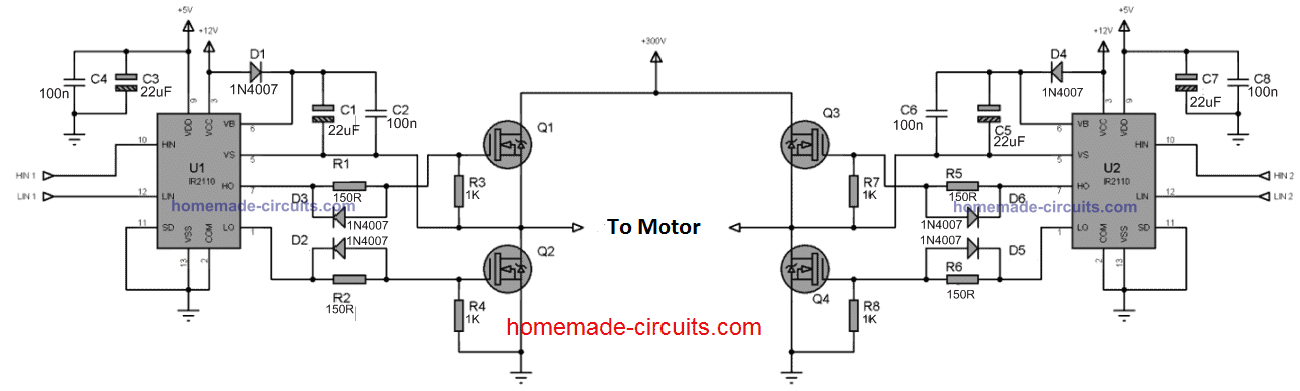
The diagram above shows how to implement an effective full bridge square wave inverter design using a couple of half bridge ICs IR2110.
The ICs are full fledged half bridge drivers equipped with the required bootstrapping capacitor network for driving the high side mosfets, and a dead-time feature to ensure 100% safety for the mosfet conduction.
The ICs work by alternately switching the Q1/Q2 and Q3/Q4 mosfets in tandem, such that at any occasion when Q1 is ON, Q2 and Q3 are completely switched OF and vice versa.
The IC is able to create the above precise switching in response to the timed signals at their HIN and LIN inputs.
These four inputs needs to be triggered to ensure that at any instant HIN1 and LIN2 are switched ON simultaneously while HIN2 and LIN1 are switched OFF, and vice versa. This is done at twice the rate of the inverter output frequency. Meaning if the inverter output is required to be 50Hz, the HIN/LIN inputs should be oscillated at 100Hz rate and so on.
Oscillator Circuit
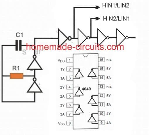
This is an oscillator circuit which is optimized for triggering the HIN/LIN inputs of the above explained full-bridge inverter circuit.
A single 4049 IC is used for generating the required frequency and also for isolating the alternating input feeds for the inverter ICs.
C1 and R1 determine the frequency required for oscillating the half bridge devices and could be calculated using the following formula:
f = 1 /1.2RC
Alternatively, the values could be achieved through some trial and error.
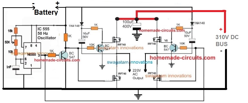
Discrete Full Bridge Inverter using Transistor
So far we have studied a full bridge inverter topologies using specialized ICs, however the same could be built using discrete parts such transistors and capacitors, and without depending on ICs.
A simple diagram can be seen below:



Questions & Answers
thanks in “Discrete Full Bridge Inverter using Transistor”
BC547❗ change to >360v Bjt : MJE13001 or MJE13003 [very Emportant, not Explode ]
1N4148 Change to >390v Fast Diode such FR107 , UF4006 ,UF4007[for safety ]
two 15v zener needs in parallel with Gate-Source High side MOSFETs
Please remember it is just a basic test circuit setup and modifications can be done as required depending on the application…
Snubber for MOSFETs can be added, that’s fine, and change 1k to 100 ohm or 50 ohm…and change 1N4148 to BA159
hi sir am currently working on class d amplifier using sg3525 ic I couldn’t find any half or full bridge driver ic to be connected to the gates of the output MOSFETs.so I ask can I build a descrete one out of transistors just like the one you describe above?
Hi Abubakar,
yes you can try the BJT based design, however for guaranteed and accurate results, I would strongly recommend the IC IR2110 based full bridge circuit. Let me know if you have any further doubts…
educate me .. u is using an N Mosfet for high side switching
finally after reading all that is required to use P channel and N channel for high side switching , from many data sheets yes you have educated me,
much thanks
regards
Br
Thank you, I am glad it helped you to understand the concepts better…please keep up the good work…
Hie sir, I want to make a 24v Fullbridge inverter , 12 mosfets , 3per channel , can I use transistor level shifters to drive the mosfets instead of drivers?
Hi Majaha,
Basic level shifters will not work for N-channel h-bridge without complex circuitry, so specialized driver ICs will be required, since they can make H-bridge designs very simple and reliable, so driver ICs are recommended.
Some induction furnace designs have the problem that the MOSFET or EGBT burns out quickly and its protection is very weak. I want a design that allows the EGBT to work with the drive.
Hello, I just tried to replicate your circuit in Qspice, but it’s not working. Have you ever simulated it in Qspice or LTspice, or did you just build it directly?
I’ve built a half-bridge with only one driver before, and that worked. Now I’m trying to convert the DC-DC with 30V operating voltage into a DC-AC. Any tips for me?
Hey, the IR2110 circuit is 100% tested and a practically working design.
Make sure the HIN and LIN of the two ICs are correctly swapped….meaning the HIN of one IC joins with the LIN of the other IC and vice versa…
Thank you for your feedback. The HIN and LIN of the two ICs are connected correctly. I can see that the SPWM is correctly inverted in the four inputs. The problem is with the outputs and the voltage at the load. Yesterday, I also sent you an email with the file I created in Qspice. Have you looked at it? Thank you in advance!
Hi, It is not possible for me to troubleshoot a simulator result…however if you build and test it practically and explain me the issue, then I can try troubleshooting it, but not a simulator result…
sorry I did not find any email of your..
pls can you send me a 24v low battery protection circuit diagram for my inverter using sg3524 ic. or using relay to disconnect the supply voltage from entering into the voltage regulator lm7812. with explanation pls
Bright, you can use the following circuit and connect the pin#6 of the opamp with pin#10 of the SG3525:
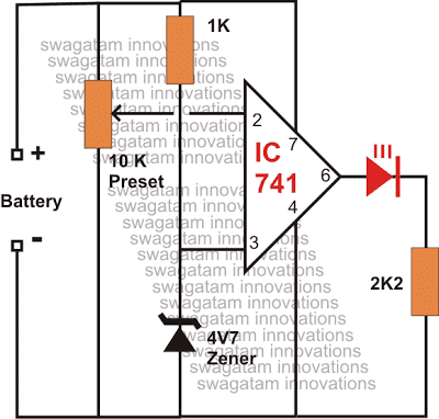
Please replace the 741 with one opamp from IC LM358 and Adjust the preset appropriately to set the cut off point of the Ic.
I power the circuit with 48v battery it blow my high side MOSFET pls what bootstrap capacitor to use because I use 50v/10uf which work on my 24v battery before but now on 48 my MOSFET blow pls help
Your bootstrap capacitor is OK, according to me, even for 48V….
I think you must use snubbers for the MOSFETs, and always use a series bulb initially while testing an confirming a newly built design:
https://www.homemade-circuits.com/explained-snubber-circuit-for-mosfet-h-bridge/
pls what are the things to change if I want to make this ir2110 h-bridge inverter work on a 48v battery. should I change the boost capacitor to what pls.
I made this H-bridge circuit with two ir2110, sg3524 as my oscillator and my battery voltage is 25.6v but when I put my multimeter at the load side of the mosfet for transformer, I was getting 28.0v stable, when I set the preset of sg3524 the voltage comes down to 24.2v to 21.0v and the voltage was fauctuating. pls what do I do. I want to use a transformer from a 24v 2kva inverter.
If your meter is set to read AC, then the voltage looks OK to me, since the AC across the load side will read same as the battery voltage. If the meter is set for DC then you must see around 13V DC on your meter for a 25V battery….
If you want to be 100% sure then you may have to use an oscilloscope to check the waveform across the various points on your inverter.
Right now, you can connect and small transformer across the load side of the MOSFETs and check whether the transformer generates the 220V AC or not…
Nothing needs to be changed except the drain side voltage for the MOSFFETs, except the bootstrap 1uF capacitor voltage, which should be 100V rated. Also consider putting snubbers across each mosfets as explained below:
https://www.homemade-circuits.com/explained-snubber-circuit-for-mosfet-h-bridge/
Pls one of my MOSFET gate resistor of 33kohms spiol can I replace it with 10 ohms resistor in my inverter since it is only one
Why did you use a 33k initially, was there any specific reason? For high frequency operation of a MOSFET through a logic gate, the resistor can be a low value such as 10 ohms. So if your MOSFET gate is connected to some logic IC then yes you can use a 10 ohm series resistor.
pls can I still use 10uf/50,v as boost cap on a 48v to 220v inverter
Yes, because the circuit is still operating with 12V DC only,….the MOSFET side is operating with 48V
pls I want to build 24v inverter h-bridge with ir2110 MOSFET gate driver which value of capacitor to choose as bootstrap capacitor. can I choose 50v/47uf or 50v/10uf
10uF/50V should be quite enough.
El tl494 para que sirve
tl494 is an oscillator IC.
Gracias por ayudarme a mejorar las experiencia en electrónica
Porque los diodos de salida del inversores se calientan
which diodes are you referring to exactly?
hello sir i hope you good,, i have talk with you about full h-bridge solar inverter 5.5kw and volatge from the solar is 490v and i am using SPW47N60C3 mosfet and 10 mosfet on each channel all mosfets i will use 40 mosfets ….10 on each channel i will use 2 IR2110 ic and cd4047 for pwm for 2 IR2110 ic to drive mosfets to make it full h-bridge
i have a question and thanks you for your time.
how much current the circuit need for ics to feed gate mosfets without any problem and what is the best voltage?
Thank you Sayed,
The MOSFET gates are high impedance inputs so the current does not matter, the gates can work with microamperes also, so nothing to worry about the current. The best voltage is 12V.
The ICs might need 5 to 10mA for operating correctly.
pls can any h-bridge pure sine wave 12v inverter transformer work with this circuit
pls if I want to build this inverter to work on a 48v battery, with ir2110 driver can I use a zener/resistor to regulate the 48v from the battery to 12v and 5v to power the ic/ir2110
Yes, you can use zener/resistor for stepping down the 48V to 12V at the VCC pin of the IC…
Yes, any two wire primary/secondary side transformer will work…
okay i want ask you again and i am sorry for taking from you time.sir
i will make circut without transformer to feed the ics and gates of mosfets
12v 150 ma it will handle the gates and ics?
question two the gates takes power from the 2 IR2110 ics and cd4047 right?
No problem Sayed,
Yes 12V 150mA will more than sufficient for the ICs and the MOSFET gates.
Your second question is also correct. However remember that the HIN pin of one IR2110 IC must connect with the LIN pin of the other IR2110 IC, and vice versa.
make full h-bridge solar inverter 5kw and i am using irfp460 amd 10 mosfet on each channel all mosfets i will use 40 mosfets ….10 on each channel i will use 2 IR2110 ic to drive mosfets to make it full h-bridge
i have some questions and thanks you for your time.
1. can i use tl494 as an oscillator for 50hz for 2 ic ir2110?
2. what is the best resistor to add on gates mosfets on each channel?
Yes, those MOSFETs can be used, provided your solar input voltage is above 200V DC.
TL494 cannot be used to generate 50Hz frequency. You can use 4060 iC instead, or the one explained in the above article.
For 50Hz you can use any gate resistor between 10 ohm and 50 ohm 1/4 watt.
thanks for your answer sir,
but in ic4060 can i add feedback to adjust votlage automaticaly ??
and i asking i should add resisiter on pwm signals coming from ic4060 to 2ic ir2110 like mosfets gates ?
and thanks for your time sir
Hi Rony, yes a feedback can be added to a 4060 based inverter circuit, but a 4060 will require another NPN BJT for inverting the output for the HIN, LIN inputs.
The outputs from the 4060 IC to the HIN, LIN inputs of the H-bridge will not require any resistors, they can be connected directly.
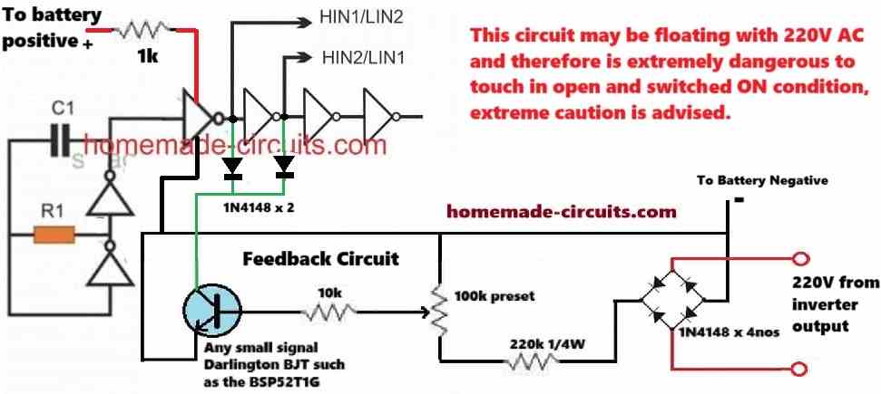
However I think the oscillator using the 4049 IC, as given in the article, is even better since it won’t require an external NPN BJT, and a feedback can also be added to this 4049 circuit.
okay so the 4049 IC is better and i can add feedback for this inverter without any problem?
and if you have a circuit of ic4049 and how add feedback i will be greatfull and hanks for your time
You can configure the feedback in the following manner:
hello if i use cd4047 ic instead of cd4049 ic is ok?
i mean cd 4047 is ok like cd4049?
and thanks for your support and help me and other beginers
Yes, that’s a good choice, you can use the two outputs of the 4047 IC to feed the HIN, LIN inputs of the H-bridge IC.
okay sir you answer me with this (Rony, The SPW47N60C3 VDS is rated at 650V, so if your inverter output is rated to work with a voltage above 150V and below 400V then this MOSFET will be good, you can use it.)
if i used solar panals around 450 volatge at open circuit it willl work fine or i will face problem?
i made a reply on old message because thr last messge did not give me option to reply and thanks again
Yes, if your inverter is rated to work between 400V and 500V then the 650V VDS rated MOSFET will be good enough. You can go ahead with it, no problems!
The comment threads can handle a maximum of 10 replies, after 10 replies the reply option will not be available, then you have to create a new thread…
hello sir welcome again and thanks for your great advices
i have told you At the beginning of the conversation((make full h-bridge solar inverter 5kw and i am using irfp460 amd 10 mosfet on each channel all mosfets))
can i use SPW47N60C3 mosfet instead of irfp460 in the circuit??
Rony, The SPW47N60C3 VDS is rated at 650V, so if your inverter output is rated to work with a voltage above 150V and below 400V then this MOSFET will be good, you can use it.
okay sir thanks alot
but for confirm as you know i will add feedback to adjut voltage automatic so it will working well and i should not add another NPN BJT for inverting the output for the HIN, LIN inputs ??
Hi Rony,
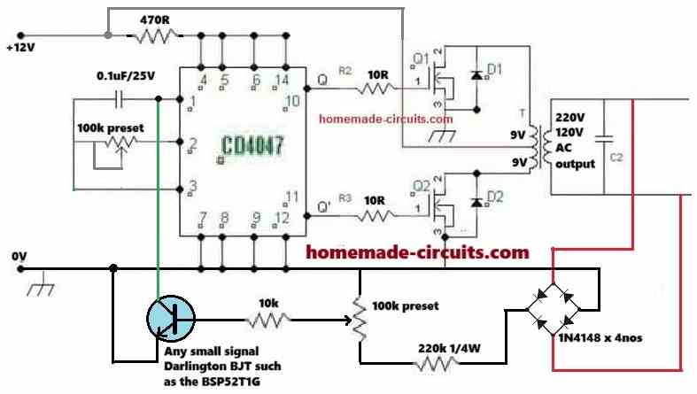
you can add the feedback to the 4047 IC in the following manner:
There’s no need of another NPN BJJT for the HIN, LIN inputs, you can directly connect the two outputs from pin#10 and pin#11 of the 4047 IC to feed the HIN, LIN inputs of the H-bridge iCs.
hello i want to ask you sir , i want to make full h-bridge solar inverter 5kw and i am using irfp460 amd 10 mosfet on each channel all mosfets i will use 40 mosfets ….10 on each channel i will use 2 IR2110 ic to drive mosfets to make it full h-bridge i want to ask you it will work 100% duty cycle right and it is okay?
Yes, that will work, but the duty cycle cannot be 100%, it should lower than 50%.
but i need duty cycle be 100% because voltage of solar 400v i need to get full power can you suggest i will use feed back on it
Yes you will get around 100% power output from the inverter output. By 50% duty cycle I mean to say the output from the ICs will 50% ON and 50% OFF, as we have in a square waveform.
okay sir , are you have any video or article can help me to add feedback on this circuit and make frequency 50hz
Sure, for feedback control you can implement the second concept which I have explained in the following article:
https://www.homemade-circuits.com/load-independentoutput-corrected/
50 Hz frequency will be controlled by the input oscillator, feeding the square waves to the IR2110 ICs.
Good morning Sir,
Thank you for the reply,
If I add short-circuit protection using comparator lm358 then what will be the value of shunt resistor (current sensing resistor) for 3kw load and the value of vds and IDs of MOSFET for pussing the ground to the circuit ?
Good Morning Rinku,
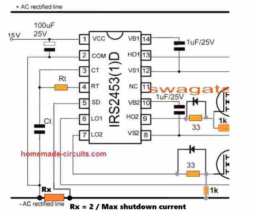
You can configure the shutdown pin SD of the IC in the following manner:
Remember, this will latch up the circuit, meaning if an over-current is detected the IC will shutdown permanently, until power is switched OFF and ON again.
Good morning Sir,
For the scenario of IRS2453 the high side HO1 &HO2 gives 50 hz square wave and we punching 2khz or higher through LO1 &LO2 ,does this make sign wave as both the high side switch received 50Hz. If we give one high side HO2 with 2kHz and LO1 with 50Hz and vice versa then proper punching happens to create sign wave .plz give insight on this as I have seen esg002 card works on this principle
Sir, my simple question is we are giving only low side spwm signal so does it make signwave properly as my mosfet blasts.plz help
Regards
Rinku
Good Morning Rinku,
Applying SPWM to the high-side MOSFETs, which require bootstrapping for proper operation, could be problematic.
The low-side MOSFETs, however, are simpler to control with SPWM because they connect directly to ground. By controlling the low-side MOSFETs with SPWM, the load current will follow the same pattern.
To make sine wave you just need to chop the low side MOSFETs.
In your design are you following the principles explained in the following article:
https://www.homemade-circuits.com/mosfet-protection-basics-explained-is/
If you chop the low side MOSFETs with SPWM the output will also SPWM because the low side is in series with the high side MOSFET.
Remember for iron core transformer the SPWM frequency must not exceed 300Hz.
Dear Sir,
I am using this circuit for transformer less inverter so I have to give 800Hz to 2500Hz spwm signal to the low side MOSFET, Your opinion plz
Rinku, which circuit exactly, please provide the link?
I have a ready made foreign H- bridge MOSFET board that has no gate reverse diode on it, can I drive it with this circuit and ic
You can add the reverse diodes to the gate resistors of the board for maximum safety and efficiency…
Good if P1 Remove but Series with R1 for lower current in pin 7 of 555 IC.
Please try with low frequency first, 300 Hz from the 555 IC.
And change the 100 ohm gate resistors with 1k.
Make sure you have the 1N4148 diodes connected parallel to all the gate resistors.
Dear Sir,
Is the 1k resistor to be added to all the gates or only lowside gate to be connected with?
Hello Rinku, it is for the low side MOSFETs only.
Please also add 10k resistor directly across the gate/source of all the MOSFETs.
Two half bridge IC using ir2110
yes you can use 22uF/25V for all those capacitors.
Pls what is the value of c1,c3,c5,c7 or can I used a 16v or 25v by 22uf in all
which circuit diagram are you referring to?
Pls if am to power the circuitry of ir2110 with a 24v battery for inverter apart from protecting the MOSFET and the gate are their other things to change or value increase
You do not need any changes for operating the IR2110 inverter with a 24V, just make sure the IC supply pins get the recommended 12V and 5V supplies.
Hi Sir,
Can I use TLP250H OR HCPL3150 as gate driver to protect the IRS2453 FOR both high and low side
Hi Rinku, I don’t think those opto-couplers can be used for the high-side MOSFETs for the above explained full bridge inverters, and moreover, it is simply not required because the above circuits are already well protected from all adverse situations.
Pls my question is about the +5vdd and +12vcc of ir2110 how do I connect the two to 24v battery should I separate the two using two regulator lm7805 and 7812 please this is my earlier questions
Yes, you can do that!
Pls am using 4047ic for my PWM signal for the h bridge, how can I connect +5vdd and +12vcc of ir2110 to my 12v regulator am using one voltage regulator for my 4047ic
If you ae using 12V for the VCC pin of the IR2110, you can use the same 12V for the 4047 IC also, a regulator may not be required. If you want to regulate the 4047 supply, you can do it by supplying the 12V to the 4047 IC through a 1k resistor and then adding a 12V zener diode across the 4047 supply terminals.
How can this circuit be powered by a 24v battery and IC 4047
In the first diagram, you can use +24V DC at the AC rectified line attached with the High side MOSFET drains. Use resistor and a 15V zener diode to drop the voltage the IC VCC supply.
I am looking for a way to drive a piezo device for a hydrophone at 200V P-P bipolar anywhere from 15KHz to 20KHz. My supply voltage is a 3.7V 2500mAh battery. I am looking at your dual IR2110 as a possible candidate but I am desperately trying to keep circuitry size and weight to a minimum. I very much appreciate your generosity of how you are helping folks like me and welcome any and all advice you might be able to afford me. Thank you!
Do you want to convert your 3.7V to 200V, or do you have the 200V separately?
However, the IC IR2110 and the associated MOSFETs might not work correctly with a 3.7V supply.
We make 117.6v battery packs for EV’s. Is it possible to purchase a converter to run a refrigerator during a power outage?
Sorry, we don’t sell electronic items, however you can try building one of the inverter designs suitable for your purpose…I can suggest one if you want.
OK, sounds good. We have some other challenges if you are up to it. One is we need a lightweight remote disconnect for 117.6 DC volts 100 amps that doesn’t use an active coil that stays energized – just 12v switch control on and off. Another is a BMS that can balance and supply current as it is receiving a charging current. Plus a few more.
Regarding the first requirement please elaborate a bit…is the 12V switch supposed to be a remote controlled relay?
Yes
What type of remote control, RF or IR?
Either one that works. By wire is best. The location is out of reach.
By wire will do? Meaning it does not need to be wireless? In that case you simply need to connect a 12 V DC to a 12 V relay with 125 amp contacts, that’s all.
Hello, excellent work, I would like to experiment with the diagram of the square wave inverter (the one with discrete components) and I was wondering if it would be useful to use an H bridge but with IGBTs, taking advantage of the high voltage that these support. Could you tell me if theoretically it would work well or if something should be added to the diagram.
Thanks yeiler, glad you liked the post!
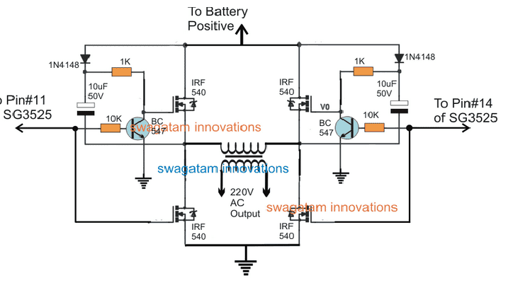
I would suggest you to try the basic design first using mosfets and 12V supply. If it works OK for you then you can upgrade it with high voltage and IGBTs:
bad hide side drive, because 1kohm slow charge Gate, Need to Active Transistor replace with 1Kohm.
Reduce it to 50 ohm 2 watt, the original design is a basic test design. The circuit is intended to be as simple as possible, upgrading it too much would defeat its simplicity…change 1N4148 to BA159
Hi Swagatam,
Congrats! Your web page is cool.
I am looking for good recomendation concerning 1000 VA converter 230V/50Hz to 110V/50Hz.
Do you think using IRS2453 could be good idea?
I have the EG002 (EG8010) in my mind.What would be your idea?
Thank you in advance.
Andy
Hi Andrzej, I think the EG002 can be an easier option, but I can’t figure out how this can be used to convert 220V to 110V? If you use PWM then the average voltage will reduce to 110V but the peak will still remain 220V. A transformer is perhaps the ideal option for converting 220V to 110V.
Hi Swagatam,
Thank you so much for your prompt answer. Regarding PWM you are absolutely right.
I am looking for the solution without transformer – step down converter.
Can you suggest one?
Output voltage could be distorted, no need of ideal sinus.
I appreciate your support very much.
Hi Andrzej,
For 220V the peak voltage is 310V and for 110V it should be around 160V
But without a transformer the peak will remain 310V for 110V sinewave, which is not good. I have no idea how this can reduced to 160V without a transformer?
So I think without a transformer reducing the peak to 160 V may not be possible, or maybe I do not know how to do it.
Hi Swagatam,
Thank you very much for the clarification.
Best regards
Andrzej
I have installed a global inverter circuit using discrete transistors. When I test with 12VDC supply from battery the circuit works fine. Output 11.8VDC, frequency 50Hz. However, when I increase the supply voltage to 42 VDC from behind the diode bridge of an iron core transformer. Then immediately a BC546 (high side) was short-circuited. The corresponding mosfet is also shorted. Can you give advice on this case. Thank you very much.
I think it is due to high voltage spikes which may be destroying the transistors. Try installing 100 V or 150 V rated transistors and see if that helps or not.
Thank you for your quick response chings. Can I replace it with the corresponding type ?
I used Mosfet IRF740, transistor BC547.
Yes, you can replace them with other variants rated at 100V or above.
Bonjour Monsieur,
I am trying to design a full bridge using two IR2153 (instead of IR2110 in your schématics).
I want it to be driven by a single Hall effect IC to replace the RC resonator of your suggested oscillator circuit which triggers the IR21xx ICs.
The purpose is when the Hall IC is High, current in the load will flow one way and when low, the other way.
Any idea ?
Thanks
Hello Lhopiteau,
The IR2153 has a built in oscillator, so it cannot be driven by an external signal from a hall effect sensor.
Hello sir
I’m Jose a freshman in electronic engineering.
I have a project at home which I basically want to achieve inversion of 230vdc 60 amps 50hz to 230vac 60 amps 50hz pure sinewave.
I therefore inquire if I can use a thyristor or how can I go making such inverter with which components specifically?
Hello Jose,
Unfortunately a thyristor cannot be used for switching a DC supply. You will have to implement one of the full bridge designs explained in the above article.
You can first try the basic square wave full bridge inverter as explained above, if you succeed with it then we can proceed with the sine wave integration.
good work, what is that some wave inverter all about
Hello sir,
I’ve just implemented the other H-bridge with 555IC but I’m yet to connect a power source.
So,my question is should I apply at the input labeled battery the 230VDC 60amps or should be a smaller voltage than the 230VDC?
Thank you sir.
Hello Jose,
I think you should first try it with a lower DC voltage, maybe a 12V or 24V, and if it works only then go for the 220V DC.
Hello sir,
I’ve followed and built the second schematic which uses IC 555.
I therefore request if I can apply the 235VDC 60 amps on the input labeled battery or should I not exceed a certain Voltage limit?
You should strictly apply only 12V across the points labeled as battery, otherwise the IC 555 will burn.
Hello, excuse me
I am a final year student and I have to finish this project I am sending you the schematic of the circuit and please guide me what kind of MOSFET to use so that the circuit works well and is not expensive.
Also HIN-LIN waveforms
What do you think I should remove or add in the schematic?
Any help, I thank you
sorry for english
https://freeimage.host/i/gUtZE7
https://freeimage.host/i/grbGDb
From the diagram it seems you are trying to use a transformer as the load across the H-bridge circuit. The connections look OK to me.
I hope the mosfets and the transformer winding ratings are in accordance with the VDD supply
Hello
I measured the gate input voltage of the MOSFETs and it was about 4.3 volts.
Can this low voltage cause MOSFETs to heat up?
To increase the amplitude of my PWM pulses.
have you any recommendation
Yes 4.3V will normally heat up a mosfet since most mosfets are rated to work with a minimum of 9V gate voltage.
However your readings might be wrong, because the output of an H-bridge IC can be in a form of a high frequency, which may not allow you to measure the gate voltage correctly.
PWM amplitude is not related to the output voltage of the H bridge, the Vcc voltage is related to the output voltage from the H bridge. The Vcc should be ideally around 12 to 15V. The PWM peak voltage should not be higher than the Vcc voltage.
In your case as I mentioned earlier, a 900V mosfet can never be used with 4500V supply.
If we use a voltage boosting transformer, should we still use MOSFETs with a voltage of 6000 volts?
According to the design, the primary voltage is about 300 volts, which is converted to 4500 volts in the secondary.
According to the above information, is it correct to choose 2SK3878, ID=9A, VDSS=900V MOSFET?
If you are using the 4500 V across the drain/source of the mosfets then the mosfets will need to be rated at over 5000 V or 6000 V. If you are using 300 V across drain/source of the mosfets then your existing 900 V mosfet will be OK.
Thank you for your response
This internal dead time (IR 2113) is enabled, or needs to be enabled.
In which part of the datasheet is it referred to?
Unfortunately it is not mentioned in the datasheet but it is an understood fact that dead time will be existing in the IC by default. If suppose the IC does not provide a dead time internally then the IC will simply not work and it will keep blowing the mosfets which I don’t think the manufacturers of the IC will allow to happen.
This IC is popularly used for making inverters and in no circuit diagram an external dead time has been seen so far.
The main thing is that the mosfets must be rated much higher than the load supply specifications. If the mosfet rating is less than the input supply then it will keep blowing.
No, the output voltage is completely DC and the output ground is connected to the MOSFET ground with a 22 nanofarad capacitor
If the mosfet supply is DC then it is fine, but make sure mosfet VDSS rating is higher than the supply voltage used.
For MOSFETs, I used 2sk3878 with 900V voltage and 9A current.
In this circuit, the output voltage is 4500 volts with a current of 0.005 amperes
900 V can never handle 4500 V supply. The MOSFETs must be rated at least at 6000 V. Meaning the VDSS should be equal to 6000 V minimum.
Yes, the output voltage is DC
This is the circuit diagram for creating dead time.
which is designed for a delay time of 1 microsecond
https://freeimage.host/i/UteuFp
Do you think it is well designed?
The IR 2113 already has a dead time built-in, so there’s no need to create an external dead time.
Thanks for your tips
I create a voltage of 4500 volts using a step-up isolation transformer.
The primary voltage of the two ends is around 300 volts, which the transformer converts to 4500 volts.
How can I send you the map?
If you have used the second diagram from the above article then I can understand the design, no need to send the diagram. However if you want to show the diagram, you can upload it to any “free image hosting site online” and provide the link to me here.
I guess you have used 4500V DC across the drain and the ground of the mosfets. Please Remember the 4500V must be a DC, not AC, otherwise the mosfets will burn.
In that case you will have to upgrade all the mosfets and the capacitors to high voltage rating as suggested in my previous comment.
Thank you for asking this question.
Are you sure the output is 4500 voltage?
Which mosfets did you use? For 4500V output the mosfets must be rated at minimum 5000 to 6000V
Hello
Thank you in advance for sharing your experience.
I am building an H bridge.
80 kHz switching frequency.
The output voltage is 4500 volts.
The driver used is IR 2113.
Designed for a dead time of 1 microsecond.
Problem:
When I test the driver without connecting to the MOSFETs, everything is correct and there is no problem.
But when I connect HIN1/LIN2 MOSFETs Q1 and Q4 and HIN2/LIN1 to MOSFETs Q2 and Q3 and connect the drain voltage, one of the MOSFETs and two IC drivers burn.
Please help me
At 4500V the risks can be very high.
You will have use mosfets that are rated at 6000 V, and the bootstrapping capacitor must be rated at 10000 V. You must have reverse diodes rated at 10kv across mosfet drain/source.
The Vcc pin of the IC must be protected with a 1K series resistor, a filter capacitor, and a 12V zener diode.
The mosfets must be connected as close as possible to the IC. The +/- 4500V DC bus line must have a non polar capacitor rated at 10uF / 10000 V.
Also remember that the HIN and LIN polarities must be perfectly opposite while switching. Meaning when HIN is high, LIN should be LOW and vice versa.
Another thing is that, if you are two IR2113 ICs, the HIN pin of one IC should be connected with the LIN pin of the other IC, so that the mosfest are able to switch diagonally.
The second question is where the last two Gates NOT are connected in the 4049 circuit
Those two gates are extra gates in the IC, they are not used. Just connect them as they are shown in the diagram.
Hello Boss, I built the IRS2453 circuit and it worked but where I have issues is, when I connect 1k across the gate/source of each MOSFET, the output voltage is around 144v instead of 220v but when I remove the resistors, it gives me 220v. Transformer is 12v/220v. Pls what could be reason for this?
That’s great Patrick,
1K should have been fine, I am not sure why you are facing this issue. You can try replacing the 1K with 4k7 or 10K resistors and see how it works.
Thanks for your quick response. I have used 10k yet i can’t get 220v. With the resistors at the gate/source pin, I realised about 4v on the load(where the transformer is expected). Don’t know if the 1uf used for bootstrapping should be made higher, perhaps that might solve the issues.
In that case I think you can eliminate the gate/source resistor for the high side mosfets. However keeping it connected on the low side mosfets won’t have any problems.
Thanks Boss, I’ll try this one and give you a feedback soonest. I sincerely appreciate your good contributions.
Sure thing! Let me know if you have any further questions.
dear Swagatam;
I was able to bridge h with help from this site. thanks but i’m trying to make my circuit better. I want to add IR2110. My circuit is running at 20khz. What are your thoughts? frequency generator ir2153 or (sg3525) hin1 and hin2 connections should be. and your thoughts.
Thank you Mesut, I am glad you could build the H bridge circuit.
you can use the frequency generator circuit which is shown in the 3rd diagram using 4049. Using SG3525 or IR2153 can be quite complex.
in the picture inspect (mosfet gate R5 and R7) does it act as a voltage divider? then mosfet gate (10.4348volt) then R5=47ohm R7=10kohm mosfet gate (11.94volt) wouldn’t the mosfet gate be nicer? Can I use D5,D6,D2,D3 ST4148 diode? and what is the meaning of this diode?
I finished this circuit with IR2153 and IR2111 and I am making my final preparations to try it. I have to calculate the resistance values well, I don’t have much luck if I burn it.
sorry for english.
The gate/source resistors are to increase working efficiency of the mosfets, so that their gate capacitance discharges as quickly as possible during OFF times and the mosfet generates less heat. The diodes also do the same thing, discharges the gate capacitance of the mosfets quickly during OFF times
yes you can use 1N4148 diodes.
Full bridge to drive DC motor ,DIS,about dead time,then pwm1,pwm2,to drive,one way,or back,direction,what,s happen and circuitry how to drive by logic signals?,, ,,,no answer
Hello, thank you for your scientific help. Please help me by using irs2453 and ir2110 for induction furnace circuit. Thank you.
Hi, you can perhaps try the following concept:
https://www.homemade-circuits.com/induction-heater-circuit-using-igbt/
Sayın SWAGATAM.Transistor ve 555’entegreyle yapılan H köprü inverteri yaptım fakat devre çalışmıyor sorun nerede? düzeltip bildirir misiniz? Teşekkür ederim
Hello Sezgin, without checking your circuit practically, it can be difficult to understand the fault.
I am waiting your working circuit schematics please
All the above circuits are tested and verified designs. They have been tested by many of the readers.
Can i also use two of this dual IGBT?
FF150R12RT4
IGBTs can be replaced for MOSFETs, but I am not sure about the specific number you have mentioned.
Thank you very much sir ????
My pleasure!
Hello sir, according to the final circuit do I need to use resistors to discharge the gate capacity?
Hello Buddhi, resistors are not required, gate capacitance is discharged by the BC547 transistors
Me encantan esos proyectos me gustaría hacerle una consulta espero vea mi comentario
hi, can I use this method for product frequency above 1MHz?
I need help troubleshooting the half bridge inverter using a IR2110. Can you help me out?
Hi, I would like to use a 4049 to make a oscillator and use a IR2110 to make a half bridge for creating a wire power transfer circuit. However, I just have one rectifier, and cannot fully apply your circuit. How can I modify your circuit above, so I can make my circuit work? Thank you!!
Hi, you can use a single diode rectified voltage, by including a high value filter capacitor across the rectified lines. The capacitor could e in the order of 500uF/400V
Sir,
Mosfets connected to pins 13 and 8 do not switch ON at all. accordingly no output power.
do you have any comments.
Thanks
Please check the frequency across the Ct capacitor, if you get a frequency there, then your IC is oscillating and the MOSFET may be faulty, if no frequency then your IC is faulty or some other part/connections are faulty…
Any oscilloscope can quickly indicate the working of the IC.
Sir,
RE:Simple full bridge inverter using driver IRS2453dpdf
I just made similar circuit using 20VDC battery with voltage divider (16V power tge driver) but l used mosfet FQP16N25 instead of IRF540.
at the end the circuit not producing AC power at all.
l am not sure what is the problem, is it the mosfet type or what.
I appreciate your advise. Thanks
Sam, did you connect the shut down SD pin to ground. Please check out the revised diagram, showing the SD pin connected with ground, and 1k resistors connected across the gate/source of all the MOSFETs
Yes sd pin connected to the ground, also today l connected 1k resistors to the gate of mosfets.
mosfets connected to pins 8 and 13 never switch ON. other two mosfets used to switch ON.
Thank you so much sir. Sir my question is about the first design (IRS2453). Those it means the ic is manufactured with the bootstrap and death time circuitry, or we can still add them to the circuit? Thanks hope to hear from you soon
The bootstrapping is already added in the circuit through the relevant diode and the capacitor, however, the values of these parts may need some variations depending on the frequency specifications of the system…
OK thank you sir like in my case the frequency is 50 to 60HZ and my DC supply is from a 48v serially connected battery instead of the rectified 220v ac than from there my output AC will be fered to the primary of a step up transformer to get my 220v AC. I hope there shouldn’t be any changes with the circuit. Thanks in advance
Yes, no serious changes required, except the bootstrapping capacitors which could be increased a bit until the most optimal MOSFET conduction and power output from the transformer is achieved
Am so greatfull sir but still am confused when you say “the value of the bootstrapping capicitors could be increased” Do you mean the capacitance or voltage rating of the Capacitors?, or are the capacitors non polarized type? Please sir can you kindly propose the capacitor values for me?. And lastly how can I provide a feedback circuit for my 220v stabilization? Thanks so much sir mey the lord be your strength ????.
It is the capacitance that may need to be increased, not the voltage rating. You can refer to the following diagram for the values
Once you complete it successful we can discuss the feedback.
Sir I need a complete guidelines on inverter design from scratch typically pure sine wave inverter using iron steel core transformer
George, You can read the following articles for the required information
Inverter tutorial
convert square to sine
Hi Swagatam, hope you well.
Hope you can help me with an idea i have with this named IC, called IRS2453(1)D.
Firstly, what is the chances to use two Hall effect transistors to do the timing of the IC? with other words, I have a rotor with say 10 small button magnets on, alternating between north and south. Then, using latching Hall effect tr’s which get switched on and off my the north and south magnets. then to use that switching sequence as the CT and RT timing for the said IC.
Secondly, my need is to use 2 of the said IC’s as to control a type of motor with the following working condition. the motor has 4 sets of electro-magnets and sits at the following positions, one at twelve o’clock and six o’clock and then the other two at three o’clock and then obviously at nine o’clock. The 12 o’clock and 6 o’clock works together and then obviously the other 2 works together, but with the distinct difference that at a one moment the 12 o’clock electro-magnet is a north pole and the 6 o’clock is a south pole. Then the next moment the sequence is reversed and the 12 o’clock electro-magnet has a south pole and the 6 o’clock has a north pole. Obviously the other pair works in the same manner due to the full H-bridge sequence and topology.
It has to be understand that when the one set op electro-magnet poles are sw’ed on the other pair has to be off. There has to be a certain on time and off time as to push and pull the magnets on the rotor to be moved. For better understanding of the motor, the rotor has 8 magnets which means at one moment each of the electro-magnets has 2 magnets, one north and one south. Thus when say the 12 o’clock eletro-magnet is sw’d on and forms a north pole, the it will push the north pole magnet on the rother and obviously pulls the south pole magnet. again it will be understood that the opposite electro-magnet will form a south pole and here again the logic is the same by the fact that the south pole magnet on the rotor will be pushed and the north pole magnet will be attracted. It will be then understood that this is the sequence of the other pole pair as well.
Here is where my first question came up as to see if i can use button magnets on a smaller rotor which is spaced accordingly as to sw on and off the hall effect tr’s as to cause the timing of the 2 H-bridge IC’s, causing the correct timing of the IC’s. It must beobvious to you now that i need to have a perfect sequence between the to timing H-bridge IC’s.
In fact Swagatam, this is a simple sequence when one uses a commutator, but its not the technology i want to use, but rather a electronical way and this said IC’s working is so simple that I am sure there must be a simple way to do it. My experience is 2-way radio’s and the repair of it and not in design of circuits as you are experienced in. Thus my reaching out to you and see if you might be able and eager to help as i get the idea when i went threw your web site that you enjoy designing and thinking outside the box.
So my friend, hope this i tried to explain to you is understanding and that it might inspire your to the point of thinking about it and design if necessary to help me in my little project.
Hope to hear from you and have a great day!
Regards
Ben Burger
Thank you Ben, I have understood your requirement, but I am having difficulty figuring out how the 4 sets of magnets can be switched with an H-bridge configuration.
It may be possible using a sequential IC such as a 4017, but not with an H-bridge, according to me.
Hi Swagatam, thank you for replaying…sorry my friend, I tried to explain the motor by saying there is 4 electro magnets where in fact there is 8. The purpose was to make it as plain as possible as to ensure you get the idea i tried to explain by using the analogy of the clock and the position of the electro magnets on the clock. There is in fact 2 electro magnets next to each other with a bit of a gap between them and the next 2 electro magnets. Its then also important to know that with 2 sets of electro magnets….which is directly opposing each other, there is 3 magnets for each set of electro magnets, which interact with the said electro magnets. It must be understood that when this two sets of electro magnets are active, on eletro magnet has a north pole and the adjacent electro magnet is then a south pole. At this specific moment of operation, with the one electro magnet a south and the adjacent eletro magnet a north, it causes the 3 permanent magnets to be pushed and pulled. It should be obvious that the operation of the opposite set of active electromagnets works exactly the same at the given moment. At this precise moment, the other two sets of electromagnets which is inactive, has each 2 permanent magnets right across it. With the rotor which is turning a few degrees the inactive electro magnets gets turned on and thus push the PM away as well, adding to the torque.
I hope I made the operation a bit more understandable.
I have considered the option of using a sequencer but came across this H-bridge IC and was wondering if it might work better.
I don’t want to put the motor diagram on this forum but if you like, as to understand this motor’s operation i will send you a sketch of it to your personal email address.
hope to hear again from you.
Friendly regards
Ben
Thank you Ben, I have already understood your explanation, and therefore I said 4 sets of electromagnets which corresponds to 8 electromagnets, where each pair is connected opposite to one another.
H bridge cannot be used here, because H-bridge can be triggered only through 2 complementary pulses, for operating a single flip-flop load.
If you are having other alternatives for operating this set up, then you can surely try them, because a Full bridge or an H bridge does not appear to be feasible for this application.
Hi Swagatam, thank you for your replay and have a great day.
Regards
Ben
You are welcome Ben….
hello sir I need to make 24V dc to 220 AC 2kw inverter without using transformer can you please help me to chose the circuit diagram for that
For what you need this ? make from 24 vdc to 240 ac you need transformer.
Hello Amin, you can try the concept explained in the following article:
https://www.homemade-circuits.com/5kva-ferrite-core-inverter-circuit/
But it is meany only for those who have reasonably good experience and knowledge in the field of SMPS dsigns
Hi can i ask you in circuit with IC IRS 2453 D can I use H-bridge SKM400GB124D Semikron IGBT Module 1200v 400A ? instead irf 540 . I just need 200 A for aluminium welding.
Hi, yes you can use it.
Many thanks
Can i ask you : In aluminium welder there is foot pedal for restriction current when welding aluminium.
This current restriction is for regulation put down current when material is heating up.
How i can restrict, put down current in this circuit ?
Thanks, You can do it by adding a current limiting resistor in series with the ground line between the ICpin2 or Ct ground point and the MOSFET ground point. And then connect the SD pin with the MOSFET ground point.
The value of the resistor will decide when the IC shut down is activated for limiting the current
thanks
Dear sir, I am making a 1000 watt 24 volt Inverter using the above full wave bridge circuit. I am confused regarding which Transformer to use? Can I use a single tap 24 volt transformer rated at 30 amps? I will be using 2 x 12 volt 150AH Batteries in series to make 24 volts.
Firdosh, yes you can use a 0-24V/30 amp/220V transformer but 30 amp will give 1000 watts, you will need minimum 50 amp
Is the circuit with the Ir2110 mosfet driver suitable for making a 100 watt solar panel inverter?
The power output depends on the MOSFET rating, so you can get any desired power output simply by upgrading the MOSFETs accordingly. 100 watt can be achieved using IRF540 or any similar mosfets
Brother, is there any N channel mosfet and P channel mosfet pair that has Vds of >400V and how do I know how much resistance of resistor should I put to the gate of mosfet if I ever replace the 4 mosfet in the first circuit diagram which uses IRS2453D and what to do to increase the power of it? Thank u very much in advance.
Hi Martin, you can use any 400V P channel mosfets but add 4 in parallel on each channel
For N channel you can use any standard 400V N mosfet and use single MOSFEts on each channel.
For the gate resistance you can use 220 ohms
Brother, what is the maximum power of the first circuit diagram which uses the IC IRS2453D and four IRF540 mosfet? Thanks in advance.
It can handle up to 300 watts
Como vai? Tem um esquema mais simples, para mandar sinal HIM LIM em um ir 2110 / Obrigado.
It is given using IC 4049…it is a simple design to drive HIN, LIN
Again sir, please help me understand the meaning of “SD being used for shutdown” is the shutdown same as switching off the inverter,how then can this be achieved? Please help with a diagram is possible.
Please go through the pinouts functions here
https://www.homemade-circuits.com/understanding-sg3525-ic-pin-outs/
Shut down will shut off the output of the IC, which will switch OFF the MOSfets completely.
Hello sir swagatam,how is this achieved is it by the use of a scr? If so can you help with a diagram showing the connection?
Evans, you can connect the SCR cathode to SD pin, anode to `12V supply, and gate to the input signal through a 1K resistor
After the ic output is shut down through the SD pin ,how is the system reset back again?
the outputs restores cutting off the feedback and the inverter begins working again.
Sir swagatam,how can I advance the circuit to produce a pure sine wave with pwm, kindly help me with a circuit diagram if at all it’s possible to integrate pwm to the system,thanks.
Evans, for this you will have to integrate the SPWM to the low side MOSFFET gates, it is not difficult, but making the basic full bridge design could be difficult
sir swagatam,can a 20v transformer charge a 24v battery? also sir help me know how calculate the current of a transformer at no load? coz i have a transformer with an output of 20v,input is 240v but it has no indication of the current. But te secondary site the coil gauge used i can see awg6. help please ill appreciate.
Hi Evans, yes it can after adding a bridge rectifier. After rectification the output from the bridge will be 20 x 1.41 = 28.2 V.
To know current output you can connect a 20 amp ammeter in the AC range directly across the secondary wires for a couple of seconds, and check the reading.
oooh,thank you sir swagatam. now one more question
what if the current is more than 20?
cause the transformer is very huge like 30kgs,wont it destroy the ammeter?
The meter range must be approximately 2 times more than the anticipated current from the source.
Hello sir swagatam,how about the irs2453(1)D circuit diagram full bridge? Is it difficult to build full bridge using the chip? Again sir ,is there any need for a bjt stage for this chip design? If so how to go about it?
Evans, if you do everything correctly then the chances of any damage to the MOSFETs can be less. You will have to experiment with the 1uF capacitor, which could be anywhere between 4.7uF to 22uF. While doing this make sure to connect a appropriate bulbs in series with the drains of the MOSFETs, the bulbs must not illuminate without a LOAD attached, this will confirm the inverter is working OK.
Ok sir, what’s the formula for calculating the values of CT and rt?
Hello sir swagatam, suggest for me any spwm that you have ever posted that is compatible with this ic irs2453(1)D that won’t give me a hard time integrating since I don’t have any scoop to view the wave pattern.
without scope it can be very difficult and may result in failures….
Thank you sir for the response,if I could ask, should I cut off the oscillator from the gates or cut off the supply to the oscillator or cut off both?.
Evans, cutting of power to the oscillator IC should be a better option, which can done with a single SPDT relay. But make sure to keep a 1k resistor permanently connected across all the MOSFET gate source pins.
Very well noted sir
Evans, it actually seems quite easy, since the external diodes are in a bridge formation, we simply need to cut off the gates of the MOSFETs from the oscillator IC through a DPDT relay, when AC mains is available at the grid output, Simultaneously, transformer secondary side will also need to be switched to the the grid AC side via another DPDT relay. By default the MOSFET gates must be connected to their sources via a 1k resistor.
I will try to update the info through a new article soon.
How is the setting of the 10k preset?
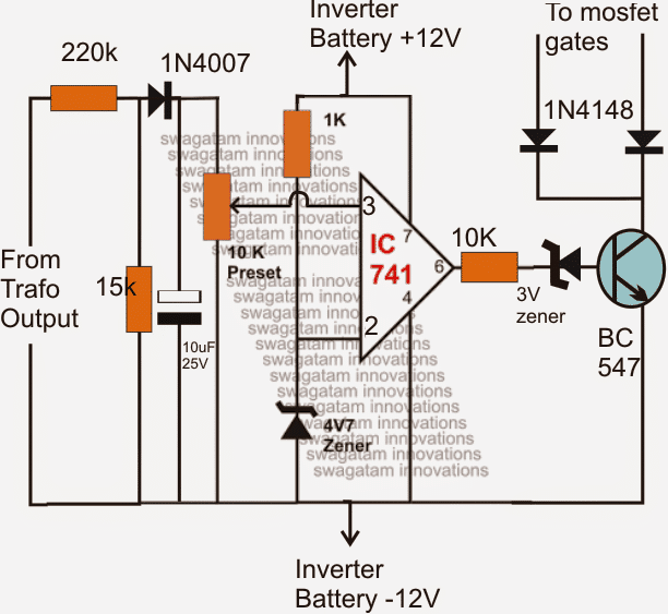
Again instead of using the inverter output directly,is it advisable to use a separate power supply say a feedback transformer?
finally i thank you for your quick,unconditional responses
very well noted sir,thank you very much
Glad to help!
Feed 220V on the left side (220k side), adjust the preset until the transistor just activates. That’s all.
You can replace the 3 V zener with an LED to get the direct indication of the cut off activation when the inverter output goes beyond 220 V
Sir from the above circuit irs2453(1)D,if was to integrate spwm with opamp,which pins of irs2453 will give me low and high pulses that I should feed to the opam (-)&(+) inputs?
You will have to do it in this way
THe slow triangle to the op amp should come from the CT pin of the IC, and fast triangle can be from any other source such as IC 555 etc
Hi sir,i constructed this Inverter and it’s working fine. I was thinking of converting it to an inverter charger using ;
1. Same transformer
2. Mosfets body diodes
Again another concern is how to boost the charging voltage because I used a 0-14v transformer and I need to charge my 2 × 12v 200Ah batteries fully.
Please sir help me with step by step circuitry so that I can implement this thanks.
Hi Evans, I will have to research the concept, if it’s feasible I’ll try to post it soon. For boosting you will have to employ a boost charger, as suggested previously.
hello sir swagatam,please how can i maintain the stability of the output irregardless of the loads or no loads at all?
help with a circuit diagram and the connection to this irs2453 circuit
Evans, you can do it using the following circuit
You can remove the diodes from the transistor collector and the connect the collector directly with the Ct pin of the IC.
Wooow,sir u can’t imagine how of help you’ve been,thank you very much and May the Almighty God bless you. Sir can mosfets be added in parallel for higher currents? How can this be done,is there any changes to the circuit? Or is just connection of drains, sources and gates together? How will the gates be driven?
Thank you Evans, you can connect more MOSFETs in parallel without any changes in the circuit. Gates will be driven in parallel.
Hello Sir
This circuit looks very interesting. I am working on making such an inverter circuit but with a three phase output from a DC input. May you please assist me with a circuit diagram and code if it has to include some coding.
My last question is how do you compare the suitability of microcontroller based designs and the IC above if the intended application is converting DC from solar to three phase AC
Hello Morgan, you can try one of these designs:
https://www.homemade-circuits.com/arduino-3-phase-inverter-circuit-with-code/
Arduino is absolutely not necessary for making any inverter, to me it’s an overkill unless there’s some specific reason behind it.
Good evening Swagatam,
Your discrete h bridge inverter circuit without the ic, how many wattage is it? Pls can you design a 5kva discrete h bridge inverter without the ic?
Hello Freedom, it will depend on which MOSFETs you use in it, the ID and the VDSS of the MOSfeT will decide the max wattage.
sir i want to use IR2153 with inbuilt programmable oscillator having formula for f = 1/(1.4 x (Rt + 75ohm) x Ct. if i calculate the switching frequency of oscillator using its low & high pulse for mosfet driving as 50Hz. will it not be the same as the output frequency provided to the load?
Sheraz, the high pulses across Ct switches the high side and the low side outputs of the IC sequentially, therefore for completing each cycle (high + low switching) at the output, the Ct frequency will need to be 100 Hz, as per my understanding.
dear sir! what will be the switching frequency of the mosfets or IGBTs produce by ic IR2453 for 50Hz output wave or it is 50Hz determined by calculating Rt & Ct pins of the ic?
Dear Sheraz, according to me it should be 100 Hz across Rt, Ct. 50 Hz should be at the mosfet bridge output
Please sir ur digram is correct but it was not a without center tap project… I am purchase this transformer(without center tap) sir…. Please recommend other sir.. In ur inverter project i show many inverter project in which using ic 555 and without centre tap… Except two batteries project… Can i choose one of them… Sir… And also suggest me which one is…
Apurva, IC 555 or any similar oscillator IC will always require a center tap transformer for an inverter configuration, unless two batteries are used.
Ok sir… I am agree with ur rply but sir can u provide me without ic 555 and without centre tap transformer project. Even it has complex than also i can tryfor make it.. But their parts will common which are found in my place…. I send u one cricuit diagram in ur email id see it and clarify it it best for me or not… And also give me some knowledge about that circuit… Please sir i always believe on u sir… Please help me
Apurva, I did not receive any email from you, please show me the link here!
(wordpress@162.240.8.81) it is ur link… Where u send me a msg…..and i am also send the cricuit digram in this link….
Can you show me the link of the diagram instead? or the link of the article?
This ic not present in my place. Sir
Other two ic whivh have same configuration i search in Google but they also not found in my place sir… Please recommend common full bridge drivers ic aur if other suitable diagram which have using ic 555.. Please send me… Please sir i am very happy if u can do for me… Please sir
Hi Apurva, In that case you will have to use two batteries for making a full bridge inverter using any ordinary IC like 555 or 4047 etc. You can even use the following concept with two batteries for getting a full bridge output
https://www.homemade-circuits.com/2012/09/mini-50-watt-mosfet-inverter-circuit.html
Sir i show in ups box 600va/360w where we can take this transformer…. And i can check it with 2 bulb100w but time will be to not measure… How much will be glow it
If you do it, the battery will get damaged quickly…
7amp x 12=84watt then i can use four 12v 7ah battery then it given 300watt power sir… Battery will connect into parallel connection….
yes that’s possible.
Thanks sir… One more question can i use irs2453D instead of any pwm driver… Please recommend me.. Sir
Sorry for writing in to comment… Sir i want know can i use any full bridge drivers ic ir2453 in place of any other ic which have same configuration.. Because it was not found in my area… Please suggest me…which ic used in place of this ic…
Yes you can use any full bridge IC and make the circuit as per its datasheet.
Apurva, this IC is a full bridge driver IC, it is not a PWM driver, it will only provide you a square wave inverter, but an very efficient full bridge inverter
but even then battery will get damaged if it’s used at its full 7Ah level.
Please rply me sir i am waiting for ur answer… And also tell me can i use ic ir 2153 in place of it…
IR 2153 is a half bridge IC, you will need two of them to make it full bridge.
It contain ac power supply for run this this project… But i want run only battery power supply sir.. And used of without centre tape transformer… Because these item would be purchased… Now
You can run it with battery also. Just connect the pin#1 of the IC with the upper line, and then you can use 12V battery across the upper line and the lower line.
How much watt will generate by centre less tranformer output supply sir.. If i use 600va ups transformer…
It will depend on the battery also. With 7Ah you are gong to get not more than 50 watts for an hour.
Can i glow 2bulb of 100w by this project… Aur not
But sir… When this transformer present in ups which are operate by 12v 7ah battery and produce 360watt output how it is possible sir…
did you practically put 360 watt and check? 360 watt will draw 30 amp current… from where will the battery will bring 30 amp? 7Ah can produce maximum 7 amp current, and at this rate it will be flat and destroyed within 30 minutes. Even at full 7 amp the max power will be 7 x 12 = 84 watts
If i want generate 500w from this cricuit… How much amp battery used with this ups transformer… And also clarify me Can this ups transformer oprate 500w output power… When i introduced ur recommended amp battery…
Yes can get 500 watt from a 600va transformer, You will require minimum 200Ah deep-cycle battery for this.
When I have already said that with 12V 7Ah battery you can operate only 50 watt load, then how can 2 100watt work? Please learn the basics first ans then attempt these complex circuits.
sir
can u suggest any outher h bridge driver ic for high voltage operation . so these ic is not availble in my location
Naseef, you can Google search for “full bridge driver IC datasheet” you may find a few alternatives online…
Hello.
I am discovering your blog and i have a question about your
f = 1/1.453 x Rt x Ct where Rt is in Ohms and Ct in Farads.
I thought f=1/2piRC
What did I miss?
Regards
Hello, the formula is specific to the IC’s internal configuration, it is suggested in the datasheet of the IC on Page#9
https://www.infineon.com/dgdl/irs2153d.pdf?fileId=5546d462533600a401535676951e27c3
Sir also help me with a diagram for spwm best for this circuit IRS2453(1)D and how to integrate it, thanks.
Evans, the following article explains a basic spwm set up circuit
https://www.homemade-circuits.com/how-to-generate-sinewave-pwm/
Sir please help am kind of not getting the whole concept about the formula, please if possible,give me an example say calculate 50hz,using the formula f=1/1.453×RT×CT. The reason why I am not getting this is that,in the formula,we have two unknowns,how do I go about it. Incase sir you have fixed values for CT and RT to get 50/60hz can help me with, thanks.
You can take any arbitrary value for either Rt or Ct, and then solve the formula. Alternatively you can confirm it practically through a frequency meter. Ct will be farads and Rt in Ohms
Sir
I want to make a 150v dc to 110v ac invertor . So can i give 150v dc directly inthe +AC and -AC . Or should i make any changes inthe ckt befor it ??
Thanks
What should do sd pin (5). Thre is any connection .
as per the technical specs of the IC it can be kept unconnected, still to be entirely confirmed you can ground it through a 10K resistor….because only a high logic can enable a shut down on this pin….
yes you can do that, make sure to supply the IC Vcc with a separate 15V
Sir I make this circuit,at 50hz if 24vdc apply on bridge at load point 15v ac but if 50v or more voltage apply ic and MOSFET damaged.we use bootstrap capacitor 104 if use 105 no drive volt
yogesh, as you can see, the mosfet positive is separate from the rectified line, the IC will need to be separately powered through a 15V source, while the mosfet rectified line from the intended high voltage source.
the mosfets should be rated accordingly to prevent damage.
I will investigate that circuit and try to design something. Also I will check on your circuit, but maybe I will need some modifications, as the “battery” in my case are the rectified 220VAC. Let me investigate and I will be back on you as I have some to share. Thanks for your reply sir. Have a nice day Swag! 🙂
OK, no problem! wish you all the best!
Dear Swagatam, I sent to you a message in this page a few days ago. At the beginning it said “comment under approval” or something like that. Now I can’t see my message. I’m wondering if you have an automatic spam filter who thinks I’m a robot or whatever. Sorry for this message if cause any bother to you. Thank you! Regards!
Hi faktorqm, sorry, did you have too many links in the comment, then may be I might have accidentally marked it as Spam….no problem please repeat your question, if you have links you can post them but after replying I may edit those links and delete them.
Thanks for your reply sir! I will post only one thought. I want to construct something like a universal dimmer for all kind of loads (resistive, inductive) using the pwm pure sine technique. My main goal is to dimm, for example, filament light bulbs or leds lamps (in my country there are dimmable electronic transformers with dimmable led lights) or CFL lamps (only on/off without dimm). I found this link with a circuit but there are no values, and I don’t have an actual idea about how components value I need to start testing.
Thank you very much for your time sir!!
I checked the article, but I am not able to understand how the last designs are designed to operate…according to me there’s no way the IGBTs would be able to implement the dimming function or even power the output, are you able to figure it out??
alternatively you can probably try the following concept for achieving the results
https://www.homemade-circuits.com/2016/04/solar-inverter-circuit-for-15-ton-ac.html
Hi Swagatam, thanks for your reply. I didn’t figured it out but as far as I saw the igbt acts just like a on/off switch, which operated correctly, supposedly, it will deliver the square wave at figure 7 on that link. Then the next network with two igbt’s I don’t know, and the L-C circuit it looks like to be a chebyshev low pass filter with order 2 to obtain a “sine” wave after the igbt modulation. (same as the beginning of the circuit network). I have tried to simulate over proteus just the first igbt, with a square wave on the gate, 50% duty cycle, but the result is not what I expected. Maybe I need to setup the entire circuit with thumb rule component values and… cross my fingers 😛
Regarding the circuit you pointed me out, I have one question, In this one https://www.homemade-circuits.com/2016/05/h-bridge-mains-voltage-stabilizer.html you used an autotransformer at the “exit”. Is this necessary for a dimmer?
Thanks for your time sir!!!
Hi faktorqm, I tried to simulate the circuit in my mind and it seems the first IGBT will work correctly, however its gate voltage will need to be equal to the required output level, because since the output will be following the gate, the gate level will determine the output level. The other two IGbts probably are configured to function like high power switching diodes which work with the coil to form a buck converter kind of network, not entirely sure though.
So technically even if the entire network of the inductor and the two IGBTs are removed still the design could be used to produce a pulsed sinewave by feeding a pulsed sinewave at the gate of the first IGBT, as per my assumption.
In the circuit suggested by me, the coil is used for stepping up the voltage to some desired higher level during the low voltage conditions, in your case this trafo can be ignored and eliminated….
yes, the high voltage rectified -DC will be the common ground for the -15V also, you ca use 1K or even 10K for keeping the SD pin grounded
you can keep floating or a better keep it connected to ground via a high value resistor, because nothing is specifically mentioned in the datasheet, except that anything above 2v will enable the shut down feature on this pinout
yes you are right, the max input supply should be always less than the device's max Drain/Source rating
Hi, yes that's correct, since the rectified bus voltage to the full bridge would be a DC, the frequency from the ferrite core trafo wouldn't have any impact on it.
yes, 150V to the BUS line would allow you to get around 100V AC from the full bridge circuit, at a frequency determined by Rt/Ct
Hi, yes all your mentioned assumptions are correct! You can go ahead with them!
SIR SEND ME YOUR EMAIL OR EMAIL ME AT 'OYELEDUNBUKOLA@GMAIL.COM' VERY IMPORTANT SIR!!!
Can you please draw me the schematic diagram with the parallel MOSFETs because I don t want to make mistake thank u
Hello dear sir
Happy new year first
I'm enjoying your creations thank you
I would like to ask you the circuit of a transformer less inverter my batteries can be from 12v-48v 200Ah
Preferably 6kw-10kw 220volts AC 50hz
I know you said to connect more MOSFETs to the above circuit but I cannot understand how my knowledge is limited
So please I need the full circuit for as it should be
Thank you very much in advance
OK, then you could go for the circuit which is explained in the above article….feed the 330V DC across the indicated AC rectified lines…and use a more number of mosfets in parallel to the existing one to achieve the required 10kW.
you could try IRF450 fets for this….
Thank you for the fast reply if I had the 220v how would the circuit be in order to achieve 6-10kw
Thank you
Happy New year to you demiliza,
to make a 220V transformerless inverter you must have a DC input supply of 330V DC….a 12V or 48V will not work.
Sir, im currently working with this inverter circuit. At first Im thinking on using 2 ir2111 for the driver but now im planning to use the above circuit. What im asking is, is it safe to use ir540n as the switching component with ac rectified input 310v ? Because i've read the datasheet of irf540n and it says 100v pls help me
Uddy, it is not safe because IRF540 is not rated to handle 300V, you can go for IRF840, IRF450 or other similar mofets.
is it a tested design? I would like to do a pcb of this if it is. I know i would have to increase battery AH but for the transformer I would need 6000W so thats 20amps on the 300v secondary, can those output Fets manage that kind of power?
It is a standard design suggested by the datasheet of the IC.
the output fets will need to be selected as per the current and voltage of the transformer and the output load, if needed more numbers can be added in parallel
this is another version for the circuit you did, where the iron core transformer is you can put a ferrite core with 9+9 turns and secondary 300 turns I am not sure if this is one of your designs though.
https://drive.google.com/drive/folders/0B0N-CQJdWSP0NmJwZTc3ZmVQUGc?usp=sharing
What kinda wattage can I get from this and is the wave good enough for sensitive electronics?
ofcourse it's my own design.
it's a pure sine wave design so can be used with any equipment
wattage will depend on trafo wattage rating and battery AH rating
Must there be a load on the output of the h bridge for it to properly function?
Dear sir, I am currently working on a wireless charger and have adopted roughly the same type of circuit as shown above, but with a few changes.
Freq: 100 KHz
Bootstrap cap: 1.0 uF
Mosfets: IRF540
Series gate resistor: 10 ohm
Gate to source resistance: 470 Kohm
The LO1 and LO2 are connected to a 2N2907 transistor and a 1N5818 diode and then given to the low side mosfets. The output is a 17.3 AC voltage but the output from HO1 and HO2 have very bad negative and positive voltage spikes. It would be real helpful if i can bit of clarification regarding the spikes and how i can further improve the circuit.
Thanks
Dear 932, why don't you build it exactly as per the above diagram? I don't think the 2N2907 are actually required.
how much voltage are you using for the Vdd pin of the IC?
make sure it's around 12V, if possible make it 12V and check the response.
I hope you have positioned the reverse diodes across the mosfet gate resistors?
other the these modifications, I don't see any other possible remedies for the preventing the spikes.
and make sure the mosfets are connected as close as possible to the IC output pins.
– What is the maximum frequency of the driver?
Is it 100 kHz?
For my wireless charger application, the frequency is 200 kHz?
can you suggest me another driver if the mentioned one does not work
Thank you
you can easily achieve 200kHz from the above shown design because the maximum range is a lot higher than that.
if your application is not based on full bridge then you can try a 555 also for the purpose
okay sir thanks
Please check it out here:
https://www.homemade-circuits.com/2015/12/laser-alarm-circuit-for-protecting.html
sir can u give me inverter circuit diagram that can convert 20v dc to 20v ac. i try many inverter circuit but still no get ac output and sinusoidal waveform. please help me
Shahril, you can easily convert 20V DC to 20 V AC with square waves, but making it into sine wave can be difficult.
okay sir thank you in fact i don't know how much i can thank you but all i have to you is may the good lord who knows much than we can imaging bless you may you lived long thank you hope to hear from you soon
You are most welcome Daniel, I'll let you know when it's posted.
thank you sir for respond me,sir please my grandfather is un orange farmer and he is having a problem with thief's so he ask me to do something that to protect the farm or anything that can alert him when any thief's or any person try to take away any thing from the farm so i decided to install a CCTV camera,so i need a circuit without a camera or if you can help me out sir i have said this but you can create something that can help me out thank you hope to hear from you soon
thanks Daniel, presently I am working on a similar concept which uses a laser beam to monitor a field premise, I'll post it soon and you can apply it for your cause too..
hi sir please i want you to explain this for me, my question is how can i calculate home appliance with battery i mean if i have 12v 1000watt inverter and 12v 100ah battery how can i calculate to get the hours i should calculate the battery with the appliance or the inverter wattage,it should be division or multiplication thank you hope to hear from you soon
Swagatam Majumdar is correct if the manufacturer of the battery rates the battery at a 10Hr discharge rate. Some manufactures rate their battery's at a 20hr rate. So it's buyer beware on battery's, make sure what the AH rate is based, on 10 hours or 20
Daniel, the inverter power is not relevant, it's the connected load which needs to be taken into account.
Assuming it to be 1000 watt, then by dividing 1000 by 12 gives = 83 amps…so you would require 83 amps with a 12V supply for satisfying a 1000 watt load.
your battery is 100H rated meaning if it's discharged at 100ah rate it will last for 1 hour….but that's possible only in a hugely ideal situation, practically you can assume it to be just for 20 minutes.
so at 100 amp your "fully charged" battery lasts for 20 minutes….therefore for 83 amps it will last for:
100/83 = 20/t
t = 16 minutes only…after this it will be dead flat….and if you continue to discharge it at this high rate within days your battery will be permanently dead.
at 83 amp discharge rate the battery must be rated at 1000 AH
okay sir but i cant see which one you are referring its a lots of 555 circuit there please sir help me with this i have 555 with 4017 okay when i put on the circuit it chop 340v dc but i don't get 220v ac i got 142v ac at out put of full bridge i use 103nf in between pin2 and 6 i got 142v ac 50hz 100k pot but if i replace 103 with 102nf,104nf 101nf i got 220 but i don't get proper frequency if i regulate the 100k pot i 5175hz i cannot take even a bulb please sir guide with this please my English is not good thank you looking forward to hear from you son
Google "PWM 555 motor speed controller circuit" remove the mosfet and the motor from the design and the rest can be used for your purpose…
thank you for respond me sir but 555 pwm circuit it come with only one out put so what should i do because i want to use it to drive most fets by IR2110 or if you can help me to get 555 pwm to fed any ic so that it can drive high voltage 315,320,or 340v dc thank you
you can terminate the pin3 of the 555 IC with two diodes and configure them with the inverter output devices as shown in the following article:
https://www.homemade-circuits.com/2013/04/how-to-modify-square-wave-inverter-into.html
in the above link a transistor astable is shown instead of a 555 astable.
hi sir thank you for this full bridge inverter circuit,sir please i have a inverter circuit 12v DC to 340V DC but now im looking another circuit can chop 340v DC to 220v AC can you please help me one i have ir2110 i don't do programmer so i need that one don't use pic micro chip thank you hope to hear from you soon
Hi Daniel,
you can use any standard 555 PWM circuit and feed it at the base of the driver transistor for controlling the RMS voltage, or alternatively you can simply drop the 12V to 9V using rectifier diodes in series with the battery positive for the same.
Hi Mr Majumdar
What are the most appropriate Rt and Ct values to use for 50hz frequency at the output?
Hi Imraan,
I have no idea about it, you may have to calculate it using the given formula or determine through a practical experiment and a digital frequency meter.
Hello sir
Is it completely safe to apply pwm to only low side of MOSFETs in full bridge only especially in this circuit where I would like to use your pwm circuit.?
I am asking because i have been studying other drivers like the ir2110 which is another IC I am thinking of using as a back up if I can't find ir2453
Now the thing is to implement full bridge using ir2110 I will need to use two of the IC's and then connect the lowside input LIN of ic1(ir2110) to the the high side input HIN of ic2(ir2110) so that that way diagonally they botje turn on causing current to flow but the catch here is that both inputs will receive PWM pulses( chopped 50hz pulses) so this means using the ir2110 the high side output will trigger the high side MOSFET as well as the low side mosfet with this pulses but I want to know it it will be suitable to drive the high side sufficiently.
With this simple ir2453 we can just leave the high side pulse at line frequency (50hz) while we just pass PWM to low side only whixh is why I find it desirable as it saves lots of space and stress.
But my main queation again is will both techniques be ok . just increasing my options.
I'll check it as soon as i finish with my website's pending assignments…
Hello sir,
I forgot to mention that I sent you a mail.
Hello Michael, you can isolate the PWMs by adding a diode and a resistor across the respective LIN pinouts of the both half-bridge ICs, or alternatively you can prefer applying the PWMs at the gates of the low side mosfets for the same.
Hello Sir
That means that the only down side to the h bridge would be that I would require double the amount of MOSFETs I would use for a push pull config.
Example if I use these four N channel on push pull by using two per each side of push pull then at 300w per MOSFET then I would have 600w output. But for h bridge when diagonal are conducting the two diagonal are only supplying 300w when individually they can give 300w each and this is due to the series connection so to get 600w in h bridge I would use 8 n channel MOSFETs.
Is my calculation correct according to your explanation?
Hello Michael,
using a DC DC converter would be like using two inverters in series which could make the system inefficient….moreover to produce 25 amps from the DC t DC converter could be a complex affair as it would require heavy duty coils and mosfets involved.
so it's better to go with a 24V battery directly with the designed inverter and use more mosfdets if required.
Hello sir
If complications arise I will stick to 24v direct from battery input and use as much MOSFETs as possible.I don't want complicated process.
Unless you have a transformer less solution with stable output voltage. Ha ha
Hello sir,
The thing is I can afford to get two 12v batteries that's why I am planning to use 24v input but you just mentioned using higher voltage like 60v or up to 100 but that would mean I have two options
1) using more batteries which I don't want to as more is expensive
2)using a DC to DC converter
Now If I use option 2 as option 1 is ruled out, it means more components added as I have to use oscillator like sg3524 and a small ferrite trafo (puah pull converter) which honestly means component count is getting higher.I don't want that as I want simplicity
A) So I was thinking are there DC to DC converters that employ minimal components only and yet so simple and effective that I can use to convert 24v to 48v.?
B) so if (A) is possible then I connect it to the h bridge, since diagonal high and low side MOSFETs conduct then when at full power the low MOSFETs will conduct a lot of current but my question is since the high side will also conduct current will the transformerless DC to DC converter withstand such current draw at full load to adequately complement its diagonal low side MOSFET.
Hope you get where am coming from.I have seen h bridge inverters using push pull DC to DC converters whose output powers the drain of the mosfets high side but since the transformers are small yet current will flow through them when conducting.
So basically it seems the DC to DC has to be able to output certain amount of current?
Michael, you are correct….but the H bridge trafo can be significantly smaller compared to a center tap topology…so it wins here, moreover you have the option of using higher voltages (upto even 60V or 100V) and get massive power outputs (kvas) without adding a single mosfet to the existing 4.
Hello Sir
Just to be clear, if i have an N channel MOSFET that gives out 300w.then I use four of this on h bridge config.(2 on high and 2 on low side) then my total output should be 1200w right?
.
Remember Power=Voltage times current
If the Voltage across the FET is 1 Volt when on and the current rating is 300 amps that's 300 watts per FET that is on, at a 50% duty cycle, and if the output source is 12 volts after you subtract the FET voltage drops, that's 3600 watts output. total power consumption from source supply is ~ 4200 watts.
Hello micahel, no all the 4 together will help to produce 300 watts only, because the diagonal ones are conducting in series, so no question of power addition, while the left and the right diagonal pairs are conducting alternately.. so again no chance of power adding up.
Hello sir,
I now understand am gratefull.
I have one more question
In push pull config, if I wanted more power output say from 500w to 2000w output I simply add more MOSFETs in parallel and its easier since we only deal with low side switching but now since full bridge uses four MOSFETs,
Once I have my trafo say 0-12/2000w ready,
How do I increase power output using h bridge (full bridge topology)
Basically what do I so to increase power from say 500w to 2000w?
Do I add MOSFETs to both low and high?
Confused.
…yes add more number of mosfets with each of the four existing mosfets
Hello Michael, for an Hbridfge also you will need to add mosfets in parallel for multiplying power output…the rule is same…however you can alternatively decide on a higher voltage trafo…like a 48V primary trafo, and a 48V battery for the boosting power without having to use more number of mosfets.
Also sir pls I still don't get how full bridge works fully.
Could you explain what happens during the low and high side in terms of conducting. I think the low side MOSFET switch according to wave form at its gate but high side?
the diagonal mosfets pairs are switched ON simultaneously, while the left and the right pairs switch ON alternately, generating the required AC across the connected trafo primary.
while the diagonal mosfet switch ON, the high side mosfet is applied with an excess of 5 to 10V than its drain voltage so that it's able to switch ON fully and compliments the low side mosfet, making the conduction complete and full.
Also sir one important question.
Now using pwm we make it as close to a sine wave as possible but for a 12 supply we would need a 0-12/220v trafo but for pwm should it still be 0-12/220 or 0-7/220v to make up for the PWM sectioj just like in the center tap sine wave pwm inverters you have.
for a PWM insertion, the trafo voltage should be lower than the supply voltage to compensate the PWM range
Hello sir
His ic seems powerful and I think we can add pwm to the low side of the driver going to the gates but my question is this.
You said that the gate voltage has to be at least 5v higher than drain voltage for the high side to function properly so now if I power the drain with a +24vdc supply and then use a 12v regulator to power the IC at pin 1, will sufficient voltage come out at the pin 13 and 9 high side output.? To work sufficiently.
2)Also when using a 24vdc supply and 12 DC at pin 1 of the IC the 1uf/25v caps at 14 and 10 can it be increase to a higher capacitance/voltage?
Hello Michael,
with a 12V as the supply to the IC the output at the high side pin would be 36V, which would imply an efective12V at the respective mosfet gate, which would be sufficient for driving the gate optimally.
the capacitor voltage rating is relevant to the supply voltage so I think it can be selected to be 25V
capacitance value are OK, no need of increasing it.
hello, swatagam majundar, inverter circuit on the waveform what? sine or square and how the power output?
thank you.
hello Robet, it's squarewave
I wonder why there are no snubber circuits? Most kinds of electronic high power switches I've seen have snubbers to protect the FET's or IGBT's.
the fets alerady have in-built snubbers, but you can always add more externally for reinforcing the inbuilt ones…
Thank you for your quick reply.
But can you pls give me a simple circuit on PWMs that needs tobe connected to the lower gates of the mosfets.
You can use the PWM design which is shown in the second diagram of the following link
https://www.homemade-circuits.com/2013/04/how-to-modify-square-wave-inverter-into.html
The section consisting of T5/T6 is the PWM stage.
Hello
Eng,Swagatam.
Is the above inverter circuit diagram modified sinewave or pure sinewave
inverter. And also, is it possible to power inductive and sophiscated
device without problem?
Hello Raphael,
it's a simple square wave inverter, it can be converted into a sine wave by inducing PWMs at the gates of the lower mosfets.
Hello sir swagatam,how can this be done? Please a circuit diagram will appreciate.
Please complete the basic design first, then I’ll show you the SPWM integration process..
where did you buy the IRS2453(1)D? because I can not find it.
Sir if i am using a 230 / 12-0-12 300W transformer and one car battery 12 V 35 Ah for producing a minimum of 230 V AC at 60 Hz having power rating minimum to 100 W. So…
1). Could it be possible to connect this with the above circuit ?
2). Will i get a minimum wattage of 100 W by doing these ?
3). Can the output ac voltage finally produced be used to drive any sophisticated equipments ?
My purpose is that to make a pure sine wave inverter suitable for operating the HOME THEATER in my CAR without making any humming noise while operating the System…
I am not interested to make modified inverters based on PWM concepts, since they require a better mean such as OSCILLOSCOPE to display and analyze the wave forms formed…
Arun,
for the above design you will need a two wire transformer not a center tap type…0-12V will do, or 0-9V
Without PWMs, a sine wave is not possible.
you can try putting a 1uF/400V capacitor and a 3amp 1mH inductor approx at the output of a square inverter for reducing the hum.
wattage of an inverter solely depends on the transformer wattage and the battery AH, driver circuits have nothing to do with it.
Any equivalent ICs for IRS2453(1)D ?
Can any type of MOSFET driver ic be used ?
Presently I do not have any info regarding the equivalents, but yes any type of driver with similar specs will do.
UPTO SQUARE WAVE INVERTER IS OK.
BUT AFTER THAT HOW TO RECTIFY AND FILTTER THAT 220 V AC TO 310 V AC ?
IS IT POSSIBLE WITH A BRIDGE RECTIFIER CONFIGURATION ?
If it can be , CAN I USE 1N4007 for this purpose or should i have to use any other diodes ?
Also what is about filtering ? Can a pi-section filter do that purpose ?
pi filter is not required
yes rectify the output through a bridge network…the diodes could be 1N5402 or 6A4..the filter capacitor could be just a single 10uF/400V capacitor.
will these types of inverters capable of driving sophisticated devices ???
How to get + and – AC rectified lines ?? You haven't mention about it
yes it's suitable for all types of equipment
first step up 12V to 220V AC using a square wave inverter, next rectify and filter this 220V Ac to 310V DC. then apply this DC across the "rectified AC line" of the above circuit.
hello sir
I wanted the output power to be equal to 2kW. how do I achieve that.
Also I want the output current frequency equal to 40 kHZ . How to achieve that.
Is it possible to vary the output power of the inverter?
correction: sorry SD pin cannot be used for PWM application
….output power can be varied by applying a varying PWM at the "shutdown" pin of the IC.
hello akshay,
you can achieve 2kva by applying V x I = 2000 across the mosfet drain/source
Rt/Ct may be appropriately selected for achieving any desired frequency
hi sir u r amazing…how many output watt in this circuit……plzz provide full specification….thank u .
thanks, total power will depend on trafo watts and battery ah.
hi Swagatam Majumdar,
i want automatic switch for interchanging main supply (220 volts, 50 Hz) and stationary generator, actually i want to control my loads through computer with HMI, so i am facing problem as..
if main supply turns off that definitely my pc turns off, and also generator takes time to start so
Is it possible to start generator in such a way that my pc should not turns off and also my loads run without any interrupt?
thanks in advane
Hi Mengal,
I am sorry that won't be possible with a generator, because generators will always take sometime to start. You can opt for an UPS instead.
Hello Mr. Swagatam,
Vs1 and Vs2 isn't connected to out put directly even with high voltage.
Hello Carmen, Actually it should be 310V, because our home mains 220V AC has a peak level of 310V, while the RMS value is 220V, therefore we have to make sure that in our inverter output too the peaks are at 310V, while the RMS is set at 220V
sorry your design will not work,,,where's the bootstrapping network? 🙂
Hello Sir, I think the design you have mentioned here uses the high frequency ferrite inverter rectified line usually above 300v. So, this bridge produces the full cycle once again at 50Hz to make output usable. If so, then please let me know that why above 300v is required? why only 280-290v is not enough? and also i designed another schematic for driving H bridge let me know if its OK. here it is :
i66.tinypic.com/110vzb8.jpg
Hello Mr.Salman, those pinouts are correctly connected as per the datasheet.
Hello
I used ir2153 but when I applied power the ic gets hot
can you help me ?
IC should be operated with 12V, what voltage did you use.
Hello Swagatam, in an inverter, sometimes mosfet can blow up, my question is, is there any way of preventing ir2110 from blowing together with mosfet, where am coming from the ir2110 happen to be very expressive and it hurts so much seeing them blowing
Thanks
Hello Wilson, I cannot find any way of isolating the IC from the MOSFETs due to the involvement of the bootstrapping network