Making a simple DIY inverter circuit is very easy if you have a few transistors (BJTs), MOSFETs or one oscillator IC. The main work of all these circuits is same. They take direct current from battery and change it into alternating current using transformer and some switches.
Different types of circuits are there to make inverter. Some use two transistors to make own pulses, others use MOSFETs or separate ICs to control transformer.
In this article we will check five simple inverter circuits. These use different parts and methods, so you can pick one what you need.
Let us see how these different inverter ideas compare.
Simple Inverter Circuit Using Cross-Coupled Transistors
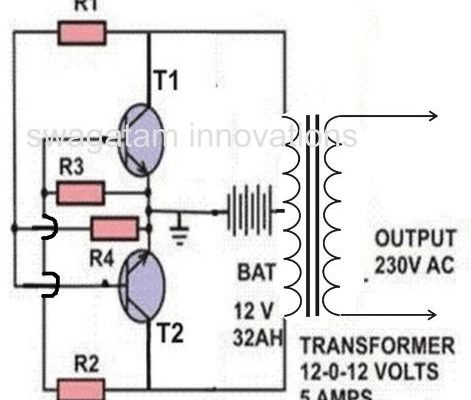
This is most basic way to make inverter with two power transistors. Both transistors are connected cross-coupled, meaning they switch ON and OFF one by one without any extra oscillator IC.
This design is good for learning how transistor inverter works. It uses very less parts and center-tapped transformer.
If you want to see how this simple transistor switching works, check complete circuit and details here:
Simple Cross-Coupled MOSFET Inverter Circuit
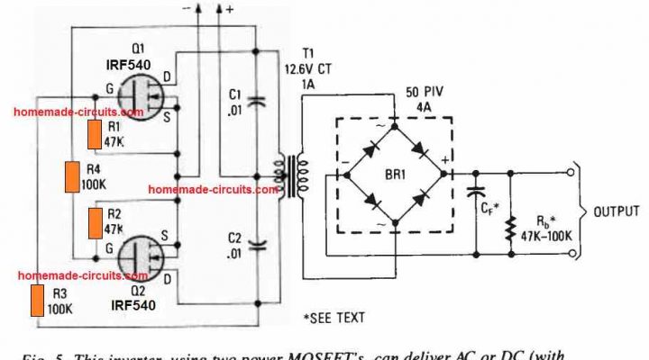
In this circuit, we use MOSFETs instead of normal power transistors for switching. Cross-coupled connection is same, but switching parts are changed to MOSFETs.
MOSFETs are very common in power section because they can handle high current easily if circuit design is correct. This circuit helps to understand how same cross-coupled idea works with MOSFETs.
Read complete circuit here:
Simple Inverter Circuit Using IC 4047
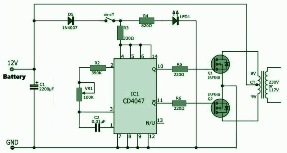
IC 4047 is very useful chip for making inverter oscillator. It gives two square wave outputs from opposite sides to control push-pull inverter stage.
Best thing is we do not need to build extra transistor oscillator to make switching signals. IC 4047 does timing job, and external transistors or MOSFETs handle transformer load.
This is good design if you want inverter using special oscillator IC.
Read complete circuit here:
Simple Inverter Circuits Using CMOS ICs 4049, 4011, 4093 and 4060
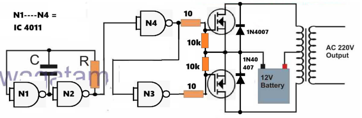
We can also make inverter oscillators using different CMOS logic ICs. This article shows ideas using IC 4049, IC 4011, IC 4093 and IC 4060. These ICs can be set up to make timing signals, which can drive external transistor or MOSFET power stage.
Interesting thing is we can try different CMOS ICs to get switching pulses. Every IC has different internal setup and working style. So if you have these CMOS ICs in hand, you can check these designs in detail article.
Read complete circuits here:
Simplest 100 Watt Inverter Using BJT Astable as the Oscillator
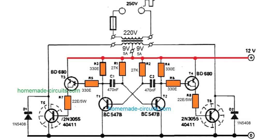
This design uses separate BJT astable multivibrator circuit to make switching pulses. These signals are used to run power transistor stage connected to transformer.
Main idea is making oscillator part using normal transistors instead of one oscillator IC. This design is made as simple 100 watt inverter test. But real output power depends on transformer, battery, transistors and how you build it.
You can check full schematic and part details in this article.
Read complete circuit here:
Which Type of Simple Inverter Circuit Should You Choose?
If you are confused which one to select, check this table:
| Inverter Design | Main Switching Method | Main Feature |
| Cross-coupled transistor | Two power transistors | No separate oscillator IC |
| Cross-coupled MOSFET | MOSFET switching stage | MOSFET-based power switching |
| IC 4047 inverter | CMOS oscillator IC | Complementary timing outputs |
| CMOS IC inverter | Logic IC oscillator | Different oscillator options |
| 100 watt BJT inverter | BJT astable multivibrator | Separate transistor oscillator |
What Should You Check Before Selecting an Inverter?
Before building any inverter, first decide how much output power and battery voltage you need.
For example, small inverter for running small lamp needs different transformer and power stage than inverter for heavy load.
Transformer is also very important. Primary winding must match battery voltage and inverter switching setup. Secondary winding must give correct AC output voltage and current.
We must also check switching frequency, transistor or MOSFET rating, heatsink requirement and battery current.
One more important point is output wave. Most simple circuits here are basic square wave inverters. Do not think they are pure sine wave unless proper filter or SPWM part is added.
Lastly, never select circuit just by seeing big wattage claims. Battery, transformer, switches and wires must handle full load safely.
How to Choose the Right Transformer VA Rating
Many people make mistakes while selecting the transformer for these simple inverters. If you use a small transformer for a heavy load, then it will get very hot and burn out.
For 50 Watt to 100 Watt Output: Use a 9V 0 9V or 12V 0 12V transformer with at least 3 Ampere to 5 Ampere current rating.
For Higher Loads: If you want more power, then you must use heavier wire in the transformer primary winding and bigger MOSFET or transistors on a proper aluminum heatsink.
Matching Primary and Secondary: Always check that primary side matches your battery voltage (like 12V) and the secondary side gives the correct AC voltage according to your country standard, like 220V or 110V.
Common Troubleshooting Tips
If you build the circuit and it is not working, then check these common things first: Check Battery Voltage: Sometimes battery is low or discharged so the oscillator will not start switching.
Check Transistor or MOSFET Pin: Wrong pin connection can instantly destroy transistors or ICs. Double check base, collector, emitter for BJTs, or gate, source, drain for MOSFETs.
Check Oscillator Working: If you are using IC 4047 or CMOS ICs, then check if the timing capacitor and resistor are connected properly to create pulses then. You can check the output pins using a multimeter or small LED.
Transformer Wiring: Make sure the center tap is connected to the positive battery line (or negative depending on the circuit design) and the outer end go to switching devices. Wrong transformer wiring will not produce any AC output.
Important Safety Rule While Testing Inverters
High Voltage Danger: transformer secondary output gives 220V or 110V AC. This voltage can give a severe electric shock or fatal injury. Never touch live transformer output wires with bare hand while the circuit is switched ON.
Use Fuse Protection: Always connect a proper fuse between the battery and the inverter input circuit. If there is a short circuit, then the fuse will blow and save your battery and transistor from burning.
Heatsink is Compulsory: Power transistors like 2N3055 or MOSFETs like IRF540 will get very hot during operation. Always bolt them to a good aluminum heatsink using mica washer and insulating paste.
Conclusion
We can make simple inverter circuits in many ways using normal transistors, MOSFETs and CMOS ICs.
Some designs use cross-coupled transistors for direct switching, while others use IC 4047 or other CMOS ICs for oscillator signals.
These five inverter designs give different options to try basic inverter building.
You can check individual articles for circuit diagrams, parts lists and working details. Select design based on your battery voltage, power need and parts you have.
Always check full circuit and parts rating before connecting battery and transformer. AC output can give heavy shock, so use proper insulation and safety during testing.

Questions & Answers
Hello kind sir! Information shall be free (hopefully!)
Would you direct me please, I have 2 sets of 3 x 40volt / 6.0Ah lithium batteries (different battery systems), all new batteries, all from outmoded tool lines.
I would like to make a single inverter for the 6 batteries together, or 2 inverters, one for each set of three batteries. My design should prevent excessive current draw, and warn, then shut off as the lowest battery in the group reaches 15% SoC (state of charge,) to prevent battery damage. Ideally, the inverter could output 120 & 240 VAC, and have surge and over/undercurrent protections on the AC outputs. Ideally, I could also include DC out for USB Type A & C, also with protections as above. The AC outputs need a clean sinusoidal waveform; appropriate filters should be in place on the DC outputs.
That’s not much to ask, right? But seriously, thanks for your help, this page is already a brilliant resource! For my project, which of the designs would be a great place to start?
Hello Rod, I will surely help you with this project, can you please confirm, if your input DC to the inverter would be 40V/18 Ah for one inverter, and the same for the other inverter also? And should the inverter be a sine wave or a square wave…??
I wanted an inverter diagram that can produce pure sinusoidal wave at AC not square waves, can you help me with that?
Sure can try the following concepts:
https://www.homemade-circuits.com/arduino-pure-sine-wave-inverter-circuit/
https://www.homemade-circuits.com/sg3525-pure-sinewave-inverter-circuit/
hi sir…pls apart from generators,turbines or solar panels is there any other way to generate at least 12v power source reliably?
Hi Md, I think you can generate good electricity through road speed breakers…
https://www.homemade-circuits.com/generating-electricity-from-road-speed/
pls sir I just the one of the diagram specifically fig 2 using cd4047 one of the transistor is very hot and one is not working although no output
what you is wrong because I use my meter and check there’s voltage flowing through the gate
Okon, I think your MOSFETTs are blown, or maybe not good.
Please remove the MOSFETs and initially try with BJTs, such as TIP122 and check the response…
With BJTs make sure the base resistor is above 1k….
Hi Swagatam
Im looking at building a 200W inverter (12V -> 240VAC).
However, 9-0-9 10A transformers are difficult to get in UK.
I can however get 12-0-12
https://uk.farnell.com/multicomp-pro/mcta250-12/transformer-toroidal-2-x-12v-250va/dp/9530720
Ideally I’d like to include over temperature as well as low battery.
Would it also be possible to arrange a circuit that would allow charging of a 12V 80Ah battery using the same transformer ?
I have emailed you
Hi Paul,
With a 12V transformer, when your battery voltage drops to 11V, the AC output from the transformer could drop to 200V or lower, that is why a 9V transformer is recommended.
Yes, an automatic charger can be included using the same transformer through relays, as discussed in the following article:
https://www.homemade-circuits.com/single-transformer-inverterchargerchang/
Respected Sir
I am refering to the inverter circuit (Using IC 4060). This circuit is decently made using only one output but the query is that can we use all the outputs or maximum outputs using 1 or 2.2 or 10 meg resistance??? Obviously not disturbing it’s oscillation.
Please help.
Dhananjay, All the outputs of the 4060 IC generate different frequencies, so you can select any one of them which matches the frequency of your inverter.
l designed a simple power supply using rectifier diodes 1 n4001, 25v 470 uF Cin,7815 voltage regulator,470 uF 16 v Cout, and 220/24 vac transformer to power your simple ups battery charging circuit.
But it failed to power an already made 12 vdc/220 vac 300w ECCO inverter.
the input capacitor burned.
so what can be the problem and solution.
Please comment under the same article which you are referring to and please specify the circuit diagram also, I will try to help!
you’re doing great! Could you please help me with the circuit of 4KVA inverter
Please provide the detailed specifications of the inverter, i will try to figure out…
I tried the one with ic 4047 using irfz3205 but after I while one stopped working and the gate resistor started heating up before this the mosfet what making noise not really audible but when I get close I could hear it and also when only one side was working I only loaded the CRT with 15watt bulb and the second mosfet went of Total what can be the cause??
although I used a 1.2amp 12.0 12 transformer
It seems like the MOSFETs are not good and have some internal defect, or maybe they are not original devices.
You can try using BJTs instead and check the response. Any power BJT such as TIP122 should work.
If BJTs work normally, then the problem is certainly with your MOSFETs.
Hello sir I wish to know you better. You’re a great inspiration to me .
In the inverter made by using cross-coupled transistors, why the two 2N3055 transistors don’t conduct together? Can you please give a more in-depth and technical explanation?
the two 2N3055 transistors don’t conduct together because the characteristics of no two transistor or inductance of the winding can be 100% identical, therefore one of the stages will start before the other, triggering the oscillating action.
Thanks for answering, I’ve one more question will it still oscillate and produce ac signal without the base emitter resistors?
It will oscillate even without the base emitter resistors.
hello buddy, how are you doing today,am asking whether I can use an audio transistor in an inverter?
You can use any type of transistor in an inverter circuit, just make sure the current and voltage ratings match the inverter battery/transformer specifications.
Hello Swagatam, if I use any of your inverter circuits here with a 500watts round transformer. Then use 14pcs of mosfets that is 7pcs each on both sides. Then use it on a 200ah 12v battery. Can it work sufficiently or I reduce the number of mosfet?
Thanks.
Hello Morris,
Yes, it will efficiently without any issues. You can use IRF3205 MOSFETs
good day boss.
can this project power tv and fan
thank you sir
Yes, the inverter designs can be used to power TVs and fans
Hello Swagatam. For the Cross Coupled MOSFET Inverter, I could not find a value for the capacitor designated as Cf at the output.
Hello Simon, the Cf can be a 100 uF / 400V filter capacitor.
Thank you
Hello, can I change the 2N3055 transistor to any other transistor like 2sc5200.
Thanks.
You can try 2SC5200, but it won’t be as efficient as 2N3055, because it has a high VCEO of 230V…this should be below 100 V.
Thanks
In number 3) circuit diagram below
Which number of resistor and capacitor can I use to generate clean 60hz
I think roughly it is 0.01uF and 100K, but you will have to use a frequency meter to adjust it accurately.
On the push pull inverter circuit are the gates on each set of mosfets joined together, the lines appear to be missing on the circuit. Thank you,
Yes all the gates of the mosfets on each group are joined together.
Am from Nigeria I made the astable multivibrator circuit using transistor, resistor, capacitor and mosfet but the problem is that one mosfet burn and the other mosfet just continue working but what surprised me is the despite one mosfet working and the other burnt the circuit still workes but I don’t know why
Can you please provide the link of the circuit diagram?
I built the cross coupled using 2n3055 power transistors. Working perfectly…handy and reliable it is.
Thank you for trying this circuit, glad it is working!