In this post I have explained a simple wheel rotation identifier or detector circuit which can be used for ensuring a continuous rotating movement of a concerned wheel through an LED, photodiode arrangement. The circuit was requested by nzb109.
Technical Specifications
I want to generate a trigger circuit to detect that a WHEEL is stationary. The wheel has slots on its periphery.
There is a LED transmitter in front and a photodiode behind the wheel.
As the wheel rotates and the slots come in front of the LED and then pass by, there are pulses recorded by the photodiode.
When the photodiode comes to rest with the slot in front of LED, there is continuous DC signal output.
The difference between motion and stationary wheel appears as a pulse train and continuous DC respectively.
Based on this, how can I design a trigger mechanism that discriminates between pulse train and Continuous Dc and triggers on only due to the continuous signal?
The Design
The proposed wheel rotation detector circuit may be understood with the help of the following explanation:
Basically it's an optical encoder circuit which can be can be divided into four stages: the first being the photodiode detector stage consisting of PD, T1, the second amplifier stage encloses T2 section, the third stage is an inverter stage which inverts the response from the preceding two stages, while the last stage forms the relay driver stage for executing the relay activation.
As long as the wheel rotates, the photodiode PD responds to the alternating lights through the wheel slots and generates correspondingly pulsating voltage across T1 base emitter.
The above response from PD charges and discharges T1 alternately such that T1 conducts with the same sequence as the PD. This ensures that T1 maintains quick switching relative to the wheel rotation which is in turn amplified by T2 to a level which keeps T3 switched ON firmly as long as the wheel rotates.
With T3 switched ON, T4 is inhibited from the required base voltage keeping it switched OFF and the connected relay.
Now in case the wheel ceases to rotate and becomes stationery, the PD is subjected either to a continuous light from the slot or no light at all if no slot coincides with PD.
In either case, the PD stops generating the pulsating voltage required to keep T1 conducting.
With T1 no longer able to conduct results T2 and T3 also in a non-conducting state which instantly prompts T4 to switch ON via R5 and consequently the relay is also switched ON, indicating a permanent halt of the wheel.
Circuit Diagram
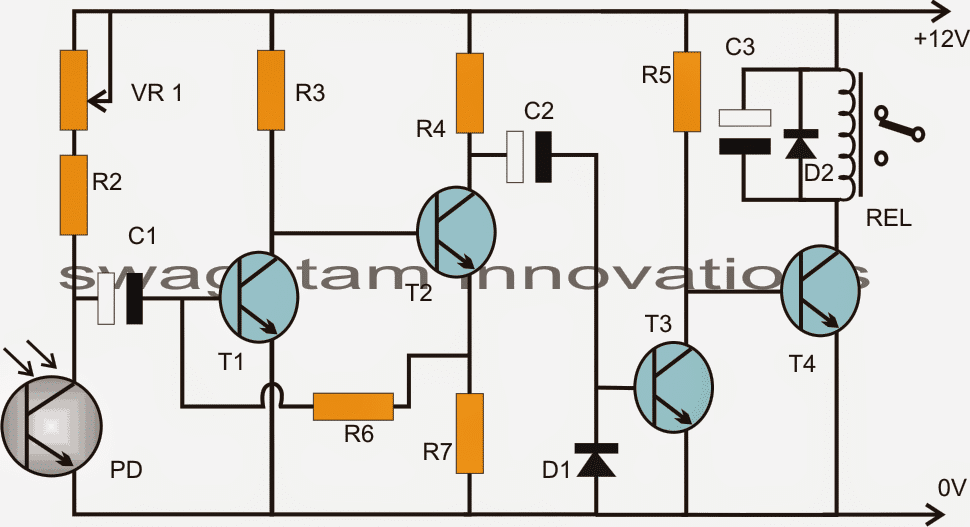
Parts List for the above wheel rotation detector circuit
R2 = 470 ohms
R3 = 47K
R4 = 1K
R5 = 10K
R6 = 100K
R7 = 330 Ohms
VR1 = 100k preset, for adjusting the sensitivity of the photodiode
T1---T4 = BC547
C1 = 2.2uF/25V
C2 = 4.7uF/25V
C3 = 33uF/25v
D1, D2 = 1N4007
PD = photodiode or phototransistor
REL = 12V/spdt/400 ohm relay


Questions & Answers
Ah ha! Finally, I think I understand. Diode D1 acts as a clamping diode, so the entire waveform from T2 is adjusted so that the bottom of the waveform is at 0.6V (assuming that’s the forward drop across the diode). So as long as the waveform passes through C2, the base of T3 will be at or above 0.6V. Once the waveform stops, the voltage at the base of C2 will decay to less than 0.6V. Thus as long as the forward voltage across T3 Base-Emitter is no greater than 0.6V, T3 will be on whilst the waveform is “on” and off when the waveform ceases. So the key seems to be that the natural (ie as in the data book) forward voltage across D1 must be slightly greater than the natural (as in the data book) forward voltage across T3 Base-Emitter. Have I got it yet?
I think the diode actually has no role at all, because is reverse biased. It can be replaced with a resistor also….in fact a resistor would make more sense….the circuit was designed by me a long time ago, but I don’t precisely remember why I put that diode in that place.
If the diode was inverted, meaning the cathode touching the ground, then it would make some sense…I think the diode should be inverted with the cathode connecting the ground line.
I can see how the addition of a capacitor from T3 base to ground would store a charge from the square wave passing through C2. However I don’t see how the basic circuit can work without that extra capacitor. What keeps T3 base high (conducting) without that additional capacitor?
When T2 conducts, C2 will discharge through it, when T2 switches OFF, current from R4 will reach the base of T3 to switch it ON
Hi Swagatam
What will be the behavior of this circuit when the wheel is turning at slow rpm?
sorry, the capacitor must be positioned at the base of T3 after a resistor, not at the base of T4.
Hi Abu-Hafss,
good question!
The relay would also oscillate at that rate unless a suitable capacitor is installed across base/ground of T4 after a series resistor from T3 collector.