In this article I have compiled 10 interesting yet simple LED chaser circuits, which not only create beautiful running light effect but are also easy to build.
These primarily incorporate LEDs as well as mains operated bulbs through triacs. The proposed circuit is transformerless and is thus a lot compact and light weight.
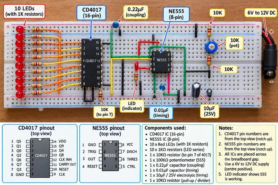
Which LED Chaser Circuit Should You Choose?
In this article you will find different types of LED chaser circuits which can be built using popular ICs like the IC 555, IC 4017 and 74LS164. Each circuit produces a different type of running light effect. The following guide below will help you to select the right circuit for your requirement.
- For a simple running LED effect: You choose the basic IC 555 and IC 4017 LED chaser circuit.
- For controlling more than 10 LEDs: You may choose a circuit using two or more IC 4017 stages, depending on the required LED count.
- For the Knight Rider scanning effect: Grab the Knight Rider LED chaser circuit which produces a scanning light pattern.
- For a fading LED effect: You may go for a fading LED chaser circuit that gradually increases and decreases the brightness of the LEDs.
- For different LED sequencing patterns: You can choose a suitable 74C164 or 74LS164 based circuit.
- For forward and reverse LED movement: You may select the reverse-forward LED chaser circuit designed for this effect.
- For controlling LED lamps or bulbs: Choose a circuit specifically designed for the required load and supply voltage. Check the output driver ratings before connecting the load.
| Your Requirement | Recommended circuit |
|---|---|
| Simple running LEDs | 555 + CD4017 |
| More than 10 LEDs | Two CD4017 ICs |
| Knight Rider scanning effect | 555 + CD4017 with diode network |
| Gradually fading LEDs | LED chaser with transistor stages |
| Different sequencing patterns | 74C164 or 74LS164 |
| Forward and reverse movement | Reverse/forward LED chaser |
Before building any of these circuits, you must always check the supply voltage, component values and maximum output current specified for that particular design.
How Does an LED Chaser Circuit Actually Work?
An LED chaser circuit is a simple electronic circuit which makes a group of LEDs glow one after another. This gives you a running light effect which is used in decorative lights, car lights and many other electronic projects.
A simple LED chaser can be made using IC 555 and IC 4017. The IC 555 produces clock pulses and the IC 4017 uses these pulses to switch its output pins ON one by one. When LEDs are connected to these outputs, then they start glowing one after another and produce the chasing effect.
The chasing speed can be changed by adjusting the resistor or capacitor values connected with the IC 555. Other types of LED chaser circuits use different ICs and components to produce special effects like forward and reverse running lights, scanning lights and fading LEDs.
Below given are different LED chaser circuits which you can try building according to your requirement. Some circuits are simple, while others use more components to produce different types of running light effects.
1) Basic 10-LED Chaser Circuit (555 + CD4017)
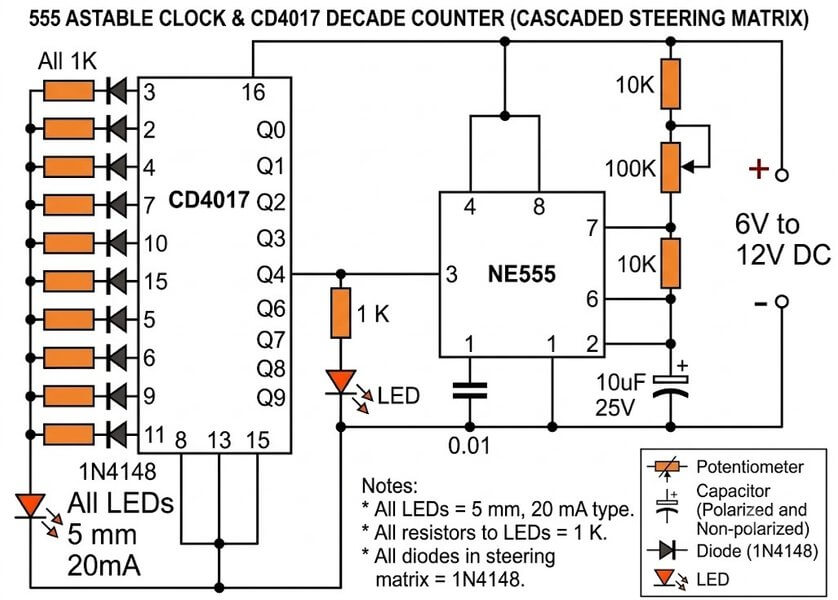
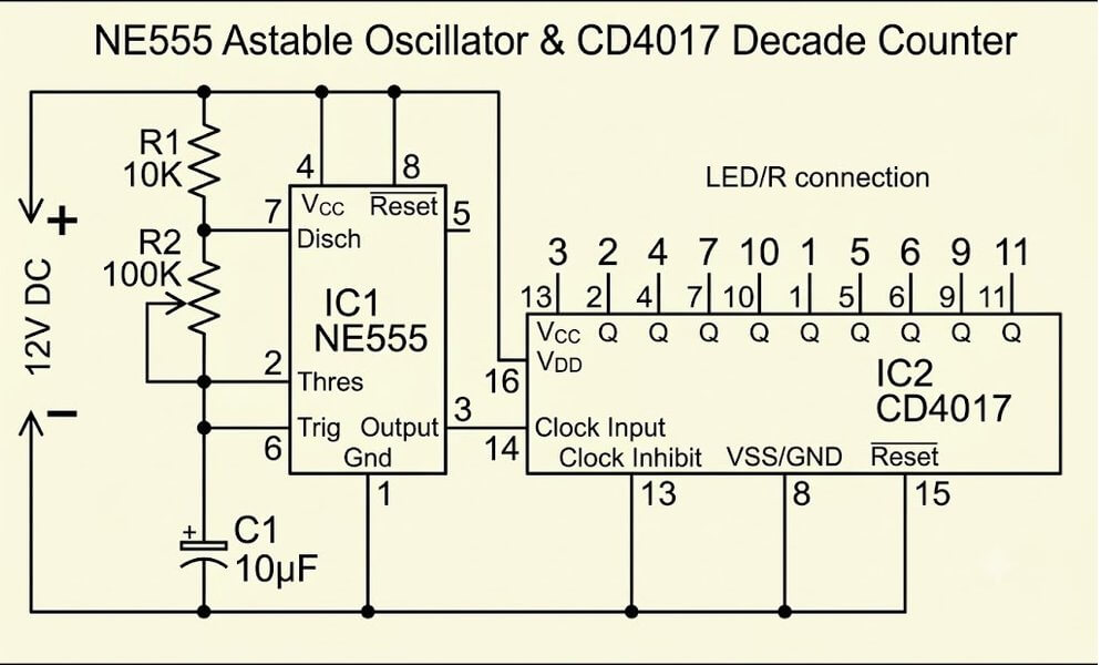
How it works: This is the ultimate beginner-friendly running light project. It uses a standard 555 timer IC wired as a clock oscillator, sending steady pulses directly into a CD4017 decade counter IC. The 4017 takes those clock ticks and turns its 10 output pins ON one by one in a clean, continuous loop.
Main features: You get a smooth 10-LED chasing sequence that works anywhere from 6V to 12V DC. Speeds are fully adjustable—just turn the 100k speed control pot to speed up or slow down the running effect. LEARN MORE...
2) 18-LED Cascaded Chaser Circuit (Dual CD4017)
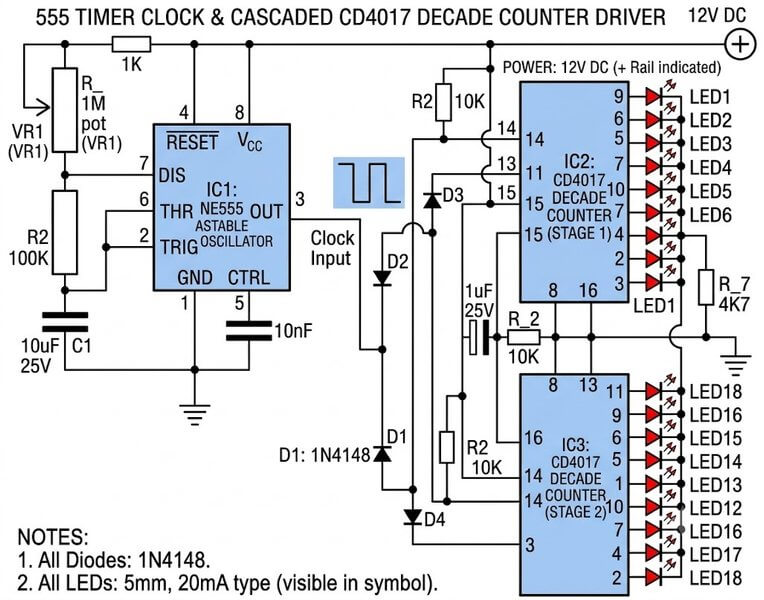
How it works: A single CD4017 chip can only handle 10 steps, but when you need a longer running line, you can link two 4017 ICs together.
The 555 timer provides the main clock heartbeat. Once the first 4017 finishes counting through its pins, it passes the duty over to the second IC.
Main features: Uses a few steering diodes hooked between the two counter chips to handle the handover logic seamlessly.
This lets you run 18 LEDs sequentially without needing microcontrollers or writing software code.
3) 100 to 200 LED Forward-Reverse Chaser (Diwali & Christmas Decorative Lights)
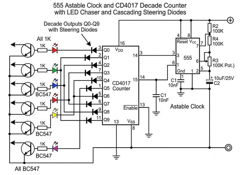
How it works: Basic chasers are fun on a breadboard, but festive lighting for Diwali or Christmas demands a lot more power and bigger arrays. This circuit expands standard sequencing by adding heavy-duty transistor driver stages.
Main features: Instead of just cycling in one boring direction, the lights travel forward to the end and then reverse back toward the start. Depending on the power supply and transistor setup, you can hook up massive strings from 100 up to 200 LEDs. LEARN MORE...
4) Dual-Mode LED Chaser with Flashing Blinker Effect
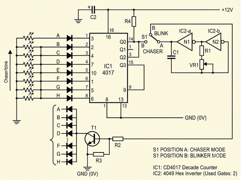
How it works: Designed to answer a popular reader request: having one circuit that can chase and flash. It combines together a standard running sequencer with a master bypass line connected to a selector switch.
Main features: Flip the toggle switch to mode one and the LEDs run sequentially one after another. Flip it to mode two, and the chasing stops while all LEDs begin flashing together in a full-bank strobe effect. LEARN MORE...
5) Center-Out Outward Chasing LED Circuit
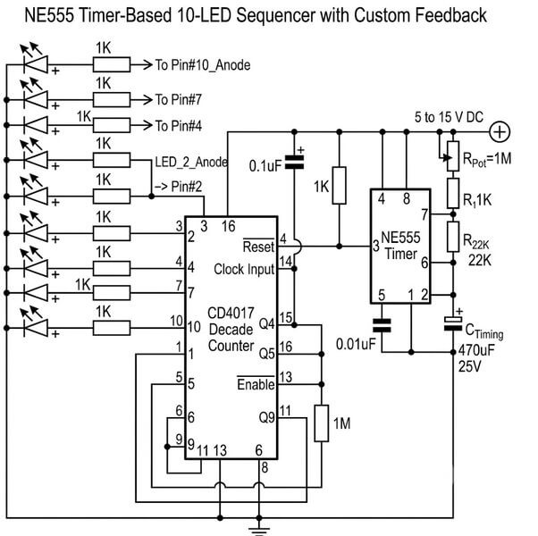
How it works: Most chaser designs move left to right, but this setup changes the visual routine entirely.
By cross-wiring output pairs from the middle of the LED strip outward, the lighting starts right at the center.
Main features: As clock pulses arrive, the light bursts symmetrically outward toward both ends at the same time.
It gives a striking spreading-light effect that looks great on custom display signs and automotive panels. LEARN MORE...
6) KITT Scanner Knight Rider LED Chaser
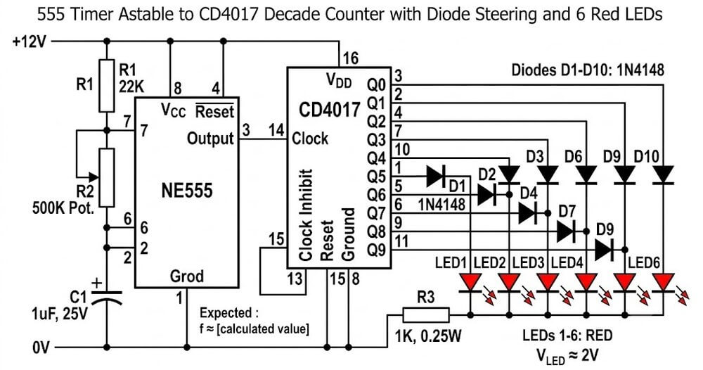
How it works: Inspired by the iconic scanning red light on the front of the KITT car from Knight Rider. It pairs the trusty 555 timer and 4017 decade counter with a simple matrix of 1N4148 signal diodes.
Main features: The diode matrix routes output pulses so a group of 6 LEDs lights up back and forth in a smooth, continuous scanning motion.
No programming needed...just pure hardware logic. LEARN MORE...
7) Slow Adjustable Fading LED Chaser Circuit
How it works: Standard digital chasers snap LEDs ON and OFF instantly. If you want a softer, more elegant look, this circuit places discrete BJT transistor stages and charging capacitors at each LED output.
Main features: As each output triggers, the capacitor charges and slowly fades the LED up, then slowly discharges to fade it down.
This creates a smooth, gentle lighting transition ideal for mood and decorative displays. LEARN MORE...
8) 8-Bit Shift Register LED Chaser (74C164 + 4011)
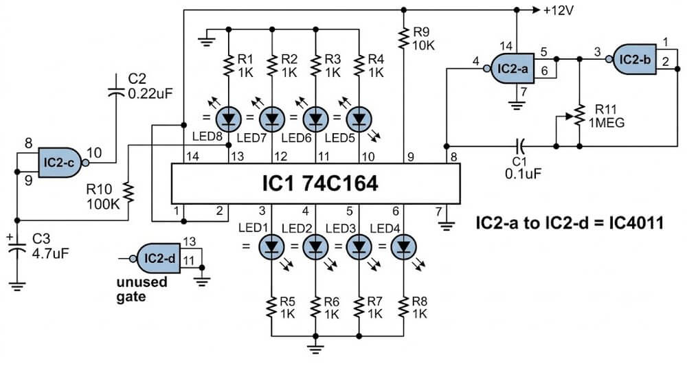
How it works: An alternative way to build a running light display without using a 4017 counter. It uses a 74C164 8-bit shift register IC paired with a 4011 quad CMOS NAND gate IC acting as the clock pulse generator.
Main features: Shifts a bit across an 8-LED sequence continuously.
An RC network on the reset pin makes sure the board clears its memory and restarts the cycle cleanly every time it hits the 8th step. LEARN MORE...
9) Dual 74LS164 Center-Meeting LED Bar Chaser
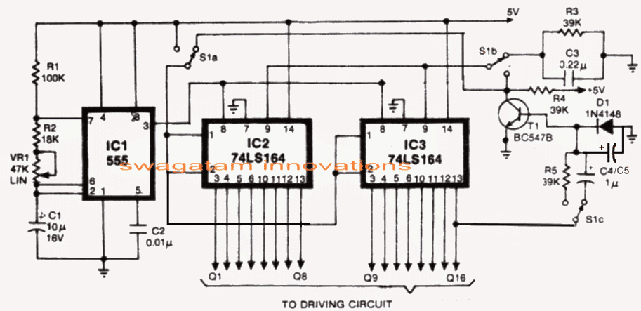
How it works: An advanced shift-register circuit built with two 74LS164 ICs and a 555 clock timebase. The logic is wired so that bits shift inward from opposite ends of the display board.
Main features: Two glowing light points start on the outer edges, travel toward each other, and meet right in the middle.
A quick transistor reset stage then clears the line so the cycle can start over. LEARN MORE...
10) 16-Step Bidirectional Chaser Circuit (IC 40193 + IC 4514)
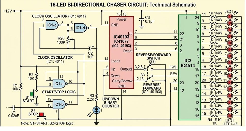
How it works: For high-step sequencing without microcontrollers, this setup replaces the 4017 with a 40193 up/down binary counter and a 4514 1-of-16 decoder IC.
Main features: A simple NAND gate latch handles direction changes automatically.
You get a full 16-step forward-and-reverse running sequence with total stability and no programming required. LEARN MORE...
Common Problems in LED Chaser Circuits
Sometimes an LED chaser circuit may not work properly after building it. So following are some common problems and the things you can check.
Fault#1: LEDs are not glowing
First check the power supply and make sure the positive and negative connections are correct. Also check the IC pin connections, LED polarity and any loose wires on the circuit.
Fault#2: All LEDs are glowing together
Check the wiring of the IC outputs and make sure the LEDs are connected according to the circuit diagram. A wrong connection can stop the normal chasing action.
Fault#3: LEDs are chasing too fast or too slow
In circuits using an IC 555 timer, the chasing speed depends on the timing resistor and capacitor values. Check these components and adjust them according to the circuit design.
Fault#4: Some LEDs are not glowing
Check the polarity of those LEDs and inspect their connections. Also check whether the required current limiting resistors are fitted correctly.
Fault# 5: The circuit works for some time and then stops
Check the power supply voltage, loose connections and any components that may be overheating. If transistors are used to drive many LEDs, you make sure they are not being overloaded.
Always disconnect the power before checking or changing any wiring. If the circuit operates from mains electricity, do not touch the circuit while it is connected to the supply.
How you can Add more Number of LEDs in a Chaser Circuit?
Sometimes you may want to connect more LEDs to a chaser circuit than what is shown in the diagram. This is possible in some circuits but the method will depend on how the circuit is designed. For example the IC 4017 has 10 decoded outputs, so it can control 10 chasing steps in its normal arrangement.
Now if we want more steps then we may need to add another IC 4017 and connect it nicely with the first IC. So just connecting more LEDs to the same output will not increase the number of chasing steps.
In circuits which uses shift register ICs we can also add more ICs to increase the number of LEDs in the sequence. But the extra connections you must do correctly for the circuit to work as expected.
We must also check the power supply current. When more LEDs are added then circuit may need more current. If the IC output cannot supply the required amount of current, we may have to use extra transistors to drive the LEDs...
So before you add more LEDs, first of all you have to check the circuit diagram and the IC output limits, do not simply connect extra LEDs without checking the current, or else the IC or other components may get damaged.
Which is your Favorite LED Chaser?
So guys, that's it! These were a handful of interesting and cool LED chaser circuit designs and compilation, which provides you with varied options of creating your own LED chasing effect without depending on any microcontroller ICs. So which one did you like? Do let us know in the comment section, and if you have any issues with the circuits, do not hesitate to ask them through your comments.

Questions & Answers
sir,do u have single time LED Chaser after stop.and glow single LED >?
Bhavin, I could not understand your requirement….please explain it elaborately…
sir,need circuit diagram one time LED chasing after stop chasing
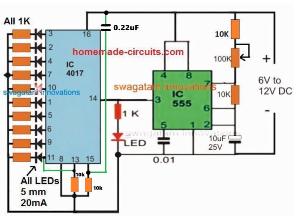
Bhavin, if you want the LEDs to illuminate sequentially only once, and then stop with one LED lit up, you can try the following circuit, see how pin#13 and pin#15 are configured:
in this diagram last 11 no pin glow and 14 no pin blinking
Yes, that will happen, because one full chasing sequencing stops at the last pin11, as you wanted. You can remove pin14 LED, if you don’t want it…
I want to make a round LED chaser circuit. It will be placed around the doorbell switch
You can remove LEDs on pin11 and pin14, if you do not want them…
no of led increase 18 then what will circuit diagram
use the 74LS164 based circuit.in this solution how many led operate in single ic
8 LEDs on one IC:
https://www.homemade-circuits.com/led-chaser-circuit-using-ic-74ls164-leds-illuminate-in-bar-mode-then-shut-off-together-or-one-by-one/
please share circuit diagram
It is given under 4) LED Scanner Circuit Mustang Type, in the above article…
sir,planning change in circuit.LED chase once after all LED are glow.please share circuit diagram
4017 circuit cannot easily modified for LEDs to glow all together after one chase, for that you may have to use the 74LS164 based circuit explained in the above article…
You can try this:
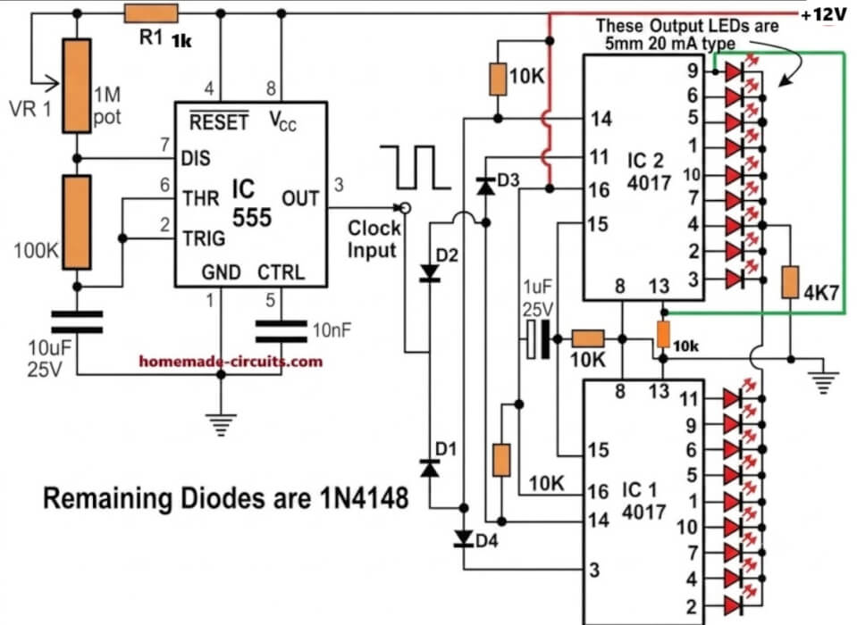
love your 18 chaser light circuit only problem it needs to run on 1.2v dc i want
to use on my solar light i have in my yard that failed. it is a 8 pin single ic that
runs all 18 leds. so your circuit peaked my interest. the original 8 pin ic i cant
see any numbers on it to maybe replace it. so im looking at your circuit with
the 555 and a pair of 4017. any thoughts on what to do?
gary
I am glad you found the circuit interesting, however the IC 4017 and 555 cannot work with voltages below 3V, so 1.2V seems too low for them to operate correctly.
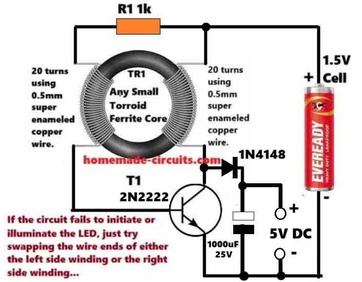
You caan do one thing, boost the 1.2V to maybe 5V and see if the 18 LED circuit works or not.
For the 555 IC please replace it with IC 7555 or LMC555 versions.
For bosting 1.2V to 5V, you can try the following circuit:
Hi Swagatam,
First, thanks for all your efforts.
I have doubt, may be a silly one. In the 18 LED light chaser circuit, how long can I expect the circuit to function efficiently, that is without the battery getting heated or the LEDs getting burnt out. Is it safe to use the same circuit with the mentioned components as I would like to build it for a school project?
Thanks in advance.
Thanks Uma,
There’s no way the circuit can degrade or LEDs burn as long as the DC supply is as per the design specifications…It can keep on working efficiently practically forever..
Yes, it is 100% safe to use the design as exactly shown in the diagram with the indicated supply voltage DC.
You can surely build it for your school project, and let me know if you have any issues with the working of the circuit..
I was hoping to see the dual 4017 knight rider circuit in action, but the link did nothing. Do you have a video of the fading effect also?
Thanks.
which link are you referring to??
Hi
Swagatam finally got to work on the modified chaser circuit found a error on my side the leds flash now after they go through a sequence then latch then the whole array flash a couple of times but they won’t reset just stay static as if the tip122 is keeping them lit and won’t reset if I disconnect the 1uf cap at pin 9 of the 4017 the led will reset but not flash connecting this cap back the leds will flash but not reset
would you have any ideas
regards
Thank you Sparks, glad to know the LEDs are doing are sequencing and flashing as required.
It seems like the capacitor is leaking current to pin#13, that is why it is getting permanently latched.
Please replace the pin#9 capacitor with a 1uF non-polar capacitor, and the associated 100k with a 1M.
And now check the difference.
Hi swagatam
Thanks will let you know how I get on
regards
Sure Sparks, no problems!
Hi Swagatam
The lights do not flash after the last count and do not reset when I connect the supply the 4017 Counts but will not flash or reset eg LEDs will stay illuminated
regards
Thanks Sparks, please do the following modifications:
please connect pin#15 to ground through a 10k resistor, and connect a 0.1uF between the positive supply and pin#15, this will ensure the sequencing always starts from pin#3 onwards whenever the circuit is powered ON..
Use a non-polar capacitor 1uF for the pin#9 of 4017.
Disconnect the base of TIP122 from the collector of the BC547.
Now check how the LEDs respond. Tis will confirm the basic work of the circuit as per the following concept:
https://www.homemade-circuits.com/sequential-bar-graph-turn-light/
Please let me know the results…
hi Swagatam
I have already taken the bc547 emitter to pin 1 but what is strange is that it will start sequencing but for some reason will not reset and will not flash at the end of the cycle it works ok using the original circuit but I am having problems with the modified circuit to get it working as it should
reqards
Hi Sparks,
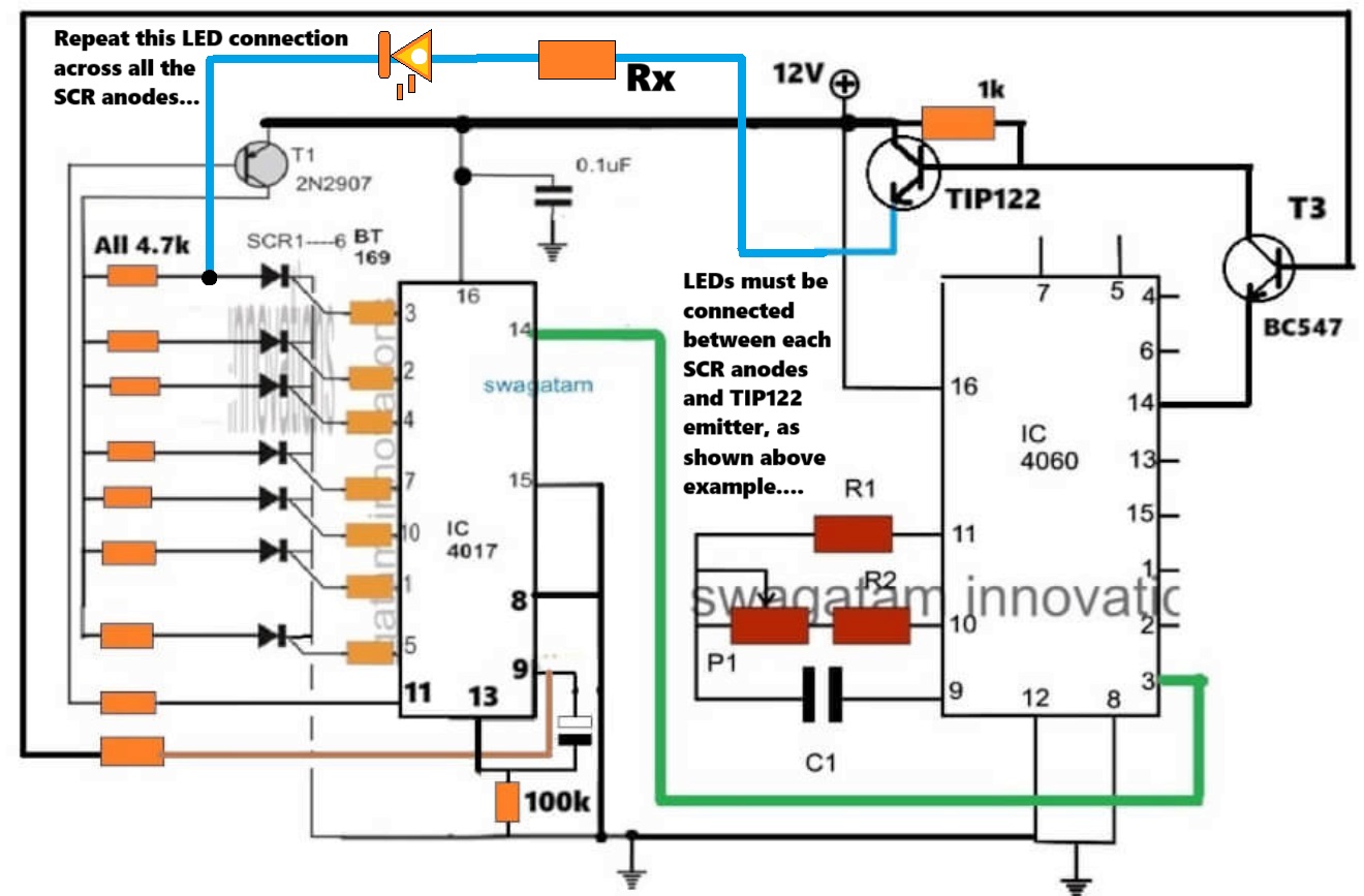
You said that the 4017 circuit stage works correctly and the LEDs illuminate sequentially and also reset normally to repeat the process when it is tested as a standalone circuit. So can you please tell me in what situation does this normal working stops, meaning with which circuit connection does this normal functioning gets disturbed and stops?
hi swagatam
thank you for your quick reply if I leave the emitter open and say connect the led to the 2n2907 collector and to to scr anode the led will be lit and reset and.start the sequence but when I connect it to the tip122 emitter the led will be lit (but not reset or flash the leds )
reqards
sparks
Hi Sparks,
please connect the emitter of the BC547 with pin#1 of IC 4060 to slow down the flashing effect.
The scrs should turn off once the 4017 sequence reaches pin#11. Because at pin#11 2N2907 turns off so there’s no holding current for the SCRs, and since the LEDs are flashing that means these would also cut off current at one instant, which would mean all SCRs latch breaking off due to the complete absence of anode/cathode current and gate current, so at this moment the SCRs would turn off.
Please let me know.
Hi swagatam
A while back you did me modified circuit of.the sequential led array light circuit (that worked ) Then you designed so all the led I am using all flashed at once then reset but I have build it and cannot get it to work you said connect load to Tip122 and anode on scr but the lights stay on plus they no ref to ground
the transistors Tip122 and 2n2907 are both at +voltage
hope you can help
reqards
hope
Hi Sparks,

Yes, I think you are referring to the following circuit idea.
We will have to check and diagnose the circuit step wise.
Initially can you please tell me how the LEDs respond without the TIP122 emitter connected (open)?
BUEN DIA Y CORDIAL SALUDO
DESOHACER UN LETRERO LUMINOSO CON MAS DE 100 LEDS Y ME GUSTARIA CONOCER ESQUEMAS QUE ME PERMITAN ESTO USANDO POCOS ELEMENTOS, TALES COMO:
LEDS
RESISTENCIAS
CAPACITORES
TRANSISTORES
OTRS ELEMENTOS QUE CONSIDEREN INDISPENSALES
Sure, you can try the following circuit design. You can put 4 LEDs in series on each transistor collector arm, adjusting the series resistor value accordingly:
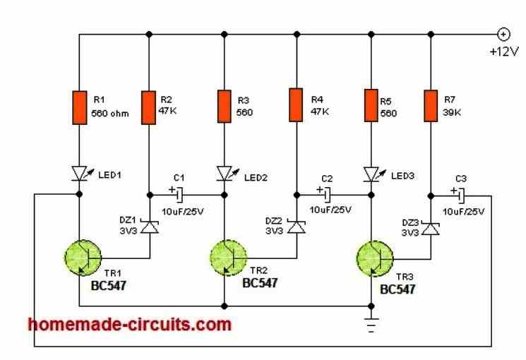
Hi Swagatam, I built the outward chasing LED circuit No:9 by connecting all the parts as shown in your diagram. But my circuit is not working. Capacitor value is shown as 470uF 25V. Is it correct? Can you please assure me that there is no error in the circuit diagram?
Hi Mahesh,
There’s no error in the outward LED chaser circuit configuration, except the IC 555 part values. Please change them to the following values. Replace the 1M pot with 100k pot, 22k resistor with 100k resistor, and 470uF capacitor with a 10uF/25V capacitor. Also, please replace the 555 pin#3 1K resistor with a 10k resistor.
Goodmornig Sir. In the Knight Rider Chaser schematic it mentions 10x1n4008 diodes but only 8 of them are visible. Maybe they go on outputs d1 and 3 of the 4017?
Thanks
Good Evening Rosario,
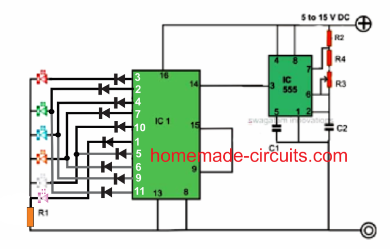
I think the diodes needs to be configured in the following way, if 10 diodes are used:
Hi Swagatam,
In the circuit 16 LED Reverse/Forward Chaser Circuit, if I wanted to use only 14 LED, omitting the last 2, would the circuit continue to function normally?Best Regards.
Nélio.
Hi Nelio,
Yes, if you do not use the last two inputs the circuit should still work normally, according to me.
But since this circuit is not designed by me, I am not entirely sure about its functioning and whether it will successfully work or not, and also I am not well-versed with those ICs.
In your circuit No. 6 – 18 Led chaser circuit If I want to use 3 mm Led
then what changes should I Do ?
No need to change anything in the design, you can use the same circuit design without any changes….
Hi Swagatam,
I have had a look through the prior projects and experiments and could not find a suitably matched project for my needs.
I need to build a circuit that makes 3 or 4 LEDs “breathe” – fade in/ fade out over 2 to 5 seconds. There is a FADE IN/OUT Arduino project in the library but I do want to incorporate Arduino for this setup. I read about using 2 NE555s set slightly out of phase and the pulsing would be equivalent to the beat frequency of the output. The article lost me when it was suggesting XORing the output to the LEDs. Does this make sense to you? How would you do this? Or would you do it differently?
Thanks
Thank you Michael,
Did you check the following article?
https://www.homemade-circuits.com/alternate-onoff-led-fader-circuit/
I think this circuit should be able to fulfill your requirement.
A 5 seconds timer can be added through additional BJT circuit stage.
Please let me know if there’s any specific thing missing in the design.
Alternatively, a single 4093 IC could be also used to get all the required feature from a single chip.
Thanks for this. It’s virtually perfect as is. Any ideas how to make the LEDs brighter. It looks like the highest voltage through them is around 5v. Do you think I could safely bump the input to 19v? What is the BJT circuit?
Cheers
Sure, the LED brightness can be adjusted by adjusting the values of the R6 and R7 resistors.
The IC can work with up to 32 V, so 19 V can never be an issue. Just make sure the voltage rating of C1 and C2 capacitors are at least 1.5 times of 19V or higher. The R6, R7 must be appropriately calculated so that the current does not exceed their max specifications.
The transistors T1 and T2 are the BJTs, and form the BJT circuit.
Hello, Swagatam!
First, THANK YOU for having this website! It’s very generous to do this 🙂
I’m very interested in Circuit #1 and Circuit #5, because those look like something I can actually do and my goal is that I want something I can fit into a sort of “shadowbox greeting card” to be mailed to people.
My question is:
Since I’m looking at either the TLC551 or the LMC555, which as far as I can tell operate a 1V and 1.5V respectively, which values do I need to recalculate to run off of a 3V battery? Or is that not even do-able? I can go up to 6V, because I’ll be using CR2032 button cell(s) and minimal holders.
I’ve been looking, and asking, for the answer of how to go from a 5V-NE555, to a 1V or 1.5V CMOS-555 for three months – no exaggeration! -, but I still have no idea at all what values I need to recalculate to adjust the circuit from the NE555 to the CMOS low-power 555 or 551 IC.
If you could tell me what to recalculate, that would be a huge kindness! Not even do the calculations, but only tell me which things need to be recalculated, would be a big help!Even if I still need 6V but maybe only need to add a resistor to not “blow out” the CMOS timer, if you could tell me that, it would be a major kindness to me!
Thank you!
Hi Kris,
Thank you so much for liking this website, glad you found it useful.
If you check the datasheet of the cmos 555 ic it shows a formula for calculating the operating frequency which does take the supply voltage into account.
https://www.homemade-circuits.com/cmos-ic-lmc555-datasheet-works-with-1-5-v-supply/
That means regardless of the supply voltage the resistor capacitor values can remain the same.
So you can feel free to use the same circuit configuration which are shown in the above article for your specificapplication.
I think a 3V battery supply would be more appropriate instead of a 1.5V, as it would allow sufficient voltage margin for optimal illumination of the LEDs.
Please let me know if you have any further questions or doubts, I will be most happy to solve them for you.
G’day again Swagman, is it possible to have a led chaser circuit that will operate with leds that are connected in a common anode configuration, Regards, Alexander
Hi Alexander, yes that is possible, but then the LEDs will seem to operate like a “dark spot chaser”. Meaning initially all the all the LEDs would remain illuminated then each LED would begin shutting OFF/ON sequentially creating an appearance of a dark spot running.
Hi Swagman, I really enjoy your projects and appreciate all of your effort that you put into your site, you have helped me out greatly in the past with your expertise. I am subscribed to your new projects but I am not receiving any lately and wonder if something has gone wrong, thank you very much, Regards, Alexander Reid
Thank you Alexander, glad I could help you!
Actually I have moved my site to a new hosting provider which does not allow sending bulk emails to subscribers, that is why I am unable to send emails to my subscribers whenever a new post is published.
I am sorry about this issue. This issue cannot be solved unless I change the hosting provider which can be a lot of work again.
Hi Swagman, thanks for your reply, that’s sad news but won’t be a problem, I will keep monitoring your site for any new projects. I don’t know if you are aware that here in Australia a Swagman is an independent traveller that has all of his belongings wrapped up in a swag, (a blanket on a pole held over his shoulder) and wanders around the country side on foot in search of his next adventure, Cheers, Alexander.
Thank you for your kind words Alexander, I appreciate it.
Travelling and discovering new places is indeed a lot of fun and adventure. Hope I too get an opportunity to free myself from all worries and travel like Swagman. Thanks for this interesting information. Cheers!
Hi Swagatam, Thanks for the quick reply!!!!
You are welcome Norman!
Hi Swagatam,
I have a question about the “Mustang Type” LED scanner circuit using 74164 ic. I understand most of it but can’t figure out why the #9 pin is connected to the resistor/capacitor parallel circuit which is grounded. My understanding is that the #9 pin has to be connected to positive to allow the chip to work. Also, what is the 1N4148 diode doing?
Hi Norman, the circuit is not designed by me, it was taken from an external source so I am not so sure why pin#9 is connected to R3/C3 in mode 1.
The outcome can be confirmed only once this set up is tested practically. R3, C3 should be having some meaning, the designer might have placed it for some reason which can be identified only after building the circuit practically. The diode is probably for grounding the negative spikes or other forms of disturbances at the base of T1.
Thanks Swagatam! He shows a connection diagram that has one row of the LEDs connected backwards. That has to be an error. Thanks for the quick response. How is everything in your world? I hope you and your family are healthy and happy!
Hi Norman, if one of the LED rows are connected backwards that means they will run backwards, so this connection could be intentional.
Yes we are all fine here. Thank you! Hope you and your family are good too.
Hi Swagatam,
I found several LED chaser circuits on utube and I can’t understand how they work. The link to one is https://www.bing.com/videos/search?q=utube+led+chaser+circuits&qpvt=utube+led+chaser+circuits&view=detail&mid=2A94FFADF5768F0CD82C2A94FFADF5768F0CD82C&&FORM=VRDGAR&ru=%2Fvideos%2Fsearch%3Fq%3Dutube%2Bled%2Bchaser%2Bcircuits%26qpvt%3Dutube%2Bled%2Bchaser%2Bcircuits%26FORM%3DVDRE
He is using a cd4017 and he has 3 lines of 10 leds. For the second effect, he has one of the 3 lines connected backwards.???? Do you understand what he is doing? I thought you could explain what is going on and maybe it would be interesting to you and your readers.
Thank you Norman,
It is a simple IC 4017 IC 555 based LED chaser circuit. The 3 LED lines are connected in parallel, with the IC 4017 outputs. If you change the orientation of any of the lines or 2 lines then it produces a new type of LED chasing pattern.
You are correct! Thanks for looking it over and the quick response.
You are welcome!
I sent it to “word press”, so I changed and sent it to “hit man”
Hi Norman, I checked the circuit, it looks OK to me except the Q2 PNP transistor. Its emitter/collector pins must be swapped according to me. Emitter will go tho the battery positive
Hi Swagatam,
I sent it from my other email. Which is for this posting. Cascading 74ls164
I checked the email on which you normally send the circuits but I could not find any recent emails.
Hi Swagatam,
I am trying to cascade four 74ls164 chips to light 32 LEDs in sequence. I would be using a PIR to activate the circuit which also would determine the on time. I would use a 555 timer to clock the circuit. I have emailed you a schematic of the proposed circuit and ask if you would please look over the schematic and critique it. Thanks!
Hi Norman, I could not find any email from you. You can post the circuit on any free image hosting site and provide the link here, without https I will check it out.
1. What’s the difference between Led chaser & Running Led ?
2. How can I make multi effect flasher like commercially available with forward, backward counting action , dancing and fading ?
1) Both are one and the same.
2) It is possible only through a microcontroller or an Arduino
16led run glow return 16to1glow which circuit board use
Talking about the triac BT 136, it is found that the triac has different categories, like BT 136 600C, 600D, 600E etc. Recently I have ordered a large quantity of BT 136 online for switching the light purposes and they sent me BT 136 600D. The output voltage is lower than the input voltage with the BT136 600D. Earlier I used BT136 600E and the output voltage is equal with the input voltage. Can you tell me what can I use with the BT 136 600D which I have plenty with me?
The 600 denotes 600 V, so according to me all these variants are 1 amp 600V triacs, so you can use of these in the circuit without any issues!
In the Knight Rider circuit, using BT 136, the bulbs flicker and the lights are not fully bright. How do I solve the problem?
Please remove the transformerless supply and replace it with a 12V DC from AC/DC adapter as shown below, and check the response:
also connect 1uF/25V capacitor across gate/ground(A2) terminals of all the triacs
In the cascading 4017 circuit, the value of R2 is not shown in the parts list, and I guess 100K which is written as R5 in the parts list (which does not appear in the circuit) is R2.
(I do not know how to design circuits and fully depend upon the circuits shown).
R2 can be any value between 1k and 100k
R5 is indicated for this circuit:
Thank you.
When I do not have 1 watt zener diode, but have half watts, will connecting 2 pieces of half watts in parallel serve the purpose?
You can do it by attaching a low value resistor in series with each of the zeners. A 50 ohm should do the job
In place of fading LED’s, can you design for fading the 220 volt bulbs. I will need for this Christmas. Thanks.
It is possible by replacing the LED with 220V incandescent lamp in the following diagram:
And you will also have to replace the transistor with a MOSFET IRF840, by replacing the E, B, C pins of the BJT with S, G, D of the MOSFET respectively. You will have to remove the 1K from the collector/drain pin and connect it with the mains positive DC acquired by rectifying the 220V AC through a bridge rectifier.
It took sometime to get the MOSFET. I did exactly as you instructed. The circuit works well with the LED, fading slowly, but not with the MOSFET, (with MOSFET the switching is sudden on and sudden off). My requirement was for the Christmas star, to fade slowly. So from the output of the IC 555 using the transistor CL 100, I used the bright 12 volt LED that is working satisfactorily.
You may please try with the MOSFET as you suggested, and let me know why my assembly did not work. Thanking you.
The LEDs must be connected at the source terminal of the MOSFET, which corresponds to the emitter of a BJT, did you connect the LEDs between the source and the ground?
Thank you so much for the suggestion. I will do so.
Recently I have got 100 pieces of tricolor LEDs meant for light decoration. I know how to use bicolor. Do you have any circuits for using tricolor in light decoration or running lights? If not could you design one?
You are welcome…
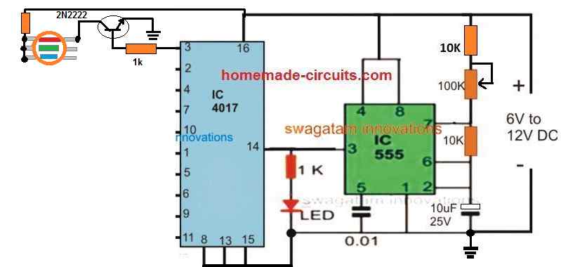
you can try the following circuit for your RGB LEDs
Repeat the transistor stage for the other two pins of the shown LED, with pin2 and 4 of the IC.
Again repeat the same with the next LED for the pin7,10,1 of the IC and so on.
The common resistor on the other side of the LED will depend on the current rating of the LED
Thank you. A great help.
Many years ago, I got a circuit of one running light with IC 74138. I still have the IC now, but lost the circuit diagram and sold the assembled one. It was a 4 channels running light. While running, except one pin all others were high and low one by one. There was another IC, I do not remember what, besides 555. The effect was beautiful. I hope you will be able to design a circuit. Please try for this Chrostmas. Thanking you.
Thank you, the proposed circuit will behave in the exact same manner. Although it has 10 outputs, it can be converted to 3 outputs by connecting the pin15 with pin7, for 4 outputs connect pin15 with pin10 and so on…
In the “Circuit Diagram with 200 LED Chaser Circuit” If I want to go directly from the 4017 to the transistor (BC547 or 2n2222) do I need a resistor between the 4017 & the transistor? If so, what value?
resistor will be needed at the base of all the transistors.
What is the max amount of led,s that can be used on a led chaser
30 LEDs with 12V supply.
Hi Swagatam,
I just realised.
It’s not the 1st but the second, connected to mains.
For what I can see, the circuit operates in 12V (Zener 12V).
I need to put this circuit in 3V, using CMOS versions of the 4017 and 555, which I own.
What would be the value of the resistors, and in order to get maximum brightness which transistores should I use in the LED’s.
Best Regards.
Nélio
Hi Nelio, for 3V operation you can change the 12V zener with 3V zener, and reduce the 1k resistor to 10 ohms, and the 0.47uF could be reduced to 0.33uF/400V
Hi,
Thanks.
Best Regards.
Nélio
Just now realized that the 1N4148 will drop 0.6V from 3V so the LEDs will be dim…In that case you can either replace them with schottky diodes or use 4V as the input
Hi,
I have redraw the circuit and at each LED cathode I have connected the Collector of a NPN transistor and the Emitter of all 6 transistors to the 10 Ohm resistor. The Base of the each transistor is connected to positive of power supply. Only thing left to do, is figure out which transistor to use and if I need or not to put a resistor at the base of each transistor.
Best Regars.
Nélio
Hi, I am afraid transistors won’t work, they have to be diodes only!
Hi,
It’s not a problem since the circuit will be powered by battery instead of mains, and I might include some transistors to trigger the LEDs, connected at the outputs of the 4017.
Best Regards.
Nélio
Good afternoon,
First i have to say: by your work, you encouraged me to start using 4017 chips.
When i noticed the array of possibilities that it gives i have made almost all the proposed variations of the chasers i’ve found in your publications, learned how to cascade them
learned using logic gates and so on. Simply put: you have inspired me to make another step forward on my self taught journey around the magic world of electronics????…
I am a keen e- bike user- and that became my only transportatinon of choice- threw my stinking car away, ..i’m rrestling now with the idea of making led chaser circuit that is speed controlled,
that would be working like a heart of my vehicle…
when standing still or going slow- its heartbeat (chasing speed ) will be also slow,
when accelerating- led chaser speed would also proportionally increase..
Unfortunately i do not know where to start.
I am using DIY ebike kit: Bafang BBSHD to propell the bike
thought also of using ADXL 335, accelerometer sensor,
but that is for now beyond my abstract understanding.
I was wondering perhaps you could have an idea how can i create clock pulse
dependant on speed and incorporate it in to one of your chaser designs..
Once again i’ d like to thank you for your time, effort , and inspiration…
With kind regards: Zibbi
Hi, Thank you, and Glad you liked the ideas presented in the above article, however for speed detection the above designs cannot be applied, instead you may try the concept presented in the following post:
https://www.homemade-circuits.com/10-led-tachometer-circuit/
Hi, good morning,
Thank you very much for the answer, since the idea of speed dependant chaser is constantly rolling over my head, i realised- i need something to crate clock pulse, not component ,but speed dependant, and suddenly had a break through…
this part was all this time sitting in front of my eyes, waiting for me to simply discover it:
Speed sensor that originally came with the e- bike kit. That is i belive ” just” a reed switch,
with the magnet attached to the wheel.Every time it passes by the sensor, there is a signal
of around 3.25v ( three wires out: plus, minus, signal )Since the circuit consists of a six 4017’s ,i used an AND gates to cascade it
which leaves me in the operation range of 5v that is exactly what that sensor needs to work properly…
So…with accelerating pulse out of the way ( i hope ) there comes the part how to maintain the circuit chasing while i’ m standing still, i thought i’ ll ask for assistance our old friend
NE 555, but it must only switch on while other ‘ clock ‘ is stilled due to a lack of acceleration,
and i thought again of a logic gates or may be a voltage comparator (LM393 or else…)
,…but again, i have yet no clue where to start….
If i could somehow keep NE555 multivibrator still , during the period when speed sensor is clocking – it could probably be called victory….provided- of course that the pulse frequency from the sensor would not exceed the max ratings of 4017 chips ( which i do not know yet) and choke them or worse burn them out,..
but well, the science is a cruel mistress ????…
With kind regards: Zibbi
Dear sir
i want to make 12 bulb circuit, but my bulbs are much higher amperes about 30A. so,
IRFZ-14 is suitable for it? or any other one?
what is the gate opening voltage and current of BT136 and IRFZ14?
trigger voltage for mosfet is 12V, for BT136 is 3V, current is not so important
Jayanth, IRFZ14 will not work as it is rated at 10amps only, you must search for a 40 amp mosfet….
sir this transformerless cct is it possible to construct it and without connecting load is it possible to measure voltage on that zener diode without spoiling the zener?
jack, it is possible, you can refer to this article
https://www.homemade-circuits.com/cheap-yet-useful-transformerless-power/
Sir I new and I am intreste to make circuit as per diagram 2. But sir the capacitor 1uf as shown in diagram connected near ic 555 the voltage of capacitor is not given. Please provide what is the volt of 1uf capacitor.
Rajesh, You can use any IC 555/4017 chaser circuit, connect the pin3,2,4 with the LEDs and connect pin15 with pin7
Sir if possible kindly provide three channel circuit which run sequencly not randomly.
that's great Rajesh, Congrats to you
Thx sir I have made that circuit and it works well.
Thx a lot for quick response sir
Rajesh, the 1uF capacitor could be rated at 25V.
also make sure to connect 1K resistor across each of the triac gates and the negative supply line.
Please upload 220V drawing PCB layout with PCB size.
or E-mail:ghulamjilani36@gmail.com
thanks.
I will try to update if time permits….
Dear Swagatam,
Thank you for your reply.
I have tried all your solutions but unfortunately with the same result.
I think it is weird because as you said the ICs are rated up to 15V.
Question:
Is it possible to build a small circuit without the use of a microprocessor for flickering some LEDs?
The flickering must simulate an arc welder, camp fire, candle light etc.?
Best regards,
Henrik
Dear Henrik, that's strange and not normal, because I have built many chaser circuits but never faced such an issue.
you can try the following single transistor flasher and use a smaller capacitor to make the oscillations look like sparking.
https://www.homemade-circuits.com/2011/12/how-to-make-single-transistor-led.html
you can use a while LED to make it more realistic, however the flashing might be consistent in nature and not abrupt like in actual arcing.
Dear Swagatam,
I have built the first circuit but without the high voltage part and the Zener diode.
It works fine at max. 5V
If I raise the voltage to above 5V the flashing of the LEDs becomes uncontrollable.
What do I need to change to use the circuit at 12V?
Thank you in advance,
Henrik
Hi Henrik, that shouldn't happen, because IC 555 and IC 4017 both are designed to work from 5V to 15V safely. THis can happen if the power supply has some issues, or if the power supply pot is not good.
try with a fixed 12V and see if the problem still persists.
or alternatively you can also try readjusting the IC 555 pot after increasing the voltage to the desired higher level
Pls post a circuit that can control 10-14 diwali lights with around 8-10 combination settings
Sir,can this circuit handle 10-14 diwali lights
what kind of light do you want to connect?
sir I made 2nd circuit led sequence working properly but triac doesn't switching all bulb are continuously ON. please help me to solve this problem.
sir I made 2nd circuit all 6 nos led chasing properly but triac doesn't switching output bulb continuously on condition. please help me to solve the problem.
…the bulbs cannot be continuously ON, make sure the triacs are connected correctly…A1 must go towards the bulb side…
Rahul, change all the 1K resistors with 220 ohm or 330 resistors and additionally connect 1K resistors between gate and ground of all the triacs and check the response
Thank you sir
Dear sir आपके दिये हुवे second circuit image में main power supply का जो circuit है उसके जरिये MOC3021 drive करने के लिय कितने value के resistance की जरुरत पड़ेगी
और इस supply के जरिये हम एक साथ maximum कितने MOC3021 का use कर सकते है
I am not exactly sure how many you can drive with 50mA but 5 or 6 optocouplers could be used…
Dear Rakesh, for driving the LED of the MOC you can use any resistor between 2.2K to 10K
Dear sir मैं आपसे कुछ इस तरह से Triac (BTA41) को Drive कर ने के लिए कह रहा था
मैंने आपके mail id पर दोबारा से image send किया है
क्रप्या इस image को देखे
Please Sir मुझे इसका हल बताइए
मतलब आपके कहने का अर्थ है 1N4007 के output से 0.33uf/400v को जोड़ना है और फिर 0.33uf/400v के एक छोर से 1k जोड़ना है और फिर 1k से Triac gate को जोड़ना है ok sir
Dear Rakesh, I have sent the image, i forgot to put 1K with the gate of the triac, so please put 1K in series with the gate
dear sir i have send you my circuit
on your email id
No, that's incorrect
…120V to 1N4007 (band side), then other end of 1N4007 to 1K, then 1K to SCR gate.
after this solder the 0.33uF/400V leads directly on the 1N4007 leads (1N4007 and 0.33uF are in parallel).
Dear sir 240V AC में, मैं अगर सिर्फ एक 1N4007 diode का use न्यूटल या फेस कर तो मुझे output voltage कितना मिलेगा ?
Please tell me sir
It's very simple…connect 120V input with the band side of a 1N4007 diode, connect the other side of the diode with 1K resistor, connect the other end of the 1K with the SCR gate.
after this connect a 0.33uF/400V capacitor right on the leads of the 1N4007
Dear sir please drow this circuit for me
please please sir i request you
My mail id rakeshmauryaup@gmail.com
connect a 1k resistor to triac gate and then connect a 0.33uF/400V capacitor and connect this capacitor end with the 120V input….also connect a diode 1N4007 parallel with the capacitor….cathode will be towards the 120V source.
Dear sir आपने जो output बताया है मुझे इसी voltage से BTA41 को ऑपरेट करना है कैसे करूँ कोई ऐसा हल बताइए जो circuit के लिए सेफ हो
Please sir
dear Rakesh, the output will be 120V DC average, but the peak will be around 310V DC
Dear sir how to make Triac Dimmer but operated by other circuit
Dear Rakesh.
0.8V will need to be amplified first with a 12V amplifier circuit or an optocoupler circuit….the output from this optocoupler can be used for driving the triac.
MOC3063 can be used for this.
Dear sir मेरे other circuit का कहने का मतलब है के दुसरे circuit द्वारा प्राप्त output voltage 0 से 0.8 DCV 200uA dimmer के लिए कम जादा कर सकते है जो की Triac को Triac Dimmer बनाने के लिए पर्याप्त नहीं है
तो मैं आपसे ये जानना चाहता हूँ triac को dimmer बनाने के लिए अभी कौन कौन से components की जरुरत पड़ेगी ?
Dear Rakesh, please explain more. which "other circuit"
Thank you sir for help me
sir मैं इस प्रोजेक्ट से हट कर एक सवाल पूछ रहा हूँ क्या मैं BTA41,BT139 और BT136 को Thyristor (SCR) की तरह use कर सकता हूँ
yes you can use triacs in place of SCRs in projects such as this:
https://www.homemade-circuits.com/2016/01/8-function-christmas-light-circuit.html
Rakesh,
What exactly are you planning to make?
Aap kya banana chahte ho pehle wo batao
yes it will
Thank you sir for help me
सर जी क्या मैं C 0.47uf/400V की जगह पर कोई और C use कर सकता हूँ सर जी अगर कोई और C हो तो बता दो पर circuit के लिए सुरक्षी हो 🙂
you can 105/400V cap
Sir good finally you have improved in your second picture
but sir you need improve in circuit other part
triac is fitted in the way your circuit but do not get that way for the entire supply triac and because of which fully AC supply cannot send. so will need to use transistors
now you make your circuit and used
and then some comment
You can see this circuit
The transistor stage is not required, the triacs can be driven directly from the IC, as shown in the second circuit
i am telling you after check and i can prove it
and i am telling you that please check in circuit
capacitor, diode and Zener diode put in the wrong direction in your second picture circuit
Swagatam sir
the power of your circuit is wrong, it will not work, please you see in the 2nd picture
i have corrected it, please check it now….
Hello sir
How can I connect 1W*5 LED to above circuit
Hello sir
How i connect 1 W*5 LED to this circuit
Hello Sandeep,
see the last circuit, you can replace the bulbs with the LEDs with a series resistor.
The mosfets can be replaced with a TIP 122 transistor as an alternative.
You can connect 3nos of 1 watt LEDs with a resistor on each transistor
Great article, thank you.
My question is can you reverse it, have the LEDs on all the time and the circuit shut them off in sequence.
thanks, that would be possible with a normal IC 4017/555 chaser circuit without the forward reverse facility….there you can achieve it by simply reversing the LED polarity….I am not sure how it could be done in the above circuits….may be by reversing all the diodes an LED polarity, but I am not very sure.
Sir on this circuit how much nos of 8mm or 5mm white leds can run
basit, divide the supply voltage with the LED forward voltage this will give you the number of LEDs that can be connected in series on each channel.
thanks sir
circuit sahi se kam ker rahahe.1k ke badle mene 220E resrstor triac gate se connect ki ya aur apke bataye huye,1k resistor gate aur circuit GND se connect kerne par led sequence sahi a rahahe.aur triac proper kam ker rahahe.sab chanel 100w lamp se try kiya lumin sahi a raha he.
sir mene triac pin 1-A1 aur pin 2-A2 hisab se lagaya. thanks sir guide karne ke liye.
you r great……..
Glad to know it's working, you are welcome Orrie!
sir
mene 12v 2amp adapter use kiya.led sequence sehi aarahahe.lekin triac kam nehi kerrahahe.no.1 chanel kam ker rahahe100w bulb lagane par lumin kam ho rahahe.baki ke 5 chanel off he.
connect a LED with 1k resistor from pin3 of IC555 to ground, it should flash, if it doesn't then the fault could be assumed to be in the 555 circuit, other wise the fault could be in your 4017 circuit….make sure all the LEDs at the gate of the triacs are connected correctly and illuminate for enabling the triacs to conduct.
sir,
triac ke gate aur GND par 1k connact kene par sequence sahi arahahe thanks. lekin triac 100w bulb flash nehi ker rahaye. No.1 chanel se sirf flash ho raha he, lekin lumin kam ho raha he.
me ne 1k ke jaga 220E resistance se triac ke gate connect kiye,lekin No.1 chanel chor ke baki sab off he.lumin thora sa change huya lekin baki kam nehi ker raha he.
sir triac pin-1-T1.pin-2/tab-T2
pin-3-G.circuit me to is hisab se nehi he….sir plz help me…..
remove the shown capacitive power supply and try with a 12V adapter as the power supply and check the response..
sorry sir,
apne samay nikal kar mere prashna ka jabab diya,lekin kam ke bajese me try nehi kar saka.
aj mene try kiya led negetive se 1k lagaker GND se connect kiye.lekin 12v 2amp smps se sequence tut raha he. plz sir help me.
sir
mene apka 2 no. circuit try kiya.lekin jo 12 v hai o kam nehi ker raha he.12 v adopter use kerne par sequence proper nehi a raha hey. plz help me sir…
try connecting 1k resistors across gate and ground of all the triacs.
how many 5w 230v bulbs can be put in single triac in parrel? is there any triac for large watt handling?
100nos if the triac (BT136 etc) is mounted on a heatsink, for more bulbs you can try other higher rated triacs.
I've made the 12V car version. I've only left out the leds before the mosfets. But it's not working. When I don't connect the positive wire going to the 22k resistor, port 8 and 4 of ic555 and to port 16 of ic4017. All the light are burning, but when i connect this positive wire nothing is working at all. Have you any idea what could be wrong and how i can check it?
that's weird, because without the positive supply connected the LEDs would never light up.
I think there's something terribly wrong with your connections or the components.
Separate the 555 and the 4017 stages….build and test them separately, once the results are confirmed you can try integrating them as per the diagram.
request indicate c code for 12 led chaser for suitable pic with fading effect.comet tail
sorry i don't have it presently with me.
you will have to connect the triac MT1 and MT2 pins with AC mains supply and the bulbs as indicated in diagram.
a cell phone charger output will also work for verifying the sequencing.
check the 4017 circuit with a 12V DC adapter and see if the sequencing is working or not.