In this post I will explain you how to build an 18 LED chaser circuit through a simple cascading of two 4017 ICs, and some passive electronic components.
Working Explanation
Here we are discussing how to make a simple LED running light which can be built by any newcomer in the field albeit the individual has some knowledge of soldering and regarding the commonly used electronic components.
The concept of a light chaser discussed here utilizes the popular Johnson’s decade counter IC 4017 for getting the desired light chasing effect. IC 555 is used as the Oscillator
The IC 555 provides the clock signals to the counter ICs. We all have probably seen how the IC 4017 can be configured for creating the light chasing effect using LEDs, however the number of maximum LEDs supported by this IC is not more than ten.
In the following paragraphs we’ll learn how to make an eighteen LED light chaser by cascading two of these ICs.
Cascading two IC 4017 Johnsons Counter for the 18 LED Effect
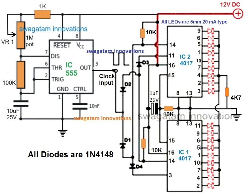
Looking at the above light chaser circuit diagram we see how the two ICs are configured so that the “chasing” or "running"of the LEDs at its outputs are carried on for 18 LEDs.
The diodes included in the circuit especially are responsible for switching the ICs into a cascading action.
The diodes make sure the IC outputs are carried forward from one IC to another, so that the “chasing” effect is pulled for the entire 18 LEDs in the array.
The whole circuit can be built over a general purpose PCB, and connected together by soldering with the help of the shown diagram.
The circuit can be operated in between 6 volts to 12 volts.
HAVE FURTHER DOUBTS? PLEASE FEEL FREE TO COMMENT!
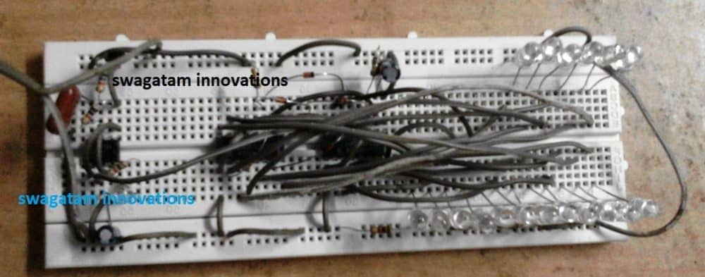
The above 18 LED cascaded chaser circuit can be also conveniently built using a 555 astable circuit, as shown below:
How to Build this
First gather your components including two 4017 decade counter ICs, one 555 IC, a 100k potentiometer, a 1k resistor, a 10nF capacitor, a 4.7 microfarad capacitor, eighteen LEDs with current limiting resistors, and a 9v to 12v DC power supply.
| Part Name / Value | Quantity | Description |
| NE555 Timer IC | 1 | Astable clock pulse generator |
| CD4017 Decade Counter IC | 2 | Cascaded sequential counters |
| 100k Potentiometer | 1 | Speed control variable resistor |
| 1k Resistor | 1 | Timing network resistor |
| 10nF Capacitor | 1 | Control voltage decoupling capacitor |
| 4.7µF Electrolytic Capacitor | 1 | Timing capacitor |
| LEDs | 18 | Extended output display indicators |
| Resistors (330Ω / 470Ω) | 18 | LED current limiting resistors |
| 9V to 12V DC Power Supply | 1 | Power source |
Now place the 555 timer on the breadboard, connect pins 8 and 4 to the positive rail, connect pin 1 to the negative ground rail, and wire its astable clock setup using the 1k resistor on pin 7, the 100k pot between pins 7 and 6 and a bridge between pins 6 and 2 with the timing capacitor connected to ground.
Position the first 4017 IC, connect its pin 16 to the positive rail, tie pins 8, 13, and 15 to ground and route the clock signal from pin 3 of the 555 timer into pin 14 of this counter.
After that place the second CD4017 IC alongside the first, connect its pin 16 to the positive rail, tie pins 8, 13, and 15 to ground, and link its clock input at pin 14 to the carry out pin 12 of the first counter to cascade the sequence.
In the end connect the eighteen LEDs with their appropriate resistors across the sequential output pins of both CD4017 ICs, ranging from the outputs of the first counter through the outputs of the second counter to ground and apply power to run the extended light sequence.
Video Clip of the above circuit in operational mode:



Need Help? Please Leave a Comment! We value your input—Kindly keep it relevant to the above topic!