• Skip to main content
  • Skip to primary sidebar

Homemade Circuit Projects

Need circuit help? Post them in the comments! I've answered over 50,000!

Blog | Categories | About | Hire Me | Contact | Calculators-online
You are here: Home / Lamps and Lights / LED Chaser Circuit with Slow Adjustable Fading Effect

LED Chaser Circuit with Slow Adjustable Fading Effect

Last Updated on October 17, 2026 by Swagatam Leave a Comment

The next circuit below discusses a cool chasing LED light circuit that features a timed delay fading slow transition effect across the whole illuminated sequencing LEDs. The idea was requested by Mr. Tamam.

Table of Contents
  • Technical Specifications
    • Circuit Diagram
  • Circuit Working
    • For Improved Fading effect
    • Parts List

Technical Specifications

I want to design a circuit consisting equal no. of Red, Green, Blue, Yellow, Violet, Orange and White LEDs. I want to have these LEDs in a continuous and smooth transition effect like
below,

At first, Red branch of LEDs lit for a preset time then slowly fade out and then Green branch of LEDs fade in and fade out then next branch fade in and so on.

I would like to have control on transition time delay, light timing, fade in or out timing if possible. And I don't want to use any Programmable IC for this. So please please let me know if it possible without any programmable IC. It is okay even if I need several ICs to accomplish the job. You just show me the way !!

Thank you very much once again for your valuable time and for a quick reply! I am looking forward to you response!!

Circuit Diagram
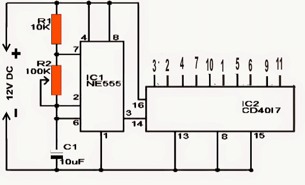
LED chaser circuit diagram with slow fade effect
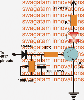
BJT driver circuit diagram for LED chaser output

Circuit Working

The proposed chasing, fading LEd light circuit may be understood with the help of the above schematic and the following description:

The upper circuit is a standard LED chaser design comprising of a decade counter IC 4017 and a clock oscillator using IC 555 astable configuration.

This IC 4017 generates a sequencing high logic (equal to supply voltage)  across its entire output pins in response to the clocks at its pin14 from the IC 555.

If we connect LED directly across the 4017 outputs and ground, the LEDs would illuminate in a dot mode fashion from the first pinout upto the last in a sequencing pattern resembling a chasing effect.

This effect is pretty ordinary and we all probably have come across and built such light chasers circuits quite often.

However as per the request the effect needs to be enhanced by adding a slow transition over the LED illumination as it sequences across the entire channel.

This fading transition on the sequencing LEds is expected to generate an interesting group LED chasing effect instead of an illuminated dot like appearance.

The above intriguing show could be easily implemented by connecting the LEDs to an intermediate BJT delay generator circuit.

This BJT circuit becomes responsible of generating the intended transition delay over the LED illumination and can be witnessed in the lower design.

This stage needs to be repeated across all the selected outputs of the 4017 outputs for achieving the desired chasing, fading slow transition over the LEDs.

As requested the rate of the above fading slow transition could be controlled by adjusting the given pot.

The circuit is basically a simple delay timer which sustains the illumination on the sequencing LEDs for a few moments depending upon the set value of the pot.

The stored charge on the capacitor produces this timed delay effect on the LEDs which could be predetermined as per ones own choice.

The speed of the sequencing could be also altered by tweaking the 555 IC 100k pot as per individual choice which this could in turn interfere with the delay transition effect and thus is a matter of some trial and error until the most attractive set up is determined.

For Improved Fading effect

For an improved fading response the LED could be connected across the emitter and ground of the circuit, as indicated the below given diagram:
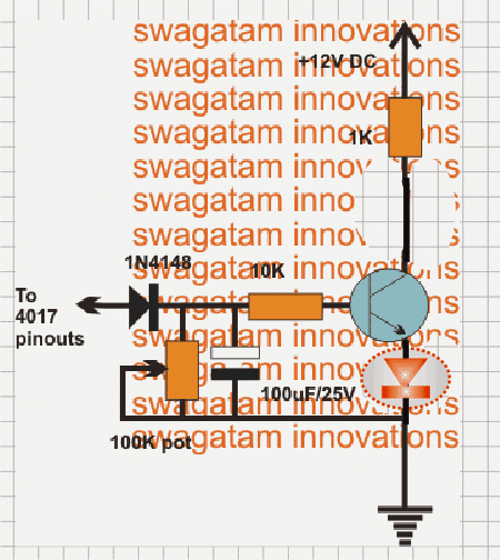
BJT LED driver circuit diagram with slow fade

Parts List

Here is the combined parts list for the circuits presented in the article:

ComponentDescription / ValueQuantity
IC1NE555 Timer IC1
IC2CD4017 Decade Counter IC1
Q1 to QnBC547 (or equivalent NPN Transistor for driver stages)Per output channel
R1, R2Resistors (per timing network specification)As per design
VR1100k Potentiometer (Speed Control)1
VR2 / R_fadeVariable or fixed resistors for fading delayAs per channels
C1Timing Capacitor (Electrolytic)1
C2Ceramic Disc Capacitor (0.01µF typically for 555 pin 5)1
C_fadeCapacitors for the BJT delay/fading networkPer output channel
LEDsStandard LEDs (grouped by color/branches)Multiple (as required)
Resistors (LED)Current-limiting resistors for LEDsPer LED branch

You'll also like:

  • LED structuresLight Emitting Diodes (LED) Explained
  • 10 Automatic Emergency Light Circuit Diagrams Explain
  • smd led5630 SMD LED Driver/Tube light Circuit
  • Arduino Random RGB Light Generator Circuit

Filed Under: Lamps and Lights Tagged With: Adjustable, Chaser, Effect, Fading, LED, Slow

About Swagatam

I am an electronics engineer and doing practical hands-on work from more than 15 years now. Building real circuits, testing them and also making PCB layouts by myself. I really love doing all these things like inventing something new, designing electronics and also helping other people like hobby guys who want to make their own cool circuits at home.

And that is the main reason why I started this website homemade-circuits.com, to share different types of circuit ideas..

If you are having any kind of doubt or question related to circuits then just write down your question in the comment box below, I am like always checking, so I guarantee I will reply you for sure!

Previous Post: « Make this Knight Rider type LED Chaser Effect
Next Post: LED Chaser Circuits using IC 74C164 and 74LS164 »

Reader Interactions

Need Help? Please Leave a Comment! We value your input—Kindly keep it relevant to the above topic! Cancel reply

Your email address will not be published. Required fields are marked *

Primary Sidebar

My YouTube Channel

Circuit Simulator: Draw and Simulate Schematics

circuit simulator image

Categories

  • Arduino Projects (95)
  • Audio and Amplifier Projects (134)
  • Automation Projects (18)
  • Automobile Electronics (104)
  • Battery Charger Circuits (90)
  • Datasheets and Components (109)
  • Electronics Theory (151)
  • Energy from Magnets and Earth (43)
  • Games and Sports Projects (11)
  • Grid and 3-Phase (20)
  • Health related Projects (27)
  • Home Electrical Circuits (13)
  • Indicator Circuits (16)
  • Inverter Circuits (99)
  • Lamps and Lights (170)
  • Meters and Testers (72)
  • Mini Projects (28)
  • Motor Controller (68)
  • Oscillator Circuits (30)
  • Pets and Pests (15)
  • Power Supply Circuits (91)
  • Remote Control Circuits (50)
  • Security and Alarm (65)
  • Sensors and Detectors (107)
  • SMPS and Converters (46)
  • Solar Controller Circuits (62)
  • Temperature Controllers (44)
  • Timer and Delay Relay (51)
  • Voltage Control and Protection (44)
  • Water Controller (37)
  • Wireless Circuits (31)

Subscribe to get New Circuits in your Email

Other Links

  • Privacy Policy
  • Cookie Policy
  • Disclaimer
  • Copyright
  • Videos
  • Sitemap

People also Search

555 Circuits | 741 Circuits | LM324 Circuits | LM338 Circuits | 4017 Circuits | Ultrasonic Projects | SMPS Projects | Christmas Projects | MOSFETs | Radio Circuits | Laser Circuits | PIR Projects |

Recent Comments

  • Swagatam on Understanding Crystal Oscillator Circuits
  • Swagatam on Simple SG3525 Sine Wave Inverter Circuit Explained
  • Swagatam on Arduino SPWM Generator Circuit – Code Details and Diagram
  • सुधीर चौहान on Understanding Crystal Oscillator Circuits
  • Asif marth on Arduino SPWM Generator Circuit – Code Details and Diagram

Social Profiles

  • Twitter
  • YouTube
  • Instagram
  • Pinterest
  • My Facebook-Page
  • Stack Exchange
  • Linkedin

Calculators

  • ZVS Induction Heater + Tank Calculator Tool
  • Zener Diode Calculator
  • Wire Current and Thickness Calculator (Ampacity Calculator)
  • Voltage Divider Calculator
  • Transistor Base Resistor Calculator
  • Transistor Astable Multivibrator Calculator
  • TL431 Calculator
  • Solar Panel, Inverter, Battery Calculator
  • Ferrite Core Air Gap Calculator Tool
  • Parallel MOSFET Calculator Tool: How to Connect MOSFETs in Parallel Safely
  • LC Resonance Calculator for EV Battery Charger Circuits
  • LED String Series Resistor Calculator
  • PFC (Power Factor Correction) Calculator Tool: 3kW
  • Passive Power Factor Correction (PFC) Calculator
  • LM567 IC Calculator Tool
  • SMPS Flyback Boost Converter Calculator
  • Shunt Resistor Calculator for Ammeters
  • SCR and Triac Gate Resistor Calculator
  • Battery Back up Time Calculator
  • Boost Converter Calculator (Non-Isolated)
  • Bootstrap Capacitor Calculator
  • Buck Converter Calculator
  • Buck-Boost Converter Calculator
  • Capacitance Reactance Calculator
  • DCM Flyback Transformer & Wire Gauge Wire Size Calculator Tool
  • Filter Capacitor Calculator
  • IC 4047 Calculator (Frequency and PWM)
  • IC 4060 Calculator
  • IC 555 Astable Calculator
  • IC 555 Monostable Calculator
  • IC SG3525, SG3524 Calculator
  • Inductance Calculator
  • Induction Heater Inductor and Resonant Frequency Calculator
  • Induction Heater Work Coil Calculator
  • Inverter LC Filter Calculator
  • LC Resonance Calculator
  • LED Current Calculator
  • LM317, LM338, LM396 Calculator
  • NAND/NOT Gate RC Values Calculator
  • NOT, NAND Gate Frequency Calculator
  • Notch Filter Calculator Tool
  • Ohm’s Law Calculator
  • Phase Angle Phase Shift Calculator
  • Power Factor (PF) Calculator
  • RC Filter Calculator
  • Reactance Calculator
  • Sine Table Calculator for SPWM Arduino Code
  • Small Signal Transistor(BJT) and Diode Quick Datasheet
  • SMPS Calculator for Toroidal Ferrite Transformers
  • SMPS Flyback Transformer Calculator – Design by Target Duty Cycle
  • TL431 Calculator
  • Op-Amp Hysteresis Resistor Calculator

© 2026 · Swagatam Innovations