In this article I have explained two very useful school bell timer circuits which can be used for ringing school bell automatically for each period as per the set time duration.
The first circuit is designed using a handful of IC 4060, and the second circuit concept is configured around the IC 4017. I have explained the concepts with more details.
In the first concept below I have explained how to make a very simple 10 stage long duration programmable timer circuit which can be used as a school bell timer circuit.
All the 10 stages can be individually programmed from zero to 5 hours. The circuit can be modified in many different ways to suit other specific related applications.
The Circuit Concept
Normally in most of the schools even today the period bells are rung manually by the concerned staff or the peon.
Although the job is quite traditional and is carried out without much difficulty and reasonably accurately, the concerned person has to be always on a stand by position for implementing the actions.
However with the help of a simple electronic circuit the above implementations could be made fully automatic, eliminating human intervention, thus saving a lot of inconvenience and time.
The functioning of the proposed automatic school bell period timer circuit may be understood with the following points:
Circuit Operation (Practically Tested OK and Working)
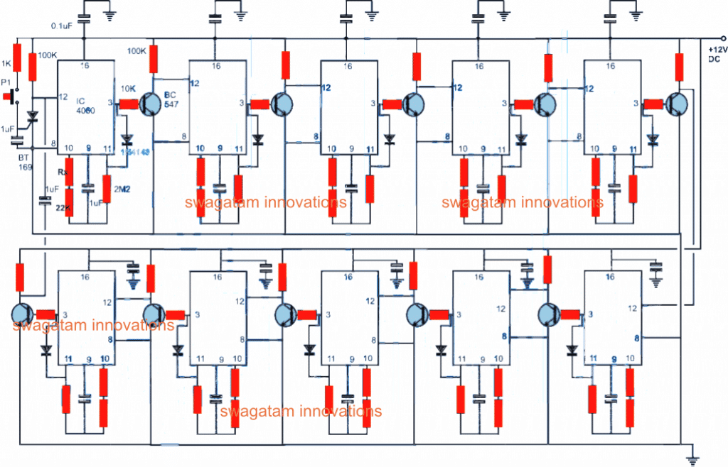
At the first glance the circuit might look quite complex, but seeing it closely shows that actually it's very simple, just a repetition of identical stages for the required number of times.
We'll try to understand the top left stage and that will clarify the entire circuit within no time.
The circuit is based on the timer/oscillator chip 4060. It's wired in its usual timer/counter mode with the help of the resistors and capacitors fixed over its pin#9, 10,11.
Rx determines the time period for which the IC counts until its pin#3 becomes high.
The value of this resistor may be determined through trial and error for acquiring the required time intervals for all the relevant subsequent stages.
The design is repeated for all the stages.
However the top left stage being the first power switch ON stage is rigged with additional components.
When the push button P is pressed, the SCR latches, grounding pin#12 of the IC.
This initiates the counting procedure within the IC.
After the predetermined time lapses, pin#3 of the IC goes high and also the stage gets latched via the diode connected to pin#11.
With pin#3 high, the associated transistor pulls pin12 of the next stage to ground, which in turn initiates the counting of the second stage.
The procedure is repeated exactly the same way for the second stage also, and consequently all the corresponding stages get activated serially one after the other as per the set time for the individual stages.
When the the time period for the last stage is elapsed (bottom left), the transistor at pin#3 momentarily grounds the anode of the SCR via the 1uF capacitor switching off the SCR and the entire circuit.
The situation resets the whole circuit to its original state, until the push button is pressed the next morning for initiating yet another cycle.
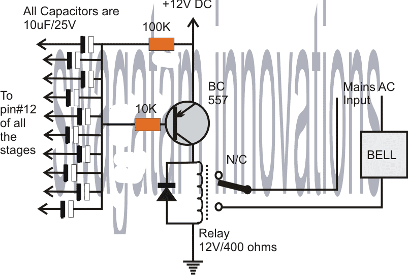
The second circuit shows the driver stage which is responsible for ringing the AC bell in response to the triggering of each subsequent stages in the given order.
The diode ends are connected to pin#12 of the different stages.
The moment these pins are pulled to ground by the BC547 transistors, sends a momentary biasing to the BC557 transistor which in turn activates the connected relay and the load for a brief period of time depending upon the values of the transistor base resistor and the capacitor (chosen arbitrarily here)
Automatic School Bell System Using IC 4017 and IC 555
The second concept below explains how to construct an automatic school bell system using the IC 4017 which can be programmed to activate an AC bell in regular intervals (between 0 minute and 99 minute) which can be set using DIP switches and the duration of the bell ring can be adjusted from 0 to 11 seconds using the provided potentiometer.
You can also add an optional 7 segment display stage to showcase minutes.
The circuit is constructed using commonly available components such as IC 555, IC 4017, IC 4026, IC 7408 and other miscellaneous active and passive components. Let’s start with the block diagram.
- You may also want to read about:
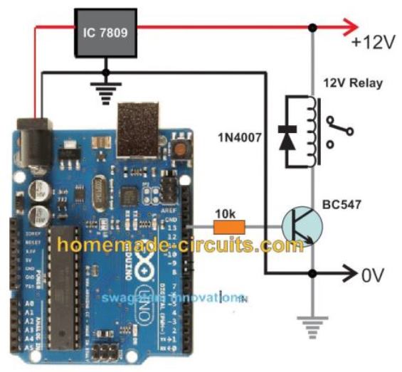
- Arduino Based School bell system
Block Diagram:
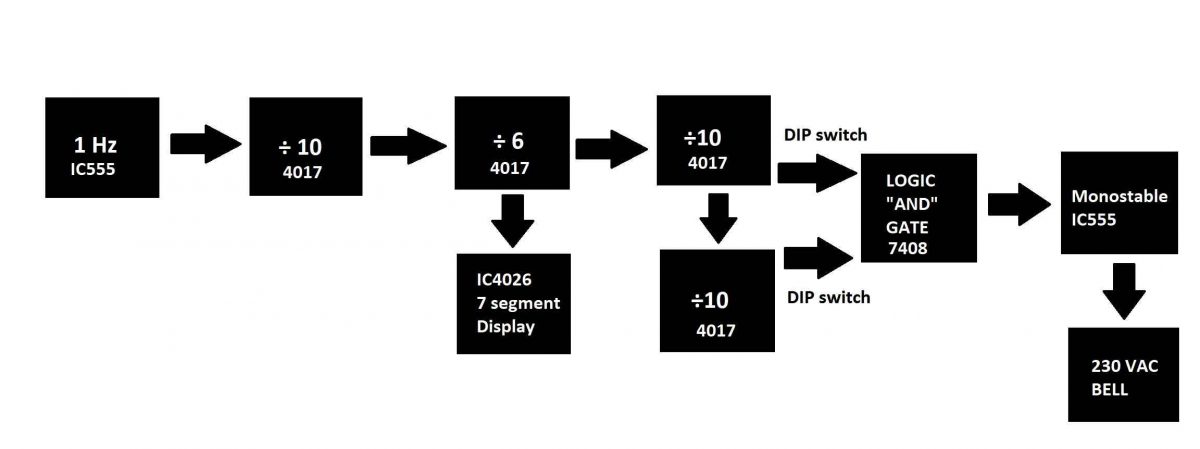
The block diagram of the school timer using IC 4017 starts from left hand side and ends at right hand side.
- The first stage of the block diagram is a 1 Hz generator using IC 555 which provides the clock signal for rest of the circuit.
- There are three IC 4017 configured as “divided by 10” and one IC 4017 configured as “divided by 6”. The first IC 4017 divides the input clock by 10 and outputs one clock cycle for every 10 clock cycle (seconds).
- Another IC 4017 is cascaded with the previous IC 4017, which divides the input clock signal by a factor of 6. Now we will get one clock cycle for every minute.
- Now an optional stage can be introduced here to count the minutes which have explained in the later part of this post.
- The last two IC 4017s are configured as divided by 10 and one of the IC will output the “units digit” of the minute and the other IC will output “tens digit” of the minute.
- The time can be set using the provided two DIP switches for units and tens position of minute digit.
- A logic AND gate is utilized to make decision, when the two inputs from IC 4017s are high the Logic gate output turns high and triggers the monostable multivibrator.
- The monostable multivibrator’s output turns high for pre-defined period of time which in turns activates the bell until the multivibrator turns low.
Now let’s dive into the circuit diagram of each stage.
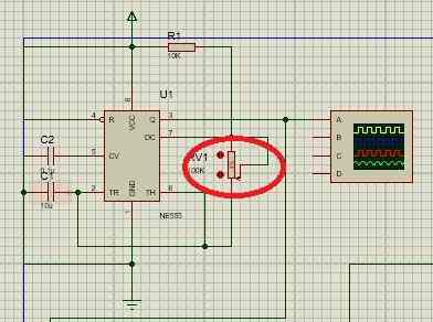
1 Hz generator using IC 555 (Astable Multivibrator):
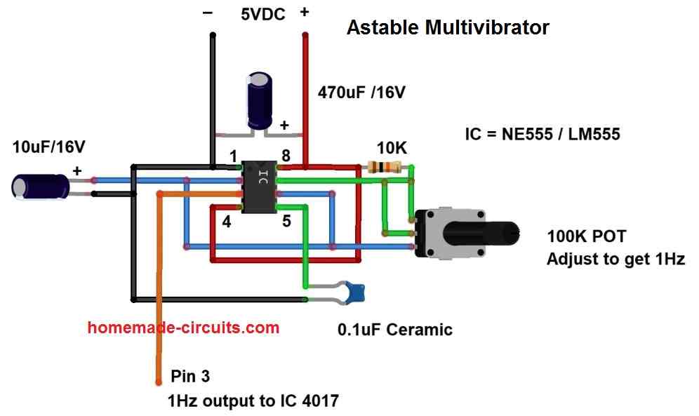
The above circuit consists of an IC 555 configured as astable multivibrator which generates square wave at pin number three.
It can generate 1 Hz clock signal if you adjust the 100K potentiometer correctly.
The timing accuracy of rest of the circuit depends on how accurately you calibrate this stage.
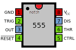
IC 555 pin diagram:
Timer / Counter stage:
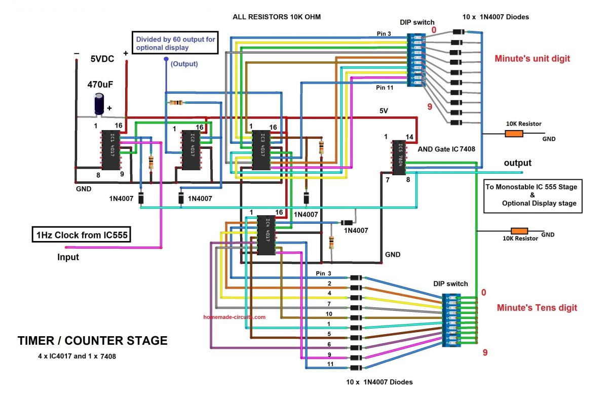
The above circuit is responsible for counting / tracking the time according to astable IC 555’s clock input; the maximum time this circuit can track is 99 minutes.
The above circuit receives 1 Hz clock via pin number 14 (clock input) of IC1 4017 which divides the clock by a factor of 10. The divided clock cycle is outputted at carry-out pin, which is pin number 12.
The IC2 4017 is cascaded with IC1 and it receives the clock pulse from pin 12 of IC1.
The IC2 is configured to divide the input clock by a factor of 6; this is achieved by connecting the reset pin number 15 to 6th sequential output of IC2 which is pin number 5.
Now at pin number 5 we will get 1 pulse for every minute.
The output of IC2 (one pulse per minute) is connect to IC3 which divides the output by a factor of 10 which gives us unit digit of a minute.
The IC3’s carry-out signal is fed to pin number 14 of IC4 4017 which gives us tens digit of the minute.
The output of IC3 and IC4 is fed to logic AND gate IC 7408 via two DIP switches which is used for setting the time for activating the bell. When the logic gate’s inputs receive as high the output turns high which triggers the next stage.
There are 10 diodes at each DIP switches to prevent short circuit between output pins of IC 4017s which could occur when you accidently turn ON two or more dip switches simultaneously.
The output of AND gate is not only fed to the next stage but also fed to reset pins of all IC 4017s via diodes, so that when the desired time is reached, all the IC 4017’s count resets to zero.
NOTE: Both the DIP switches scales from 0 to 9, one for unit digit and one for tens digit. Example: Say you want to activate the bell for every 45 minute, slid the 5th DIP switch ON for units digit and 4th DIP switch ON for tens digit.
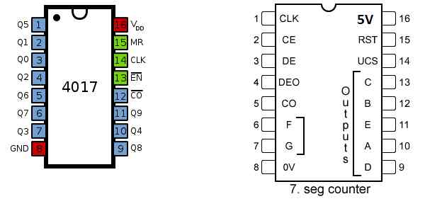
Pin diagram of IC 4017 and IC 4026:
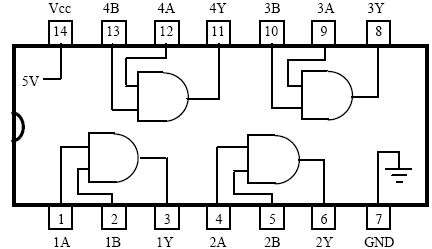
Pin diagram of IC 7408:
Monostable multivibrator stage:
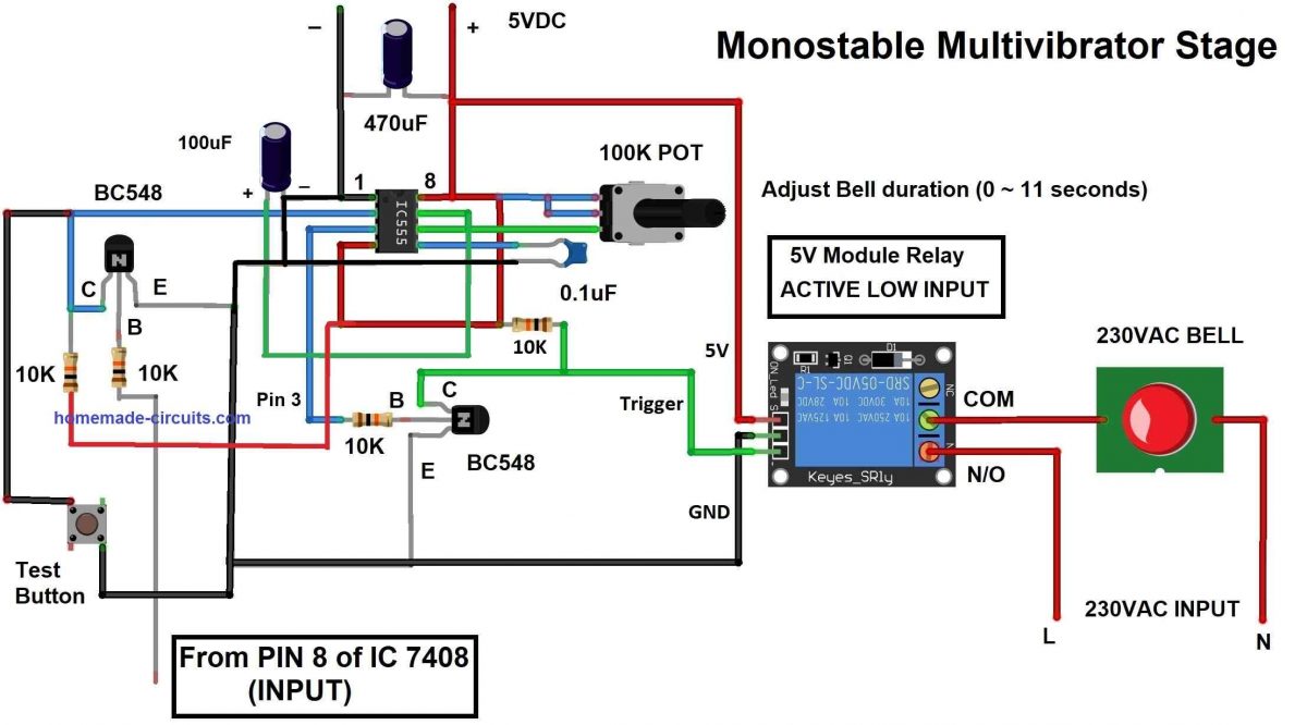
The above circuit consists of an IC 555 which is configured as monostable multivibrator.
This stage is responsible for activating the bell for a predetermined period of time in seconds by adjusting the provided 100K potentiometer.
You can set the time from 0 to 11 seconds maximum after which the bell deactivates.
The circuit receives its trigger signal from AND gate’s output. The signal is received by an NPN transistor at left most side (of the diagram) inverts the signal to negative pulse which is necessary to trigger the IC 555.
A test button is provided to test the duration of the bell ring while adjusting the potentiometer and also for regular maintenance / debugging the circuit.
A 5V relay module is employed to trigger the 230 VAC bell. The relay must be a low level trigger type to work with the circuit.
A transistor is connect at pin 3 of IC 555 to trigger the relay and the transistor is here to invert the IC 555’s output signal from positive pulse to negative pulse.
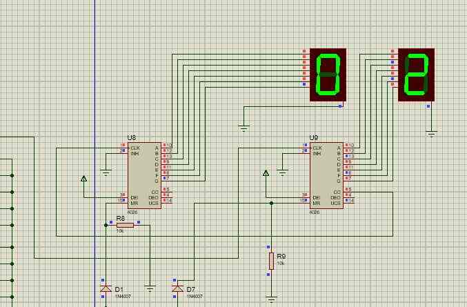
7 segment minute counter (optional stage):
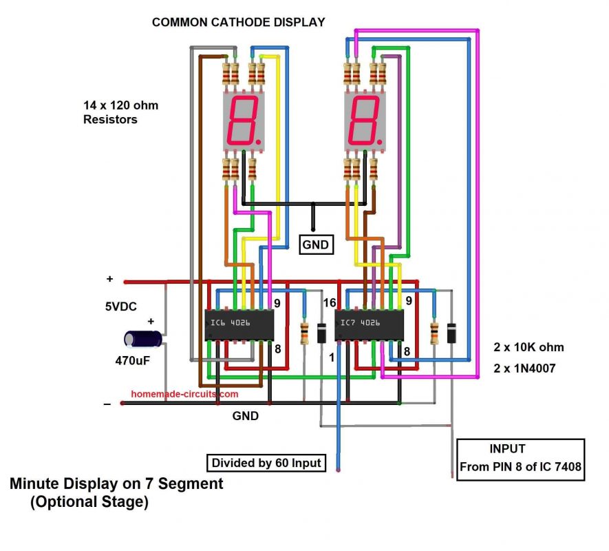
The above circuit stage is optional for displaying minutes by tracking the clock cycle from IC2 4017 which outputs 1 clock cycle per minute.
When the bell gets activated the display resets to zero and counts the time again.
The circuit consists of just two IC 4026s which are used for driving common cathode 7 segment displays.
The two ICs are cascaded to count from 00 to 99 and the clock input is fed through pin 1 of IC7 and the carry-out is at pin 5, which is fed to IC6’s clock input pin 1.
Resetting the digits to 00 is achieved by feeding AND gate’s output to pin 15 of both the IC 4026 through a diode.
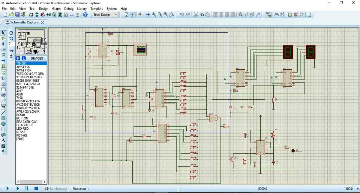
Simulation Result for the 4017 School Bell Timer:
We have developed a simulation on proteus software of the proposed project so that you test the circuit on your computer.
IC 555 clock generator:
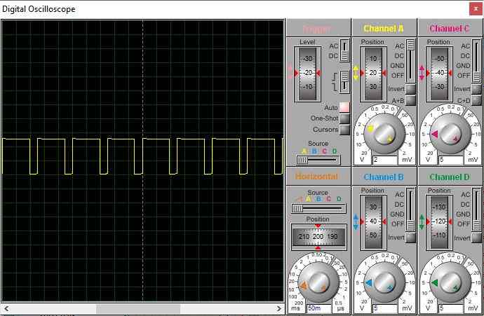
In the simulation you may set the IC 555’s output to more than 1 Hz to see the intended result faster by adjusting the pot to minimum position as illustrated below.
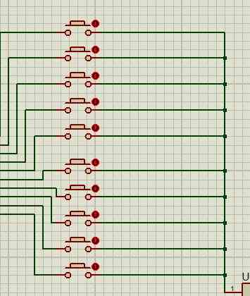
DIP switch:
In this simulation we have used push buttons in the place of DIP switch and does the same job of a DIP switch when you lock the button using the red dot beside every push button. Press the red dot in units digit and tens digit to set a time.
You can see minutes on the 7 segment display as illustrated below:
Download the Simulation files from the below given link:


Questions & Answers
Buenas noches Ing. Swagatam he leído sus dos proyectos y he quedado fascinado con ellos y sus explicaciones, aparte de el simulador, personajes profesionales y maestros como Ud. son los que dan a estos espacios interés por la electrónica, debiese tener un canal por youtube para hacerlos más amenos, felicitaciones y exitos-
Thank you so much Luis, for your kind words. I appreciate it very much.
Yes, I do have a Youtube channel, you can find it here:
https://www.youtube.com/channel/UCBsXnCs5D2Tx-wipYZ1L7PA
actually i cannot access this project from given the link.Please help me. Can you share the project?(For 2 simple school bell timer circuit project)
Sorry, for the wrong link, here’s the correct one:
https://www.youtube.com/channel/UCBsXnCs5D2Tx-wipYZ1L7PA
Thank you very much sir, you are the best
You are welcome!
Hello Mr. Swagatam. My name is Carlos and I am a faithful follower of the website. I want to ask you for a timer circuit. The characteristics are, 1 or maybe 1 1/2 hours on. And 2 or 3 hours off. But it also only has to work during the day. Thank you.
Thanks Carlos for being a dedicated follower of this blog, appreciate it. For getting a dual, adjustable timer circuit, you can try the following concept:
To make it work during day, you can add a 3M3 resistor between pin#12 and positive line for the upper 4060 IC, and replace the existing 1M resistor at pin#12 with a 10K resistor and add an LDR in series with it.
Simple Programmable Timer Circuit
Hello sir,
i have difficulties in setting up my RTC code.
please can i get any code?
Hello Jay,
You can check out the following article:
https://www.homemade-circuits.com/automatic-school-college-bell-system-using-arduino/
I confirmed the codes, they are compiling correctly.
Hey! We have a project on our school which is The School Bell with timer and using parallel port. Can you help us with what to buy and the circuit diagram. PLS HELP US ITS WHAT WE NEED FOR THE FINALS 🙁 PLEASE HELP! THANKS. email me at russjacobs21@gmail.com
Hi, if you are interested to build the above design, you can go ahead and try it out, build it as exactly shown.
plz send mi all details of this project buz m i also doing same project mail id-kiranhande04@gmail.com
Hello Swagatam
This very complicated circuit could be replaced by just one 8-pin PIC12f675 with the appropriate software
Hello xavier, may be you did not go through the circuit carefully, the entire circuit is just a repetition of a single IC stage, so that makes it extremely easy to understand and make…the only disadvantage being the size which could a little bulky.
It can be built by any new hobbyist and customized as per preference to any degree anytime, it does not require any hardware or coding…and the results could be assumed on par with any sophisticated design.
can please upload a mini project based on process control timer
please elaborate