 Homemade Circuit Projects

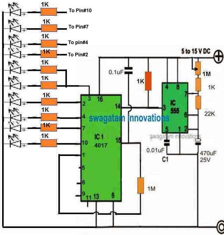
If you wish to make a sequencing LED pattern which will imitate LED chasing from center to outward, then you can try the following design, which is our 9th design.
Here, group of 5 LEDs will appear running from pin#3 towards pin#10, giving an impression that the LEDs are chasing from center pin#3 to pin#10, outwards on either directions.
You can replicate the effect using all the 10 outputs of the IC 4017.
What is an Outward Chasing LED Circuit
A normal LED chaser moves light in one direction like from left to right. But an outward chaser starts the light from the center and pushes it outwards towards both edges at the same time. It looks like the light is splitting or expanding from the middle. You can make this with a basic 555 timer IC and a CD4017 counter IC.
How the Circuit Works
The circuit has two main parts. The first part is the 555 timer which is connected as an astable multivibrator. This means that it just produces continuous clock pulses or square waves. The output of pin 3 of the 555 goes straight to pin 14 of the CD4017 which is the clock input. You can adjust the speed of the chasing effect by turning right or left a 100k pot connected to the 555 timer.
The second part is the CD4017 counter IC. Every time a clock pulse comes from the 555 timer, the CD4017 turns on its output pins one after another, starting from pin 3 up to pin 11.
Wiring the LEDs for Outward Effect
To get the outward effect you do not wire the LEDs straight in a line with the IC output pins. Instead you place the LEDs physically in a row and pair them up.
For example if you have 10 LEDs placed in a row from left to right, LED 5 and LED 6 are in the exact center. You connect both of their anodes to the first output pin of CD4017 which is pin 3.
Then you take LED 4 and LED 7 which are next to the center, and connect them to the second output pin which is pin 2. Then LED 3 and LED 8 connect to pin 4. Then LED 2 and LED 9 connect to pin 7.
Finally LED 1 and LED 10 at the far edges connect to pin 1.
When the CD4017 starts counting, then center pair turns on first, then turns off while the next outer pair turns on, and so on until it reaches the edges. Then the cycle repeats instantly.
Part List
| Component | Quantity | Value |
| IC 555 | 1 | timer ic |
| IC CD4017 | 1 | decade counter ic |
| LEDs | 10 | any standard color |
| Potentiometer | 1 | 100k ohm |
| Resistor | 1 | 10k ohm |
| Resistors | 5 | 470 ohm or 1k ohm |
| Capacitor | 1 | 10uF electrolytic |
| Capacitor | 1 | 0.01uF ceramic |
| Power Supply | 1 | 9V to 12V DC |



Need Help? Please Leave a Comment! We value your input—Kindly keep it relevant to the above topic!