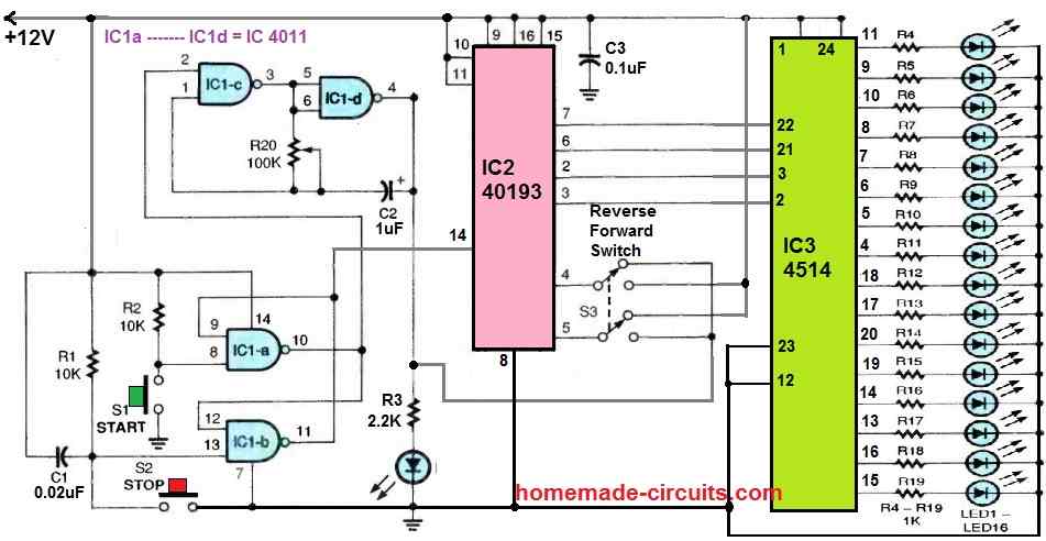
In the following LED chaser circuit concept, I will explain how the circuit sequentially turns on and off 16 LEDs using a 24 pin decoder IC 4514.
A four-bit binary input is used by the CMOS 4514 binary-to-decimal decoder, IC3, to go forward and activate each of the 16 outputs.
How the Circuit Works
The binary input data for the 4514 decoder IC3 is provided by IC2 40193, which is a binary up/down (reverse/forward) counter.
Two gates of a 4011 quad 2-input NAND gate, IC1c and IC1d, are coupled to form a low-frequency, astable-oscillator clock circuit. C2 and R20 control its operating frequency.
IC1-a and IC1-b, the final two gates of the 4011, are set up as a set-reset flip-flop latching circuit.
Switches S1 and S2 control the start and stop functions of the device, respectively, while S3 enables the up/down sequencing feature of IC2.
This is how the circuit operates:
The oscillator is started by making pin 2 of IC1c high when S1 is pressed. This latches the output of IC1a at pin 10 high.
At the same time, pin 14 of IC2's reset input is latched low, enabling the IC to count up or down depending on how S3 is positioned.
As the clock runs, the LEDs (LED1 ot LED16) turn on and off sequentially, one at a time.
The sequence restarts once the final LED in the series turns


Need Help? Please Leave a Comment! We value your input—Kindly keep it relevant to the above topic!