Though the more complex lighting might need the incorporation of microcontroller ICs, simpler yet very interesting light effects can be generated through ordinary ICs like IC 4017 and IC 555 as shown below.
This is our first LED chaser design which requires very few components for the configuration.
(The 100K pot can be adjusted to get any desired chasing speed or rate)
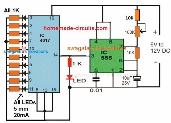
How to Make it
First you have to collect your components including a 555 IC, a 4017 decade counter IC, a 100k potentiometer, a 1k resistor, a 10nF capacitor, a 4.7 microfarad electrolytic capacitor, ten LEDs with their current limiting resistors, and a 9v to 12v DC power supply.
| Part Name / Value | Quantity | Description |
| NE555 Timer IC | 1 | Astable clock pulse generator |
| CD4017 Decade Counter IC | 1 | Sequential decade counter |
| 100k Potentiometer | 1 | Speed control variable resistor |
| 1k Resistor | 1 | Timing network resistor |
| 10nF Capacitor | 1 | Control voltage decoupling capacitor |
| 4.7µF Electrolytic Capacitor | 1 | Timing capacitor |
| LEDs | 10 | Output display indicators |
| Resistors (330Ω / 470Ω) | 10 | LED current limiting resistors |
| 9V to 12V DC Power Supply | 1 | Power source |
Next place the 555 timer IC onto your breadboard and connect pin 8 and pin 4 together to the positive supply rail while connecting pin 1 to the negative ground rail.
Then wire the timing network by connecting the 1k resistor from pin 7 to the positive rail, placing the 100k potentiometer between pin 7 and pin 6, and bridging pin 6 directly to pin 2.
Now add the capacitors by connecting the 10nF capacitor between pin 5 and ground, and the 4.7 microfarad electrolytic capacitor between pin 2 and ground with its positive leg on pin 2.
After that, place the 4017 decade counter IC onto the breadboard, connecting its pin 16 to the positive rail and its pins 8, 13, and 15 to the ground rail.
Then establish the clock link by running a wire from pin 3 of the 555 timer IC into pin 14 of the CD4017 counter IC.
Finally connect the ten individual LEDs with current limiting resistors to the ten decoded output pins of the CD4017, ranging from pin 3, 2, 4, 7, 10, 1, 5, 6, 9, to pin 11, back to the ground rail and apply power to start the running light sequence.
- For learning the pinouts and datasheet of the IC 4017 please refer to this article
- For a detailed explanation regarding IC 555 astable, you can click on this article
As can be seen in this configuration, in response to the pulses from IC 555, the IC 4017 generates a running or chasing light pattern across the connected 10 output LEDs. The chasing pattern goes on repeating itself from start to finish as long as the IC 555 keeps pulsing pin #14 of the IC 4017.

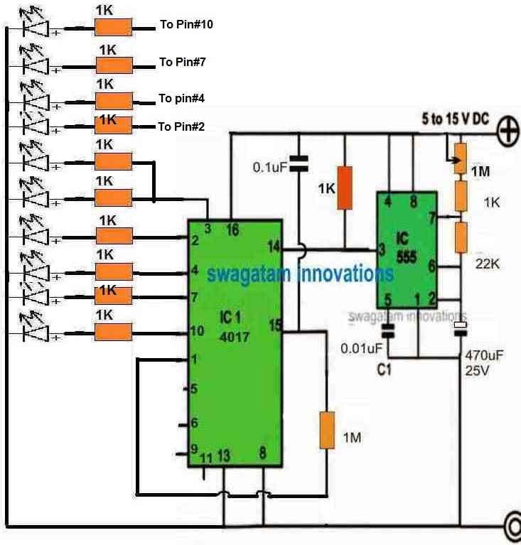

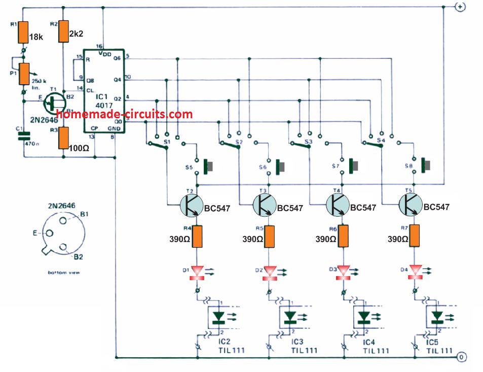

Need Help? Please Leave a Comment! We value your input—Kindly keep it relevant to the above topic!