• Skip to main content
  • Skip to primary sidebar

Homemade Circuit Projects

Need circuit help? Post them in the comments! I've answered over 50,000!

Blog | Categories | About | Hire Me | Contact | Calculators-online
You are here: Home / Lamps and Lights / 100 to 200 LED Reverse Forward Chaser Circuit for Diwali, Christmas Decorations

100 to 200 LED Reverse Forward Chaser Circuit for Diwali, Christmas Decorations

Last Updated on October 16, 2026 by Swagatam Leave a Comment

In this post I will discuss how to build a simple LED chaser circuit with a push pull or reverse forward sequencing effect. Also, in the later part of the article I have explained how this simple LED chaser could be upgraded to a 100 to 200 LED laser circuit with a reverse forward LED sequencing effect.

Table of Contents
  • Introduction
    • Understanding IC 4017 pinouts
      • Circuit Diagram
    • How it Works
      • Parts List for the proposed 4017 LED light chaser circuit
  • Adding More LEDs
    • Circuit Operation
      • Circuit Diagram with 200 LED Chaser Circuit
    • How to Connect the LEDs
    • Circuit Diagram for Series Parallel LED Connections
      • Parts List

Introduction

As learned earlier, an LED light chaser circuit typically refers to an electronic configuration able to generate or illuminate a group of LEDs in some predetermined sequence. One popular IC 4017 is very commonly employed for making this type LED sequencer circuit.

Here also the IC basically is a Johnson's 10 stage decade counter/divider and can be used for many interesting light pattern generations, and may be used for various decorative purposes.

So far we have circuits using the above IC for producing chasing light effects, however making the IC create  "reverse" "forward" "chasing" pattern with LEDs is something many of us might not be acquainted with. Here I have explained how to make a simple yet effective to and fro or reverse forward light chaser circuit using LEDs.

Understanding IC 4017 pinouts

But before that let's take a brief look at the IC 4017 pin out details.

The IC 4017 is a 16 pin dual in line (DIN) IC.

The IC has 10 outputs which generate the sequencing high outputs in the order of the pin outs - 3, 2, 4,7, 10, 1,5, 6, 9, 11. The sequencing takes place in response to a frequency applied at pin 14 of the iC

Pin 16 is the positive supply input, pin 8 is the negative supply input or the ground line.

Pin 13 is used clock inhibit inhibit and will stall the circuit if connected to positive supply terminal, however connecting it to ground makes everything normal, so we connect it to ground.

Pin 12 is the clock carry out, not required for single 4017a applications, so we leave it open.

Pin 15 is the reset pin, and it resets the output to the start pin in response to a positive response to it.

The pin 15 of the IC is connected to the second last pin 9 of the IC, which means the output resets every-time the sequencing reaches pin 9m,and the moment this pin goes high, the IC repeats the action by resetting the system.

Pin 14 is the clock input and requires to be fed with a square wave frequency, easy obtainable through any astable oscillator made from ICs like IC 555, IC 4049, transistors etc.

Circuit Diagram
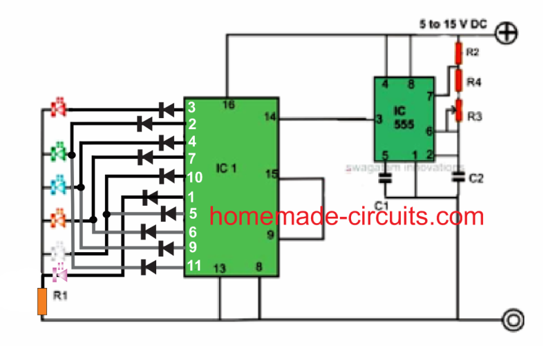
reverse forward LED light chaser  circuit diagram

How it Works

Looking at the shown reverse forward LED light chaser circuit, we see that basically the IC is arranged in its normal sequencing or chasing mode, however the clever introduction of the diodes at the outputs of the IC make the sequencing appear to be reversing and forwarding from start to finish and vice versa.

The smart arrangement of the diodes enables the output sequence of the IC to feed the LEDs in a way that the relevant LeDs are able to imitate a  to and fro chasing pattern.

This is achieved by by forcing  5 outputs to move in a forward chasing pattern, while the following 5 outputs are redirected toward the same LEDs but in the opposite direction, making the pattern look like a to and fro chasing motion.

Parts List for the proposed 4017 LED light chaser circuit

  • R1 = 1K,
  • R2 = 4K7,
  • R3 = 1K,
  • R4 = 100K pot, linear,
  • C1 = 10nF,
  • C2 = 4.7 uF/25V,
  • IC1 = 4017,
  • IC2 = 555

Adding More LEDs

In the above example we have seen how a reverse forward LED sequencing may ge implemented over 5 LEDs, however in order to get a more interesting effect we would want to increase the number of LED to higher numbers so that the illumination increases and the visual effect is able to get much enhanced.

The following section have explained how this may be accomplished using 200 LEDs, however any number of LED could be used just by modifying the transistors and the series parallel connections for the LEDs, I have explained the details.

Circuit Operation

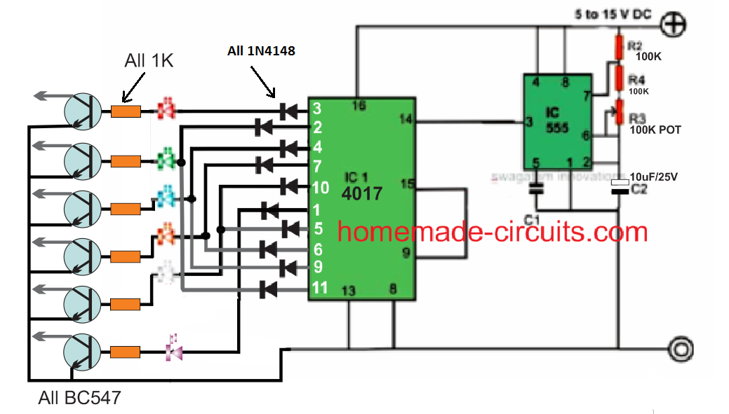
The circuit diagram shows a simple yet an effective configuration which is able handle up to 200 different colored LEDs and create the required to and fro chasing show.

The IC 4017 is the main part of the entire system whose outputs have been very cleverly manipulated using diodes.

Normally, in response to a clock signal the outputs of a 4017 IC would begin shifting sequentially from pin#3 to pin#11 covering ten of its pin outs in a certain random order.

If the LEDs are arranged in these ten outputs, one would acquire ordinary one direction sequencing of the LEDs.

In the discussed circuit, five of the end sequence pin outs have been diverted in such way that the connected LEDs produce a to and fro moving effect, however with this arrangement the total number of outputs get restricted to only 5, nevertheless sufficient for implementing the intriguing visuals.

Normally the outputs would accommodate a maximum of 4 LEDs, a total of 20 numbers. For handling as high 200 LEDs, transistor buffer stages have been included in the circuity.

Each transistor or the channel can hold upto 50 LEDs, the LEDs are connected in series and parallel combination as shown in the last diagram.

The LEDs are connected to the collector of the respective transistors as referred to in the last diagram.

The IC 555 is wired up as an astable for generating the required clock pulses at the input pin#14 of IC 4017.

These clocks determines the sequencing rate of the connected LEDs which may varied by adjusting variable resistor R3.

The circuit may be powered from a 12V battery or a 12V/3amp SMPS adapter unit.

Circuit Diagram with 200 LED Chaser Circuit
20 LED forward reverse chaser  circuit diagram

The basic reverse forward LED circuit using single LEDs can be studied elaborately  in this LED scanner article, and the video can be witnessed below:

How to Connect the LEDs

The following diagram illustrates the connection arrangement of the LEDs to the above circuit. A single series for each channel has been shown in the diagram.

The numbers can be simply increased just by inserting more such series in parallel to the respective strings of the different channels.

Circuit Diagram for Series Parallel LED Connections
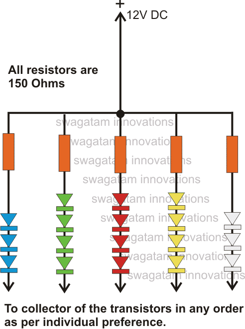
LED strings connected in parallel  circuit diagram

Parts List

  • R1 = 1K,
  • R2 = 4K7,
  • R3 = 1K,
  • R4 = 100K pot, linear,
  • C1 = 10nF,
  • C2 = 4.7 uF/25V,
  • IC1 = 4017,
  • IC2 = 555
  • All diodes are = 1N4007
  • All transistors are = BD139
  • All transistor base resistors are = 1K
  • LED resistors are = 150 Ohms 1/4 watt.
You'll also like:

  • delay ON timer compressedCube Light Circuits
  • car led bulb circuitHow to Make Car LED Bulb Circuit
  • SMPS LED Bulb Circuit with Dimmer Control using IC IRS2530D
  • 1 3Rotating Beacon LED Simulator Circuit

Filed Under: Lamps and Lights Tagged With: 100, 200, Chaser, Forward, LED, Reverse

About Swagatam

I am an electronics engineer and doing practical hands-on work from more than 15 years now. Building real circuits, testing them and also making PCB layouts by myself. I really love doing all these things like inventing something new, designing electronics and also helping other people like hobby guys who want to make their own cool circuits at home.

And that is the main reason why I started this website homemade-circuits.com, to share different types of circuit ideas..

If you are having any kind of doubt or question related to circuits then just write down your question in the comment box below, I am like always checking, so I guarantee I will reply you for sure!

Previous Post: « 18 LED Light Chaser Circuit Using Two Cascaded IC 4017 and IC 555
Next Post: LED Chaser Circuit with Blinker Effect »

Reader Interactions

Need Help? Please Leave a Comment! We value your input—Kindly keep it relevant to the above topic! Cancel reply

Your email address will not be published. Required fields are marked *

Primary Sidebar

My YouTube Channel

Circuit Simulator: Draw and Simulate Schematics

circuit simulator image

Categories

  • Arduino Projects (95)
  • Audio and Amplifier Projects (134)
  • Automation Projects (18)
  • Automobile Electronics (104)
  • Battery Charger Circuits (90)
  • Datasheets and Components (109)
  • Electronics Theory (151)
  • Energy from Magnets and Earth (43)
  • Games and Sports Projects (11)
  • Grid and 3-Phase (20)
  • Health related Projects (27)
  • Home Electrical Circuits (13)
  • Indicator Circuits (16)
  • Inverter Circuits (99)
  • Lamps and Lights (170)
  • Meters and Testers (72)
  • Mini Projects (28)
  • Motor Controller (68)
  • Oscillator Circuits (30)
  • Pets and Pests (15)
  • Power Supply Circuits (91)
  • Remote Control Circuits (50)
  • Security and Alarm (65)
  • Sensors and Detectors (107)
  • SMPS and Converters (46)
  • Solar Controller Circuits (62)
  • Temperature Controllers (44)
  • Timer and Delay Relay (51)
  • Voltage Control and Protection (44)
  • Water Controller (37)
  • Wireless Circuits (31)

Subscribe to get New Circuits in your Email

Other Links

  • Privacy Policy
  • Cookie Policy
  • Disclaimer
  • Copyright
  • Videos
  • Sitemap

People also Search

555 Circuits | 741 Circuits | LM324 Circuits | LM338 Circuits | 4017 Circuits | Ultrasonic Projects | SMPS Projects | Christmas Projects | MOSFETs | Radio Circuits | Laser Circuits | PIR Projects |

Recent Comments

  • Swagatam on Understanding Crystal Oscillator Circuits
  • Swagatam on Simple SG3525 Sine Wave Inverter Circuit Explained
  • Swagatam on Arduino SPWM Generator Circuit – Code Details and Diagram
  • सुधीर चौहान on Understanding Crystal Oscillator Circuits
  • Asif marth on Arduino SPWM Generator Circuit – Code Details and Diagram

Social Profiles

  • Twitter
  • YouTube
  • Instagram
  • Pinterest
  • My Facebook-Page
  • Stack Exchange
  • Linkedin

Calculators

  • ZVS Induction Heater + Tank Calculator Tool
  • Zener Diode Calculator
  • Wire Current and Thickness Calculator (Ampacity Calculator)
  • Voltage Divider Calculator
  • Transistor Base Resistor Calculator
  • Transistor Astable Multivibrator Calculator
  • TL431 Calculator
  • Solar Panel, Inverter, Battery Calculator
  • Ferrite Core Air Gap Calculator Tool
  • Parallel MOSFET Calculator Tool: How to Connect MOSFETs in Parallel Safely
  • LC Resonance Calculator for EV Battery Charger Circuits
  • LED String Series Resistor Calculator
  • PFC (Power Factor Correction) Calculator Tool: 3kW
  • Passive Power Factor Correction (PFC) Calculator
  • LM567 IC Calculator Tool
  • SMPS Flyback Boost Converter Calculator
  • Shunt Resistor Calculator for Ammeters
  • SCR and Triac Gate Resistor Calculator
  • Battery Back up Time Calculator
  • Boost Converter Calculator (Non-Isolated)
  • Bootstrap Capacitor Calculator
  • Buck Converter Calculator
  • Buck-Boost Converter Calculator
  • Capacitance Reactance Calculator
  • DCM Flyback Transformer & Wire Gauge Wire Size Calculator Tool
  • Filter Capacitor Calculator
  • IC 4047 Calculator (Frequency and PWM)
  • IC 4060 Calculator
  • IC 555 Astable Calculator
  • IC 555 Monostable Calculator
  • IC SG3525, SG3524 Calculator
  • Inductance Calculator
  • Induction Heater Inductor and Resonant Frequency Calculator
  • Induction Heater Work Coil Calculator
  • Inverter LC Filter Calculator
  • LC Resonance Calculator
  • LED Current Calculator
  • LM317, LM338, LM396 Calculator
  • NAND/NOT Gate RC Values Calculator
  • NOT, NAND Gate Frequency Calculator
  • Notch Filter Calculator Tool
  • Ohm’s Law Calculator
  • Phase Angle Phase Shift Calculator
  • Power Factor (PF) Calculator
  • RC Filter Calculator
  • Reactance Calculator
  • Sine Table Calculator for SPWM Arduino Code
  • Small Signal Transistor(BJT) and Diode Quick Datasheet
  • SMPS Calculator for Toroidal Ferrite Transformers
  • SMPS Flyback Transformer Calculator – Design by Target Duty Cycle
  • TL431 Calculator
  • Op-Amp Hysteresis Resistor Calculator

© 2026 · Swagatam Innovations