 Homemade Circuit Projects

In this post I will explain two different LED sequencer circuit designs, one using the IC 74C164 and the other using IC 74LS164. Even though both these ICs share the exact same logical function, meaning both are 8-bit Serial-In Parallel-Out (SIPO) shift registers with identical pinout configuration, but yet they belong to completely different integrated circuit families.
Using IC 74C164
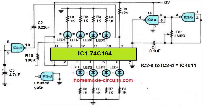
Referring to the 74C164 based chaser circuit diagram below, we can see a low-frequency, astable oscillator circuit, made up of two gates, IC1a and IC1b, from the IC 4011 quad two-input NAND gate.
How the Circuit Works
The operating frequency of this astable is determined by the values of C1 and R11. This circuit configuration works well as a clock-pulse generator for feeding the IC1's 74C164 shift register. The positive output pulses from the clock at pin 4 of IC2 are supplied into the shift register's clock input at pin 8 of IC1.
Each output of the shift register is wired to an LED. Each LED is connected to a 1K current-limiting resistor in series.
The input of gate IC2c is connected to the eighth output of the shift register, located at pin 13, via a time-delay RC configuration comprised of R10 and C3.
The output of the gate is connected to the clear input of the shift register at pin 9 through a capacitor. LED8 is turned on by the eighth clock pulse, and C3 is charged as soon as pin 13 of IC1 becomes positive.
After a little delay, the output of IC2c becomes low, clearing the outputs of the shift register.
The LEDs light up in the following sequence: LED1 is turned on by the first clock pulse, LED2 by the second, and so forth until all eight LEDs are illuminated.
The clear pulse from IC2c shuts off each LED once the eighth LED illuminates, and the process is then repeated.
R10 and C3's values can be changed to make LED8 stay on for the identical amount of time as the remaining LEDs.
For a quicker sequence, the RC time delay circuit must be smaller; and for a slower series, it must be larger. Increasing the value of R10 or C3 will shorten the delay period, and decreasing the value will extend the delay time.
Using 74LS164 IC (LED Scanner Effect)
In next idea is also a chaser circuit using the IC 74LS164, which produces a LED scanner type illusion through the various sequencing illumination modes over the attached LED arrays. The idea was requested by Mr. Danely Sooknanan.
Technical Specifications
I want to build the new Knight rider mustang light for my car scoop.What i have read is. It's made up out of 480 distinct LEDs, arranged in three rows of 80 in each row, then divided up into two sides.
My question is how you build it. The size i want to work with is 12 inches in length by 1/2 inch in width. How many rows of leds will i get by that dimension. What kind of led to use? What can i use for the diffuser case? What to use for the control box.
The Design
In the actual knight rider LED scanner unit as shown in the video, there are as many as 29 number of functions to be precise, implementing those is virtually impossible using discrete components and without employing MCUs, however here we'll see how a few of these could be possibly made using just a handful of components.
The main two functions of the proposed Mustang LED scanner circuit may be assessed as given in the following description:
1) LEDs light up in a bar mode fashion from the two ends of the strip and meet up at the center, illuminating the whole module brightly.
In the next sequence the LEDs begin shutting off in the same sequence as above from the outer extreme ends until all the LEDs are switched OFF.
The rate or the speed of the above procedures are adjustable through a pot as per individual preferences.
2) The second scanning sequence is similar to the above, except the shutting off procedure which is done for all the LEDs at once instead of one at a time.
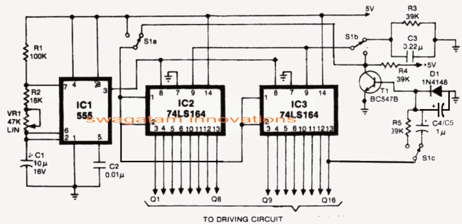
The above two functions can be easily implemented using a couple of 74LS164 ICs and a 555 IC oscillator as shown in the following circuit diagram:
Circuit Diagram
Looking for a Meteor Shower LED Effect Circuit? Please check out this article
How 74LS164 Works as the Controller
In the shown mustang scanner LED light circuit, a couple of 8-bit parallel-out shift register ICs 74LS164 are employed, driven by the IC555 configured as the clock oscillator.
The circuit may be understood by considering the following two modes in the design:
As may be seen in the above circuit diagram, a 3 pole, 9 throw switch is used as the changeover switch for imitating the 2 functions explained in the previous section above.
In mode1 S1 is connected as shown in the circuit diagram, in this position the LEDs illuminate in an sequencing LED bar like fashion with every rising edge of the clocks from the IC555 until all the LED light up and the final "high" reaches pin16, when T1 momentarily resets both the ICs producing in instant shutting off of all the LEDs at once.
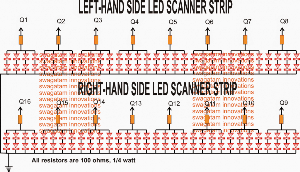
In the actual prototype the LEDs from Q9----Q16 must be arranged such that Q16 faces Q8, while Q9 faces the outer end of the relevant strip.
As soon as the above happens, a new cycle initiates afresh and the cycle repeats for so long as the S1 position isn't changed.
Mode#2
In mode 2 let's consider the switch S1 connected with the positive supply, thus S1a gets connected with the +5V line, S1b gets hooked up with the collector of T1 while S1c with R5. Also the reset pin 9 of IC1 and IC2 get connected with the collector of T1 whose base can be seen configured with the last output Q16 of IC2.
On power switch ON, the LEDs begin illuminating in a BAR like mode as before from Q1 to Q8 and from Q9 towards Q16 in response to each clock pulses supplied by the astable IC 555 at pin8 of the two 74LS164 ICs.
Now as soon as the high across the shifting outputs reach pin 16, T1 instantly inverts and renders a low to the serial pins 1, 2 of the ICs so that now the LEDs begin shutting off one by one across the arrays in the same sequence as it illuminated in response to every clock from IC 555.
The LED Sequence Keeps Recycling
The procedure keeps repeating as long the switch S1 position is not changed from its existing position.
The above two functions are pretty easily implemented and we have our LEDs scan the whole array quite in the manner the actual Mustang scanner is supposed to do.
However with the above two functions the features look much limited and we would want to insert a few more of the features as may be witnessed in the original video.
I'll keep the article updated with the new added features, but in the meantime I have explained how the LEDs could configured to the above scanner design as per the request made by Mr. Dannel. For ease of calculation and configuration we incorporate 32 + 32 LEDs on each left and right strips.
The arrangement and the connection details may be verified through the following diagram:
Enabling Rapid Up/Down Sequence
Another interesting scanner function that could be easily added to the above circuit with a feature producing rapid to and fro sequencing over the two strips in groups of four.
This could be easily done by toggling an arrangement wherein T1 would freeze once all the LEDs switch ON in bar like style.
Now in this position a 4017 with its own oscillator would come into the scene with its outputs switching OFF the lit LEDs rapidly in a reverse forward manner. The switching could be done using BJTs which would ground the relevant anodes of the LEDs in the process.
So now we have three interesting scanning sequences toggled in our very own homemade mustang LED scanner circuit, any more possible solutions are welcome from the readers.




Need Help? Please Leave a Comment! We value your input—Kindly keep it relevant to the above topic!