In this post I have explained the construction of a ultrasonic directive speaker system also called parametric speaker which may be used to transmit an audio frequency over a targeted spot or zone such that the person situated exactly at that spot is able to hear the sound while the person next to him or just outside the zone stays completely untouched and unaware of the proceedings.
Invented and built By Kazunori Miura (Japan)
The outstanding results obtained from the testing of Long Range Acoustic Device (LRAD) inspired the American Technology Corporation to adopt a new name for it and was changed to LRAD corporation on March 25th 2010. Also called the Audio Spotlight, it is a product of Holosonic Research Labs, Inc and is used for non-military applications.
The device is designed to generate intensely focused sound beams over a targeted area only. The unit may be well suited in places such as museums, libraries, exhibition galleries where its sound beam may be used for sending a warning message or instruct a particular mishaving person, while others around are allowed to carry on in perfect silence.
The focused sound effects from such a parametric speaker system is so accurate that anybody who is targeted with it becomes hugely surprised to experience the focused sound content which is heard only by him while the guy just beside him stays completely unaware of it.
Working Principle of a Parametric Speaker
Parametric speaker technology employs sound waves in the supersonic range which have the characteristic of travelling through almost the line-of-sight.
However one may wonder that since supersonic range may well be beyond the 20kHz mark (40kHz to be precise), could be absolutely inaudible to human ears, so how does the system is able to make the waves audible in the focused zone?
One method of implementing this is to use a two 40kHz beams with one having an audio frequency of 1kHz superimposed and angled to meet at the directed point where the two 40kHz content cancel each other leaving the 1kHz frequency audible at that particular spot.
The idea may look simple but the result could be too inefficient due to the low volume sound at the directed spot, not good enough to stun or incapacitate the targeted people, quite contrary to the LRAD.
Other modern methods of producing audible directive sound using supersonic waves are through amplitude modulation (AM), double sideband modulation (DSB), single sideband modulation (SSB), frequency modulation (FM), all concepts depend on the recently researched parametric speaker system technology.
Needless to say, a 110 dB+ supersonic wave could be nonuniform with its sound force distribution while it's in the course of propagation across a long air mass "tube".
Due to the non uniformity of the sound pressure an immense amount of distortion could be experienced which could be highly undesirable for applications in peaceful places such as in museums, galleries, etc.
The above non-linear response is produced due to the fact that air molecules take relatively more time to arrange themselves to their previous original density compared to the time taken for compressing the molecules. Sound created with higher pressures also results in higher frequencies which tend to generate shock waves while the molecules collide with the ones being compressed.
To be precise since the audible content is constituted by the vibrating air molecules that are rather not entirely "returning", therefore when the frequency of the sound increases, the non uniformity forces the distortion to become much audible due to the effect which could be best defined as "air viscosity".
Therefor manufacturer resort to the DSP directive speaker concept which involves much improved sound reproduction with minimum distortion.
The above is complemented with the inclusion of highly advanced parametric transducer speaker arrangement for getting an unidirectional and clear sound spots.
The high directivity created by these parametric speakers is also due to their small bandwidth characteristics which could be enlarged as per the required specification by simply adding many number of these transducers through a matrix arrangement.
Understanding Parametric 2-Channel Speaker Modulator Concept
DSB could be easily executed using analogue switching circuits. The inventor initially tried this, and though could achieve a loud sound, it accompanied with a heck lot of distortion.
Next, a PWM circuit was tried, which employed the concept akin to FM technology, although the resultant sound output was much distinct and free from distortion, the intensity was found to be a lot weaker compared to DSB.
The drawback was ultimately solved by arranging a double channel array of transducers, each array including as many as 50 numbers of 40kHz transducers connected in parallel.
Understanding the Audio Spotlight Circuit
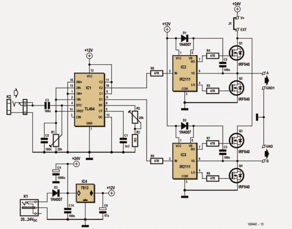
Referring to the parametric speaker or ultrasonic directive speaker circuit shown below we see a standard PWM circuit configured around the PWM generator IC TL494.
The output from this PWM stage is fed to a half bridge mosfet driver stage using the specialized IR2111 IC.
The IC TL494 has a built-in oscillator whose frequency could be set through an external R/C network, here it's represented through the preset R2 and C1. The fundamental oscillating frequency is adjusted and set by R1, while the optimal range is determined by appropriately setting up R1 and R2 by the user.
The audio input which needs to be directed and superimposed on the above set PWM frequency is applied to K2. Note that the audio input must be sufficiently amplified by using a small amplifier such as LM386 and must not be sourced via headphone socket of an audio device.
Since the output from the PWM stage is fed across a twin half bridge IC set up, the final amplified supersonic parametric outputs could be achieved via two outputs across the shown 4 fets.
The amplified outputs are fed to an array of highly specialized 40 kHz piezo transducers via a optimizing inductor. Each of the transducer array may consist of a total of 200 transducers arranged through a parallel connection.
The mosfets are normally fed with a 24V DC supply for driving the piezos which may be derived from a separate 24V DC source.
There could be a host of such transducers available in the market, so the option is not limited to any specific type or rating. The author preferred 16mm diameter piezos assigned with 40kHz frequency spec typically.
Each channel must include at least 100 of these in order to generate a reasonable response when it's being used outdoors amidst high level of commotion.
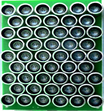
Transducer Spacing is Crucial
The spacing between the transducers is crucial so that the phase created by each of them is not disturbed or cancelled by the adjacent units. Since the wavelength is mere 8mm, positioning error of even 1mm could result in a significantly lower intensity due to phase error and loss of SPL.
Technically, an ultrasonic transducer imitates the behavior of a capacitor and thus it could be forced to resonate by including an inductor in series.
We have therefore included an inductor in series just to achieve this feature for optimizing the transducers to their peak performance limits.
Calculating Resonant Frequency
The resonant frequency of the transducer may be calculated by using the following formula:
fr = 1/(2pi x LC)
The internal capacitance of the 40 kHz transducers could be around 2 to 3nF, thus 50 of them in parallel would result a net capacitance of about 0.1uF to 0.15uF.
Using this figure in the above formula we get the inductor value to be in between 60 and 160 uH which must be included in series with the mosfets driver outputs at A and B.
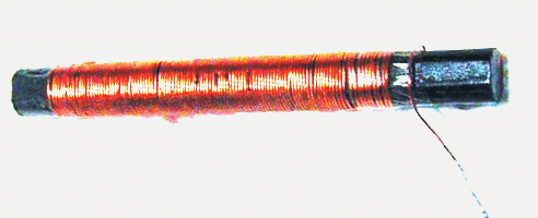
The inductor uses a ferrite rod as may be witnessed in the figure below. The user could peak up the resonant response by adjusting the rod by sliding it within the coil until the optimal point could be struck.
Circuit Diagram
Circuit idea courtesy: Elektor electronics.
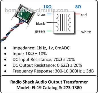
In my prototype I experimented with an audio transformer as shown below for the required amplification, with a single common 12V supply. I did not use any resonant capacitors therefore the amplification was too low.
I could hear the effect from a distance of 1 feet exactly across a straight line with the transducer. Even a slight movement caused the sound to disappear.
Speaker Inductor (Small Audio Output Transformer):
How to Connect the transformer and the transducers
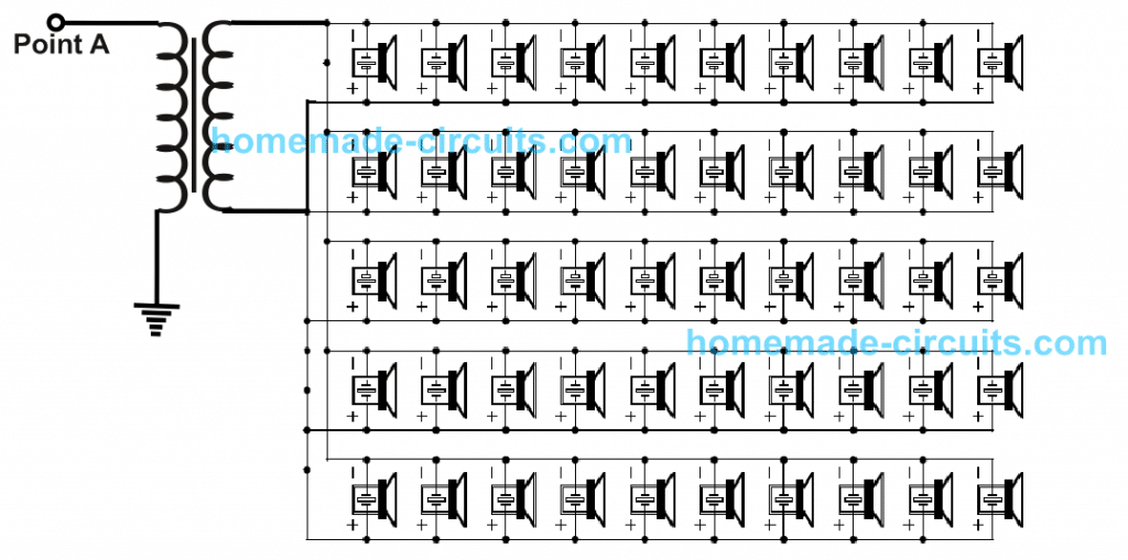
Transducer wiring details can be seen in the below given figure, you will need two of these set-ups to be connected with points A and B of the circuit.
The transformer can be suitable step up transformer depending on how many transducers are selected.
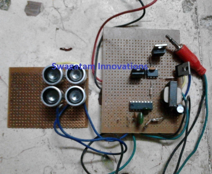
Prototype Image: The above parametric speaker circuit was successfully tested and confirmed by me using 4 ultrasonic transducers, which responded exactly as specified in the article explanation. However, since only 4 sensors were used the output was too low and could be heard only from a meter away.
Caution — Health Hazard. Appropriate measures must be taken to prevent long term exposure to high ultrasonic sound levels.
Original Document can be Read Here


Questions & Answers
Sir, if time allow please elaborate on TV Antenna to get few channels free. Google showing many result but all are for out of India. Please show light on this topic and also the tv ballon which convert 75 to 300 Ohm
Ram, I'll try to get the required info, if i get any will post it for sure.
Is this circuitry working? have some one tried it? is some 1 having issues??
i have tried it, it works…however since I used only with 4 tranducers the output was too low….but the directive feature definitely worked.
Sir how to connect array of transducers to the circuit…do we need to connect audio transformer before array of transducers
Oh thats good!.. Thanks Swagatam for your reply, If I need any assistance regarding the circuitry will you help me out?
sure, I'll try my best!
I have some Qs: 1. Capacitor 1 = 3n3 what is this? is ot 33 nF of 3 nF?
2. Is there any alternative for IR2111 that can be used for the same circuitry?
Thanks for the response
3n3 = 3.3nF
I had used the same IC, so not sure about a replacement for it.
Try googling for "half bridge mosfet driver IC" you could come across a few possible equivalents and modify it to suit the requirement.
Can you please guide of how much transducers should I use to have a nominal volume of sound? like a person if 2 meter or less away be easy to hear the spot light sound ?
it'll be difficult to suggest without a practical testing, because i used just 4 and could get a very low output
please guide if I use 10 piezos each side what will be the inductor value used for this ciruitry?
According to calculation the range will be 300 to 800 uH
Please make me correct if I am wrong!
C in the formula should be in Farads, so the capacitance should be first converted to farads from uF first for getting correct results.
It's better to check it manually by shifting the ferrite rod to and fro and optimize for the best possible results.
please guide me that you have used 2 variable resistors please tell me the value of resistor i need to set for this circuitry ??
halai, please click the diagram to enlarge it, you will find all the details in the diagram itself.
wat about spacing between transducer. and i m mot getting ferrite core inductor in market with need value..
spacing example is shown in the first image, make the inductor by hand as shown in the second last diagram
My circuitry not working please guide
Here: At TL494 : my pin 3 is open
IR2111: pin 5 is open
inductor i have used of 680 uH(fixed value not hand made) value with 5 Piezos
Please tell me why isn't it working?
halai, initially do not use both the IR2111 stages, use only one stage, once it gets confirmed, then you can build the second IR2111 stage for doubling the power.
Instead of using an inductor, i recommend using an audio transformer, as shown below, it will provide an instant amplification without going through any adjustments or complexities:
beavishifi.com/projects/Passive_IPOD_Preamplifier/Radio-Shack-Audio-Transformer.jpg
connect red/white across the mosfet junction and ground….use the secondary outer taps for connecting with the transducers…ignore the center tap.
here's another image of the same:
sci-toys.com/scitoys/scitoys/radio/hand_xformer.jpg
Hey Swagatam, may you explain to me, why the volume all in all depends on the spacing of the speakers?
The wavefront of the speakers should just depend on the speakers beeing in phase, I'd say. And there the spacing doesnt matter.
I could just guess, that you need to have a multiple of lambda between the centerpoints of 2 speakers, but I dont see why?
Can you help?
Hi Peter,
the spacing between the speakers is crucial because if they are too wide apart, the waves will not be able to concentrate over a smaller area and weaken itself.
If the speakers are kept too close, the waves might interact with each other creating interference which might yet again affect its focusing ability
Sir, can you please share your work by photograph or video?
It was built a long time ago by me, and later was dismantled for some other use
I don't see how you end up with the right values with the equation you have provided for the LC part.
I have a few boards here with working parametric speakers and the values for the coil seem to be off as far as the capacitance value for the emitters
For example
I've worked backwards from the versions of the boards I have here with the inductance values I can clearly see on all of the different types I have.
inductance values on the boards I have and the relationship to the calculated capacitance values are
98 x 16mm Ultrasonic elements, uses a 25uH Coil = 633553pF / 98 = 6464 pF each
50 x 16mm Ultrasonic elements, uses a 49uH Coil = 323241pF / 50 = 6464 pF each
OK so that makes sense because its almost half and we end up with the same cap values
What doesn't make sense is each of the elements are listed as having a cap value of approx 2700pF – (6464pF is almost double)
So how did you arrive at your conclusion
The idea is not mine, it is as per the original inventors write up.
In my experiment I used an audio transformer for amplifying the frequency…I connected the primary across the mosfet outputs and connected 6nos of 40kHz transducers across the secondary of the trafo, and tweaked the relevant pots to optimize a reasonably good parametric effect, although the audible power was too low, that may be because I had used only 4 of the transducers and not 100 or 200 as recommended above
Hi swagatam
Can you please assist me with this circuit ? I am confused about the audio input to the circuit , i must add an lm386 op amp but i am not knowing how to connect it to the circuit .
Audio input should be applied across C2 end and ground…connect the output from the LM386 with C2, and make the negative or the ground of the LM386 common with the above circuit.
Hi swagatam .
I am a bit confused about this circuit because it is not working . I suspect that the problem is from the audio input . Can you please help with this issue and tell me how to connect the audio input from a device to the lm386 op amp and to the circuit ?
Thank you
Sir, I am searching for the details of speaker required to make a unidirectional sound system using a 24" Dia polycarbonate cleat dome.
Vijayan, use ultrasonic transducers as explained in the above article.
can please list the components you used in the circuit you gave and is this battery powered if not how would i adapt the circuit.
please click the diagram to enlarge, you will be able to find the part numbers marked beside the symbols.
you can use a lead acid battery or an smf battery to operate this circuit
Dear Mr Swagatam Majumdar,
I would like to know that, the circuit could me modified in a way such that a switch produces a sound(like an horn).
Please do share your thoughts on the modification
Thanking You
Dear Nithin, you will have to feed a horn frequency at the input of the above explained circuit to get a directive horn sound on the selected spot.
Since I am a noob…is it possible to explain how to input horn frequency??
Nitin, if you are a noob then I am afraid you won't be able to build the above circuit in the first place…
making the horn circuit will be easy but making the above directive circuit can be much difficult…so first try to successfully finish the above design then we can proceed with the horn circuit.
Sir….obviously i have help…..as you said i will first finish the directive speaker first….but thanks for your help….i have grasped on what you have said
you are welcome!!
Sir…on what board did u mount your transducers on??….
On PCB or printed circuit board
Hello
I seem to be having a problem. I can't hear any music from ultrasonic transducers even after connecting the audio source (which is the music player of my smartphone).
However, I can hear the initial sound when ultrasonic transducers are activated after connecting the power supply.
The audio jack has no problems.
I have included only one channel (IR2111 connected to pin 10 but not pin 9 of TL494). Power supply is 24v.
Please help. I'll be happy to provide further details, if required.
Hello
I seem to be having a problem. I can't hear any music even after connecting the audio source (music player of my smartphone). The 3.5mm audio jack that I'm using is not damaged.
However, I can hear the initial sound when ultrasonic transducers are activated after connecting the power supply, which is 24V.
I have included only one channel (IR2111 connected to pin 10 but not pin 9 of TL494).
Please help. I'll be happy to any provide further details, if required.
Hello, how many transducers did you use?
In my prototype I had used just a couple of them, and I could hear hardly anything when my ears were positioned precisely in line with them…and that's exactly how it should work…unless your ears are in line with the transducer assembly axis you are not supposed to hear anything.
try positioning one of your ears in line with the transducer assembly and you might certainly be able to hear the sound, albiet at a very low volume.
To hear it at louder volumes you may have to employ 50 to 100 transducers as instructed in the above article
…and please note that you will also have to optimize the pots/presets correctly for achieving the most favorable sound quality and volume.
I have used 16 transducers (16mm,40kHz), all connected in parallel as shown above.
Yes, I could hear a low volume distorted sound from the transducers as soon as they are supplied power.
Strangely, it is this same distorted sound that is coming out from the transducers even after providing an audio signal (to 3.5mm audio jack socket via an audio cable)
Setting the pots simply varies the sound quality of the distorted sound.
I had used only two transducers and I could hear the sound at very low volume, I had to bring my ear at around 4 inches near the transducers and in line with it to hear the music….shifting away from the line instantly made the audio disappear.
however the music in my design was pretty clear after some optimization of the pots.
you can try replacing the inductor with an audio transformer and see if that helps in increasing the volume…I had used an audio transformer in my prototype.
The speakers are working fine with the inductors (I'll also try with audio transformer). I guess the main problem lies in the PWM circuit.
The circuit that I have built contains a 3.5mm audio jack socket for audio input signal.
The outer 2 pins i.e tip & ring (see picture) are tied together and connected to one end of 0.1uF capacitor.
The other end is connected to pin 4 (DTC) of TL494.
Sleeve pin is grounded.
Despite the circuit being as per the schematic, no music can be heard on connecting a 3.5mm jack audio cable.
in that case you can try removing the jack and connect the wires directly with the input of the amplifier.
you can also try any other form of class D amplifier for the same, there are many Hi-Fi class D amp circuits online which can perhaps tried for the purpose…
sir….is your c4 and c6 Polarized Capacitor?
yes….