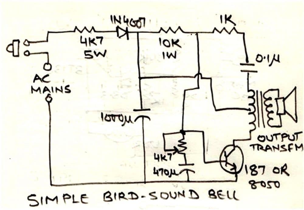
The diagram presented below shows a simple circuit of a bird chirping sound generator. All the parts are very common and the transformer is an ordinary type as found in small transistor radios at the output stage
Circuit Operation
The circuit is basically a feedback oscillator circuit that is configured around a small output transformer. The transistor forms the main active components here.
When mains power is applied to the circuit, the 4K7 resistor resists the voltage and drops it to lower levels suitable for operating the DC electronic circuit.
The diode rectified the low level AC to DC while the capacitor filters and smoothens the rectified DC.
Initially the voltage reaches the base of the transistor which instantly conducts and pulls the one half winding of the transformer to ground, forcing a strong induced current across the secondary winding.
However the moment this happens, the entire voltage is shorted to ground via the transformer winding and this eliminates any biasing voltage at the the base of the transistor and it fails to support the conduction.
The transistor releases the transformer activation which reverts a strong back emf to the secondary winding.
However the moment the transistor stops conducting, the voltage at it's base is restored and the cycle repeats again.
This repeated pulsation of the transformer induces a strong back emf oscillation at the secondary of the transformer, which is amplified over the connected loudspeaker.
The associated components, the 10 resistor and the 0.1 capacitor performs the feedback function for keeping the transistor active with a certain foxed frequency range.
The frequency of the circuit may be adjusted through the 4k7 pot and the 0.1uF capacitor so that any desired tone can be achieved at the output over the speaker.
The above adjustments helps to refine the tone of a particular bird to any form and helps to replicate the results as closely as possible.
Warning: The following circuit is not isolated from mains AC, and is therefore extremely dangerous to touch in open and switched condition. Extreme precaution is advised while handling this circuit.
Parts List
- Resistors
- 4.7 k 5 watt = 1
- 10 k 1 watt = 1
- 1 k 1/4 watt = 1
- preset, trimpot 4.7 k = 1
- Capacitors
- 1000 µF, 50 V = 1
- 470 µF, 25 V = 1
- Ceramic Disc 0.1 µF = 1
- Transistor 8050 = 1
- Audio Output Transformer = 1
- Push button = 1
220 V Bird sound Chirping Effect
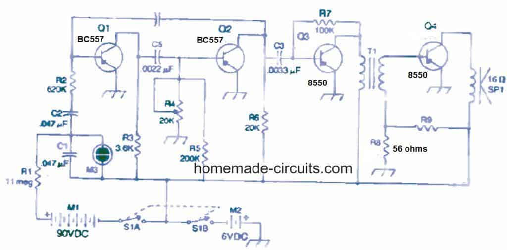
The 220 V AC based "chirper" circuit sounds exactly like a bird. It offers a control which you can use to vary the tone of the fundamental sound output through lower frequencies to higher.
When the speaker (4 to 6 inch should be adequate) is installed within the exact same box along with the circuitry, it can decide the complete scale the device.
Essentially the circuit is actually a free-running multivibrator. Pot R4 adjusts the frequency from around 1000 hertz to 10,000 hertz.
The bird chirping effect is achieved by a low-frequency oscillator applying a neon bulb (M3).
This signal supplies base bias for transistor Q1. In case capacitor C1 is short circuited, the chirping effect is removed, and the circuit turns into a easy variable-frequency multivibrator.
Transistor Q3 works like the driver stage, and Q4 is rigged as the output transistor.
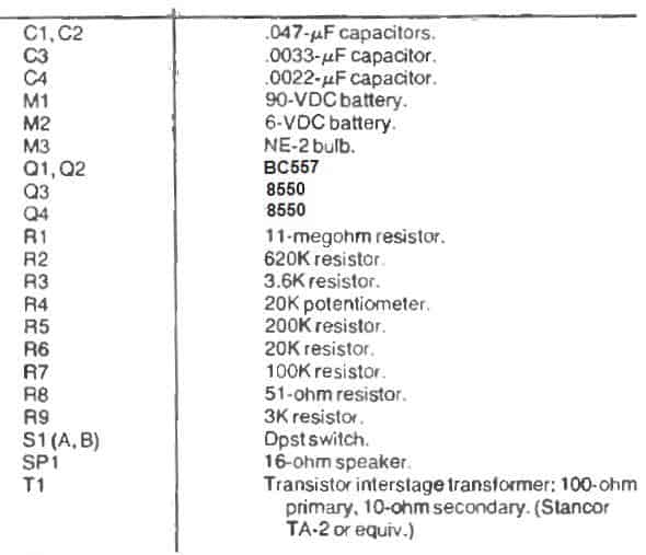
Parts List
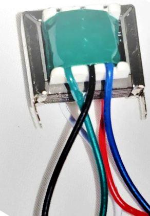
T1 can be any standard audio output transformer as shown below:
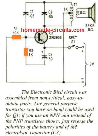
Another Simple Bird Sound Generator
Wide Range Bird Sound Simulator
The bird simulator circuit explained circuit is build with three relaxation oscillators and one decade counter. The oscillators are all configured like astable multivibrators.
The AMV1 to 3, are both configured around a a couple of CMOS logic inverters.
Oscillator AMV1 functions with a frequency which may be a small percentage of a hertz. This frequency is employed for providing the clock pulses to the counter IC2.
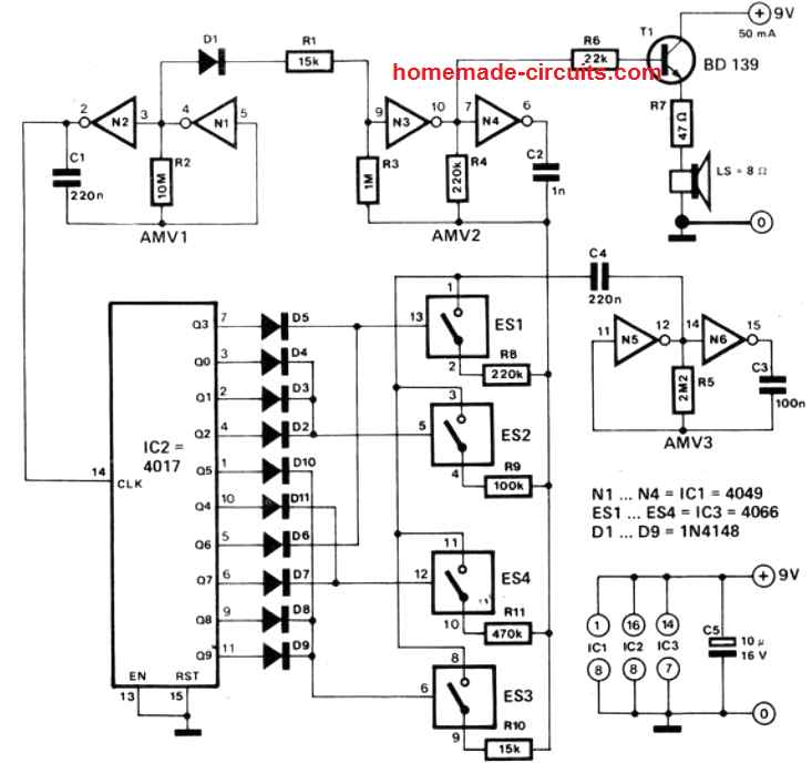
For so long as the counter remains activated, a logic 1 moves across the outputs Q0 to Q9 exactly in accordance with the rhythm with the clock pulses.
The AMV2 oscillator can be expected to imitate the vocal chord of a bird, since it generates an high-frequency note resembling a bird sound. The AMV3 oscillator becomes responsible for delivering a wide range of frequencies that modulates the AMV2 output.
This is implemented in such a way that the ultimate output simulates exactly a real bird sound, not like the one that you hear from electronic chimes.
The frequency created from the AMV3 oscillator is determined by the value of resistance connected between the capacitor C4 and resistor R4.
To be more precise, it is resistor which is switched between R8 and R11.
The switching of these resistors is implemented by CMOS switches ES1 ES4, governed by the many different combinations from the counter outputs.
This particular set up guarantees that the ultimate output is randomly created, and sounds like a real bird and not a monotonously reproducing noise.
The circuit includes a wide variety of rich bird sound customization options.
Remember that it is always possible to alter the resistors R8----R11 values, along with the counter circuit output combinations, with the connections to electronic switches ES1 ES4, in order to customize the bird sound to any desired effect.

Questions & Answers
Dear friend,
I don’t get the output transformer. Hence can you suggest circuit without audio transformer?
Hi Parimal,
Sorry, but the above circuit will require an output transformer, without that the circuit won’t operate.
Other alternative is to use an Arduino nano and drive a speaker directly through a transistor at its output.
If you want to do that, I can provide you the Arduino program code…
Hello sir, can you make a circuit that can speak words in human sound and convert them into parrot sound
Hello Shishpal,
It may be roughly possible by using Arduino with ISD1820 + pitch changer circuit
Hello, I am interested in the circuit “Wide range bird sound simulator” is this assembly to scare birds away in my cherry tree.
Sincerely Perin.
Sure, you can build it, please go ahead.
Hi Swagatam,
It appears you received my email as you posted the cricket chirp schematic. Have you had time to review it to see if it can be modified to do its cricket sound once or twice and then be silent for 5 to 10 minutes and then repeat? I’m not pressuring you, I just want to know if you are considering it. Thanks!
Hi Norman, I have already answered you in the following link with a solution. please check it.
https://www.homemade-circuits.com/cube-light-circuits/
Hi Norman, my email is in live.in not in wordpress, please search your previous email which you had sent me….or you can upload the schematic to any free online image hosting site, and provide the link to me here…
Hi Swagatam,
I found this circuit on the internet and it works. I would like to modify it to chirp once and then be silent for 5-10 minutes and then repeat. I tried several things without success. Please help! IC1 is 4093 and IC2 is 4060.
R1=330K, R2=220K, R3,R6=100K, R4=OPTIONAL LDR, R5,R7=22K, R8=10K, R9=470R TRIM POT, R10=22R
C1,C2,C3=47uF, C4=10uF, C5=1uF, C6=10NF, D1,D2,D3,D4=1N4148, Q1=BC547, IC1=4093, IC2=4060
Dear Swagatam
Hello. Thank you for reply Sir.
Emaad
You are welcome Emaad!
Dear Swagatam
Hello. Please tell me if the amounts of 2 NON POLAR?? C1 and C2 are 0.02 and 0.05? ( in your first diagram: Another Simple Bird Sound Generator )
Thanks in advance
Emaad
Hello Emaad, C1 = 0.02uF, C2 = 0.05uF ceramic disc capacitors
Give alternative diagram as radio transformar is not available in market.
Presently I don’t have it, will try to search and update it here
Earlier two transformers (t1 & t2, used in Hitachi radio circuit) were used, but in this ckt only one transformer. Can I use pocket radio driver transformer (bell silicon circuit)?
Because this is not a radio but a simple oscillator amplifier, yes you can use the audio transformer from any pocket radio
Dear Swagatham
I have assembled this type of circuit before 20years. The bird chirping sound is very pleasing.
Bot, now a days the output transformer is difficult to get in our local area. (I am sure, it is available in Online.)
So, cian you please re design the circuit using a 3V-0-3V or 6V-0-6V/500mA secodary, 220V primary transformer instead of the audio output transformer.
Thanks in advance.
Dear Anil, you can use a step down transformer without any changes to the circuit. We just have to make sure that the transformer primary specs and the circuit supply specs are matching, meaning if the circuit is designed work with 9V then use a 9-0-9 transformer and so on.
In this design since a 4k7 resistor is used for dropping the current, any low voltage transformer should work…a 3-0-3 or a 6-0-6V all should work with minor difference in the output volume
Dear Swagatham,
No, no…no. You may not understand my question well. I am just asking about the tranformer that connected the speaker in your circuit.
Can a 3V-0-3V or 6V-0-6V/220V stepdown transformer use in place of the OUTPUT TRNSFORMER with minor or major modifications in the circuit….?
Hi! You could use the 9-0-9 for transistor side and the 115 or 230 side connected to the 115 or 230 side of a second transformer and the speaker in its 9-0-9 side.
Dear Anil, yes you can do it without any changes to the circuit. The size and weight of the transformer will be the only issue here.