• Skip to main content
  • Skip to primary sidebar

Homemade Circuit Projects

Get free circuit help 24/7

New Projects | Privacy Policy | About us | Contact | Disclaimer | Copyright | Videos 

You are here: Home / Audio and Amplifier Projects / Public Address (PA) Amplifier Circuit

Public Address (PA) Amplifier Circuit

Last Updated on January 5, 2023 by Swagatam 2 Comments

A public address system (PA system) is an electronic system that includes a set of audio electronic devices such as microphones, amplifiers, loudspeakers, and other similar audio equipment. It is designed to boost the volume of a human speech, or a musical source, or some other audible sound input to an amplified version through an attached loudspeaker.

caution electricity can be dangerous

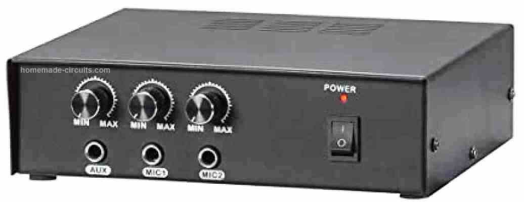
PA systems are normally employed in different public areas that calls for an human speaker, artist, etc. to be loudly audible over a substantial distance so that the speech of the person using the PA system becomes audible to a large gathering or crowd. Common places where a PA system can be used are sports stadiums, public vehicles, and live rock and music venues, and occasions.

A PA system can consist of several microphones or additional audio sources, an audio mixer unit which are able to blend and customize the audio signals coming from the various sources, and amplifiers. The output is subsequently fed to a loudspeaker for getting an amplified volume, resulting in a wider distribution of the sound.

How the Circuits Works
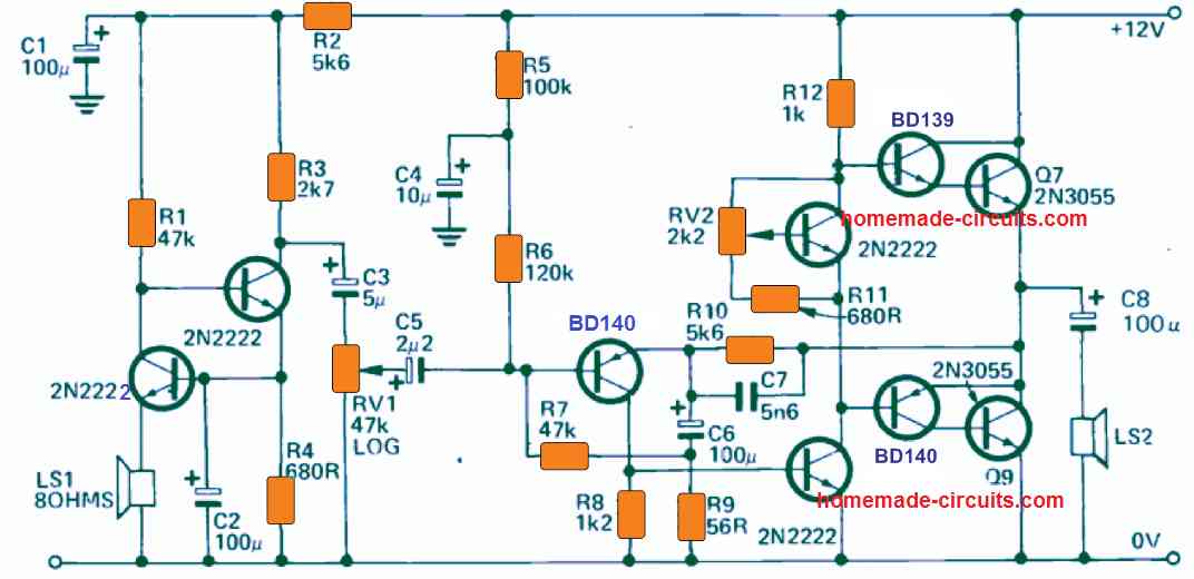
The proposed public address circuit explained in this article works with a small speaker, whose impedance is unimportant. This speaker is hooked up across the emitter of Q1.

The above tiny speaker is used like a microphone, where the user needs to speak for getting his voice amplified.

Q1 is configured in the common base format which causes an extremely increased signal to be generated and fed across its collector.

Transistor Q2, is wired up in the common emitter configuration. Q2 is used for increasing the amplification further. The audio or the speech signal from the collector of Q2 is applied by means of the C3 which acts like a blocking capacitor to VR1, configured like a volume control.

The general de-stabilisation is achieved by having the base biasing of Q1 through the emitter of Q2.

The design of this public address power amplifier circuit is reasonably standard and is configured using a robust looking output stage.

This strong output stage is employed so that the amplifier is able to drive a couple of large P.A. type horns in parallel.

With these types of load at the output we can expect an output power of 8W over the horns or the speakers.

Because the public address or PA amplifier circuit is supposed to be used for amplifying mostly the human speech, a wide bandwidth specification is not important.

Therefore, the capacitor C7 is included to roll off any frequency response that may appear over the 5kHz range. The capacitor C6 is additionally employed for delivering a fast roll off around the bass frequency region.

Power transistors Q7 and Q9 must be installed with a 5" x 4" finned type heatsink. Make sure the body of the transistor Q4 remains thermally in contact with the heatsink.

You'll also like:

  • 1.  Simple LED Music Level Indicator Circuit
  • 2.  Audio Dithering Circuit for Enhanced Crisper Music
  • 3.  Extended High Bass Effect from Small Speaker Box [Cross-Over-Filter]
  • 4.  Make this Simple Music Box Circuit
  • 5.  Build this Subwoofer Amplifier Circuit [Mini Ground-Shaker]
  • 6.  Tuned Radio Frequency (TRF) Receiver Circuits

About Swagatam

I am an electronic engineer (dipIETE ), hobbyist, inventor, schematic/PCB designer, manufacturer. I am also the founder of the website: https://www.homemade-circuits.com/, where I love sharing my innovative circuit ideas and tutorials.
If you have any circuit related query, you may interact through comments, I'll be most happy to help!

Have Questions? Please Comment below to Solve your Queries! Comments must be Related to the above Topic!!

Subscribe
Notify of
2 Comments
Newest
Oldest
Inline Feedbacks
View all comments

Primary Sidebar

Categories

  • 3-Phase Power (15)
  • 324 IC Circuits (19)
  • 4017 IC Circuits (52)
  • 4060 IC Circuits (26)
  • 555 IC Circuits (99)
  • 741 IC Circuits (20)
  • Arduino Engineering Projects (83)
  • Audio and Amplifier Projects (115)
  • Battery Chargers (83)
  • Car and Motorcycle (95)
  • Datasheets (74)
  • Decorative Lighting (Diwali, Christmas) (33)
  • Electronic Components (101)
  • Electronic Devices and Circuit Theory (36)
  • Electronics Tutorial (120)
  • Fish Aquarium (5)
  • Free Energy (34)
  • Fun Projects (13)
  • GSM Projects (9)
  • Health Related (20)
  • Heater Controllers (29)
  • Home Electrical Circuits (104)
  • How to Articles (20)
  • Incubator Related (6)
  • Industrial Electronics (28)
  • Infrared (IR) (40)
  • Inverter Circuits (98)
  • Laser Projects (12)
  • LED and Light Effect (93)
  • LM317/LM338 (21)
  • LM3915 IC (25)
  • Meters and Testers (66)
  • Mini Projects (150)
  • Motor Controller (67)
  • MPPT (7)
  • Oscillator Circuits (26)
  • PIR (Passive Infrared) (8)
  • Power Electronics (34)
  • Power Supply Circuits (79)
  • Radio Circuits (10)
  • Remote Control (48)
  • Security and Alarm (62)
  • Sensors and Detectors (121)
  • SG3525 IC (5)
  • Simple Circuits (75)
  • SMPS (29)
  • Solar Controllers (61)
  • Timer and Delay Relay (53)
  • TL494 IC (5)
  • Transformerless Power Supply (8)
  • Transmitter Circuits (41)
  • Ultrasonic Projects (16)
  • Water Level Controller (45)

Calculators

  • AWG to Millimeter Converter
  • Battery Back up Time Calculator
  • Capacitance Reactance Calculator
  • IC 555 Astable Calculator
  • IC 555 Monostable Calculator
  • Inductance Calculator
  • LC Resonance Calculator
  • LM317, LM338, LM396 Calculator
  • Ohm’s Law Calculator
  • Phase Angle Phase Shift Calculator
  • Power Factor (PF) Calculator
  • Reactance Calculator
  • Small Signal Transistor(BJT) and Diode Quick Datasheet
  • Transistor Astable Calculator
  • Transistor base Resistor Calculator
  • Voltage Divider Calculator
  • Wire Current Calculator
  • Zener Diode Calculator

© 2023 · Swagatam Innovations

wpDiscuz