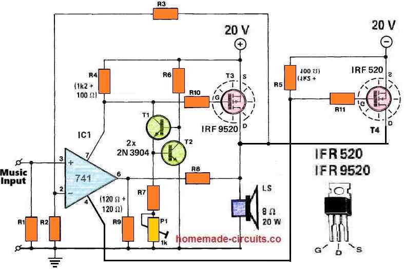
In this post we study a power amplifier design configured using an ordinary IC 741 and a couple of MOSFETs.
An operational amplifier's output power such as from an IC 741 can be typically enhanced when a complementary emitter follower transistor is coupled at its output. The same could also generally be accomplished using a MOSFET.
By Rakesh More
However, it is not necessarily a smart idea to connect MOSFETs like a complementary source follower simply because the maximum output voltage of the op amp can now be decreased substantially through the MOSFET's gate-source control voltage, which is often a few volts.
A better technique would be to hook up a couple of MOSFETs like a complementary drain follower circuit. This method has been discussed in this proposed IC 741 MOSFET power amplifier circuit article.
Circuit Description
Parts List
| Category | Component | Value/Type | Quantity |
|---|---|---|---|
| IC | IC1 | 741 Operational Amplifier | 1 |
| Transistors | T1, T2 NPN BJT | 2N3904 | 2 |
| T3 P-channel MOSFET | IRF9520 | 1 | |
| T4 N-channel MOSFET | IRF520 | 1 | |
| Resistors | R1, R2 | 100 kΩ 1/4W 1% | 2 |
| R3 | 100 kΩ 1/4W 1% | 1 | |
| R4, R5 | 1.3 kΩ (1.2 kΩ + 100 Ω) 1/4W 1% | 2 | |
| R6 | 2 kΩ 1/4W 1% | 1 | |
| R7 | 330 Ω 1/4W 1% | 1 | |
| R8 | 1 kΩ 1/4W 1% | 1 | |
| R9 | 240 Ω 1/4W 1% | 1 | |
| R10, R11 | 100 Ω 1/4W 1% | 2 | |
| Preset | P1 | 1 kΩ 1/4W 1% | 1 |
| Speaker | LS | 8 Ω, 20 W | 1 |
| Power Supply | - | ±20 V (dual polarity) | 1 |
The (switching) output current supplied by the MOSFETs is restricted by the amount of the supply voltages and the saturation voltage outputs from the transistors T3 and T4.
Resistor R8, along with R9, delivers feedback for the opamp and the MOSFETs both. The 741 op amp's open-loop amplification is, consequently, improved by (1 +R8/R9).
The closed-loop amplification of this amplifier design is defined by the value of the expression (1 +R3/R2).
The current source established by T1 and T2 is necessary for creating the quiescent current of T3 and T4 at 50 mA. The R4 and R5 should be such that, in the absence of the current source, the drop in the voltage across the resistors caused by the DC through the opamp is inadequate to switch on T3 and T4.
In the presence of the current source, and depending on how the preset P1 is adjusted, the voltages across R4 and R5 increase which in turn causes the quiescent current through T3 and T4 to increase.
With regard to the temperature dependence of the quiescent current, T2 should be installed on the common heatsink alongside the MOSFETs.
How to Adjust the Quiescent Current
Quiescent current refers to the current consumption of the amplifier during its idle state or in a situation when the volume control is reduced to the minimum level.
The quiescent current of the amplifier can be adjusted through the following points.
- Procure two 100mA 24V bulbs from market.
- Connect these bulbs in series with the +/- supply lines of the amplifier.
- Short circuit the input terminal to ground.
- Connect a speaker at the output.
- Next, switch ON power, the bulbs should illuminate brightly.
- After this, adjust the P1 preset until the bulbs just shut off or the illumination becomes almost zero.
- That's all, the quiescent current of the amplifier is not set.
- Remove the bulbs and restore the circuit to its original form.
- Now you can use the amplifier normally without the danger of over heating the MOSFETs during idle conditions.
Specifications
The output power of this 741 MOSFET power amplifier circuit is approximately 20 W into a 8 Ohm loudspeaker.
At this power specifications the total harmonic distortion of the design can be expected to be around 0.075% at 100 Hz and to 0.135 % at 10 kHz.
Questions & Answers
Схема в железе работать отказалась. И если для смещения применяются резисторы на 1,4 ком, то питание должно быть обязательно стабилизированным!
This Class A audio amplifier is capable of putting out up to 50 watts peak power, Sincerely, Clair Morrill
Swagatam, the above circuit was developed by Silliconix. in the original circuit they used a TL071 not a UA741. I bought the original application and data book in the mid 90’s. Sincerely,Clair Morrill.
Thank you Clair, I hope the readers will find this information useful. The above post was contributed by an external author so maybe he made a mistake while entering the op amp number.
Greetings Swagatam
I would like to know if You Can Ast sist with A Circuit for Prepaid KWh Meter.
I’ve been trying weather I could create it out of a timer but I ended up using A Circuit breaker to control my tenants on Yaka, very laborious and time intensive due to the need for constant Monitoring. At the same Time the dealers in those gudgets proved to very expensive and arrogant.
Agweny Richard
agwenyrichard@gmail.com
Hello Agweny, sorry, I do not have a prepaid KWh meter circuit with me at this moment.
can you do me a favor? I need a circuit for audio fix.. I need a signal tracer and signal injector… They may both be on the same circuit.
Thank you.
I have an exclusive article on signal injector, which you can find here:
https://www.homemade-circuits.com/signal-injector-circuits-for-quick-troubleshooting-of-all-audio-equipment/
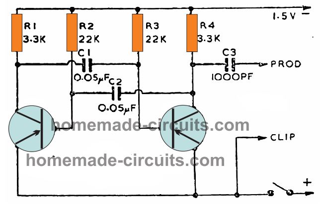
If you want an easier circuit you an try the following design:
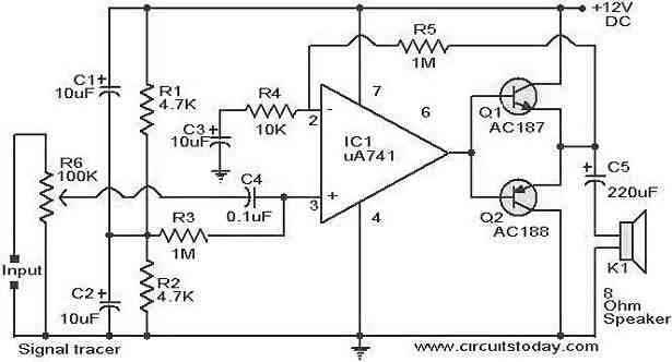
I do not have a signal tracer circuit with me, so I searched it online and found the following design:
Can you share your contact number ? I am in need of a complete, professional grade 50 – 100w RMS stereo amlifier with matching transistorised preamplifier and tone control, soft starter, speaker protection, etc. Will you please design such a hi fi project ?
With warm regards.
A.K. Mahato
Sorry, that looks quite complex, designing a professional grade stereo amplifier with all those specifications is beyond the level of my expertise.