Video Demonstration
An impressive little machine gun sound effect generator circuit is discussed here. Once built can be integrated with any audio amplifier to experience a roaring bullet studded war like simulation.
A small hobby project which can be tried by all electronic enthusiasts will generate interesting machine gun sound effect over the connected loudspeaker, quite imitating the sound effects of the many action packed computer war games.
Machine Gun Sound Effect is the Most Liked Sound Effect
We all have played TV/computer games at some period of our life and know how exciting it feels to hear the different audio effects accompanied with such games especially the ones which involve heavy arms and actions.
Boys truly love playing various action games like delta force, hitman, Command and Conquer, Sniper Elite and appreciate not only the visuals but also the produced machine gun sound effect.
Although our world has gone hi-tech and it requires just a single small chip to generate many intriguing audio sounds but building one such circuit using discrete components can be quite amusing too.
Especially the electronic enthusiasts will love making an electronic machine gun sound generator using few CMOS ICs and some other passive components.
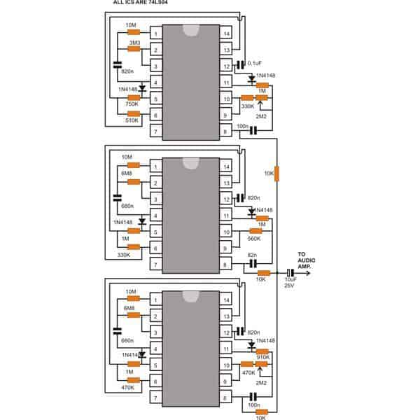
Here I have explained one simple machine gun sound effect generator circuit using three 74LS04 and just a handful of resistors. The IC 74LS04 is basically a hex NOT gate IC.
It consists of six NOT gates or inverters in one package. Each gate has two terminals one input and one output.
As the name suggests the logic generated at the output of the gates will be exactly the opposite of the received input level.
Let’s try to understand how the ICs are configured as an outstanding AK one-forty-seven like sound effect generator:
Circuit Operation
As can be seen in the enclosed circuit schematic, the unit basically consists of three almost identical IC configurations.
The pulses produced at the output of each section have their own distinct push pull ratios. These are integrated together and superimposed simulating exact machine gun shots.
Looking carefully, the circuit reveals that the six inverters from each of the IC are wired up as three astable multivibrators connected in series to each other.
The outcome quite replicates sound coming from three discrete firing posts, situated at some distance away.
The series connections of each astable are done through diodes, forcing the later to oscillate only when the previous AMV is not operating or at zero logic.
We see that two sections of the circuit include a potentiometer while the last one is without any controls. The potentiometers are used to control the frequencies of the relevant AMVs which determine the rate of gun fire sounds.
The involvement of 74LS series ensures minimum current consumption which is not more than 2 mA typically @ 5 volts.
However the generated pulses lack volume and therefore is unable to drive loudspeakers directly.
The terminated output may be suitably integrated to an audio amplifier to get the actual FEEL of the booming gun fire simulations.
The pots may be adjusted externally to reproduce and optimize the best possible machine gun sound effect.
The entire machine gun sound effect circuit can be assembled over a piece of general PCB and fitted inside the audio amplifier cabinet. The circuit may be powered from the amplifiers power supply itself.
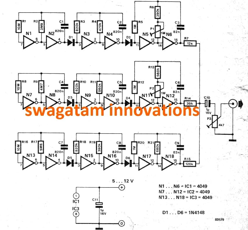
The Original Design from Elektor Electronics
Parts List
- Resistors are 1/4 watt 5%
- 10 M = 3
- 5.6 M, 4.7 M, 3.9 M, 120 k, 39 k, 470 k, 680 k = 1 each
- 820 k = 3
- 560 k =2
- 390 k = 2
- 1 M = 3
- Preset 1 M = 2
- Preset 4.7 k = 1
- Capacitors
- PPC 820 nF = 6
- PPC 82 nF = 3
- Electrolytic 1 µF, 16 V = 2
- Diodes 1N4148 = 6
- IC 4049 = 3
Interesting Feedback from Mr. Henry Bowman
Swag, I’ve been analyzing the three stages of the 4049 schematic and it’s much simpler than I first realized.
The only sections that provide the actual fire is the last two inverters in each chip. I can utilize one chip to make the machine gun sound.
Using two sets of two inverters each, and making two identical output sounds and delaying one just a few microseconds should make it sound realistic. I don’t want to hear three different machine gun sounds as it is currently designed. I’m still using the 4069 chips, which have the same pin configuration as the 74LS04.
See the description below:
CD 4049 machine gun sound operation: On the schematic, In 4049 IC#1, N1 and N2 gates provide the first oscillator section.
Output timing is due to values of R1, R2 and C1. The output at pin 4 is high for about 3 seconds, then goes low for about 4 seconds. When the output goes low it triggers the next oscillator (N3 & N4) to began oscillation.
Pin 10 on N4 goes low four times during the time that pin 4 on N2 is low. Each time N2's pin 10 goes low, it triggers the actual machine gun fire that is developed by N5, N6, R5, R6, P1 and C3. N6 pin 15 provides the pulsed output to simulate fire. P1 adjusts the rate of output (fire) pulses.
The second chip has the same principal as the first one, but some resistance changes which allow longer timing intervals between gun fire bursts .
The same applies to the third chip, with output bursts different from Chip 1 & 2. The rate of output pulses on Chip 3 pin 15 is fixed and non-adjustable.
Pin 15 on each of the three chip's output have different size resistors, ie, 12K, 39K and 120K. Each pin 15’s output will have different levels of pulses.
When powered up and connected to an amplifier, it gives the sound effects that there are three machine guns firing, one after the other, from near and distant locations.
More Updates from Mr. Henry:
The following email information was sent to me by Mr. Henry Bowman regarding the improvements he made in the above design, allowing the circuit to become better, smaller and simpler. Here's a technical description and the schematic of the modifications:
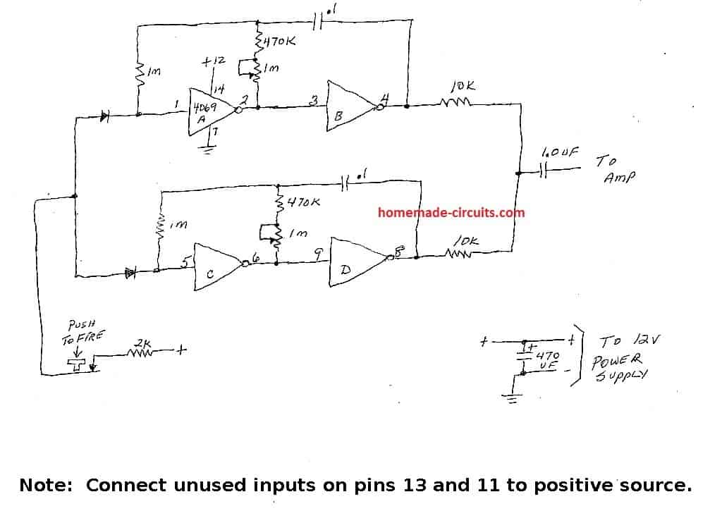
"I eliminated two of the chips and only used one 4069. The 4069 is a 14 pin chip, so it’s different than your schematic of the 4049. I’ve attached a scribbled schematic to show my modification.
The first oscillator is inverters A & B and the second oscillator is inverters C & D.The inputs of both oscillators are held high by the normally closed push button contacts through a 2K resistor and the two diodes.
Once the push button is pressed, the positive potential is removed and both oscillators start pulsing.
Both oscillators should be adjusted as close as possible to the same pulse rate, using a logic probe or oscilloscope.
When connected to a amp and speaker, tweak one of the 1 meg potentiometers to create a slight delay for a more realistic sound.
Shielded cable should be used from the circuit board to the amp input to reduce hum."
Henry
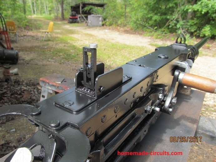
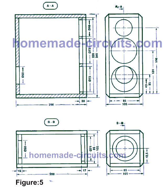
The Machine Gun Model
The following image shows the machine gun model which was fabricated by Mr. Henry in his workshop and used for housing the above machine gun circuit.
The entire set up ended up looking so realistic that folks around had to first confirm from Mr. Henry whether it was really safe to stand in front of this device 🙂
More Details from Mr. Henry:
"I put it in a metal box today and installed a female mono phone jack. in the rear I have a shielded cord with a rca plug going to the amp and a mono male plug (tip-sleeve) to plug in the rear of my box. No hum anymore.
This photo is the reason I have spent so much time on the gun sound ! This is a replica that I built last fall. Everyone that sees it thinks it’s the real machine gun. I’ve got 25 fifty caliber inert shells with links to add to the realism."
Henry
The following video clip shows the Test Result of the above simplified machine gun sound generator circuit through an amplifier (Courtesy: Mr Henry Bowman)
Kindly bear the background Hum sound picked up the amplifier 🙂
Enhanced Machine Gun (MG) Sound Generator Circuit using IC SN76477
By: Mr. Henry Bowman
This sound generator chip can generate bird chirps, freight train, race track engine, siren, phasor gun, organ (with more push buttons), jungle sounds, wind sounds, etc.
It contains three oscillators being SLF (super low frequency), VCO (voltage controlled oscillator) and noise oscillator. You can select any combination of these three.
The sound decay function added a lot of realism to the gun shot sound. I found an old data sheet (attached) that shows someof the sound applications.
I plan on adding more rotary switches with selectable capacitors to make more sounds.
Buyers need to be aware that there are two sizes of this chip. The SN76477 is the standard large size and the SN76477NF is the smaller size. The NF size socket would be very difficult to use without a printed circuit board, or an adapter.
I finally received two of the larger SN76477 sound chips and very pleased with the results. I looked all over the Internet to see if anyone had made a mg sound with this chip and no luck.
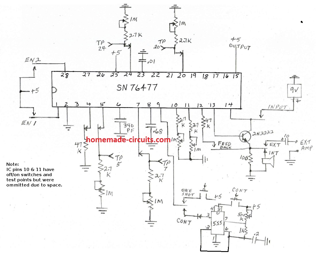
What I finally wound up doing was to add a 555 timerchip and placed it’s pulsed output on to the one shot pin 9.
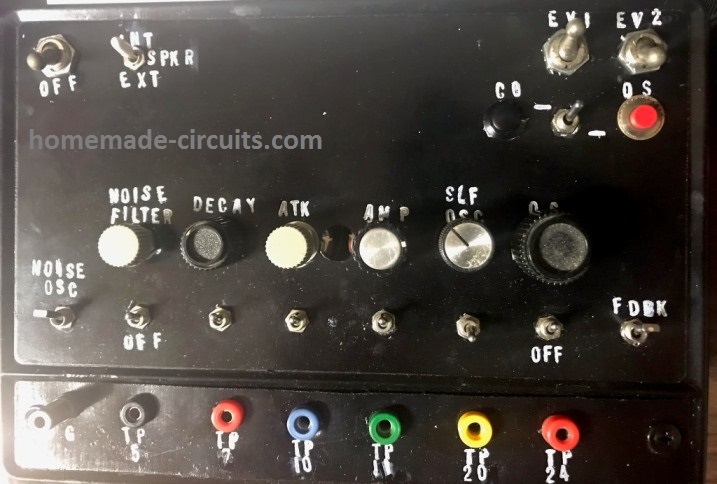
I added a spdt switch to select the one shot sound or the constant mg sound. I’m using push buttons for both sound types. I’m powering the SN76477 with a 9 volt battery.
This chip has a regulated 5 volt output, so I’m using that voltage to power the 555 IC. The test points enable me to turn off the connection to the ic pins and use a ohm-meter between each test point and“G” or ground. I can set each potentiometer to the desired resistance.
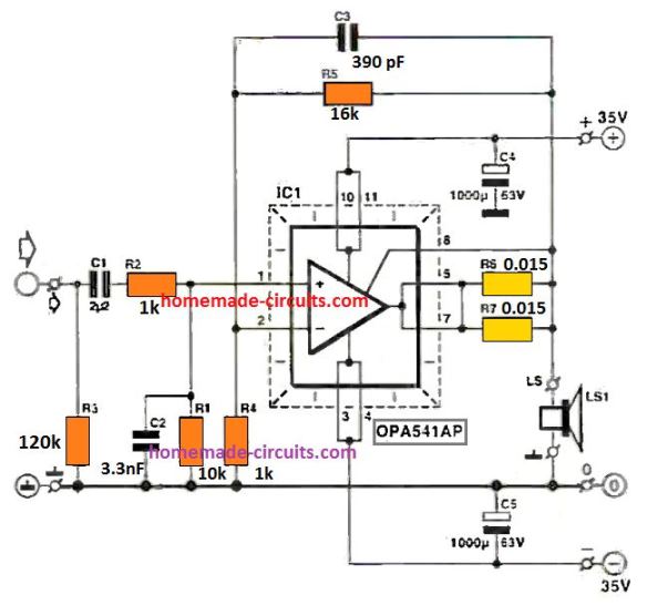
I also added a jack to connect to my 200 watt amp. I haven’t tried that yet. I tried to send you a longer video explaining each function, but my Iphone said the video was too large, so I really had to condense it. I’m working on the revised schematic and will send it soon.
This is the revised schematic of the experimenter’s board, correcting the error on pin 9. A positive pulse can be appliedto pin 9 for one-shot sounds, but operating a switch in parallel to the push button to +5 would inhibit all sounds.I corrected the drawing showing a spdt switch on pin 9 to correct the problem.
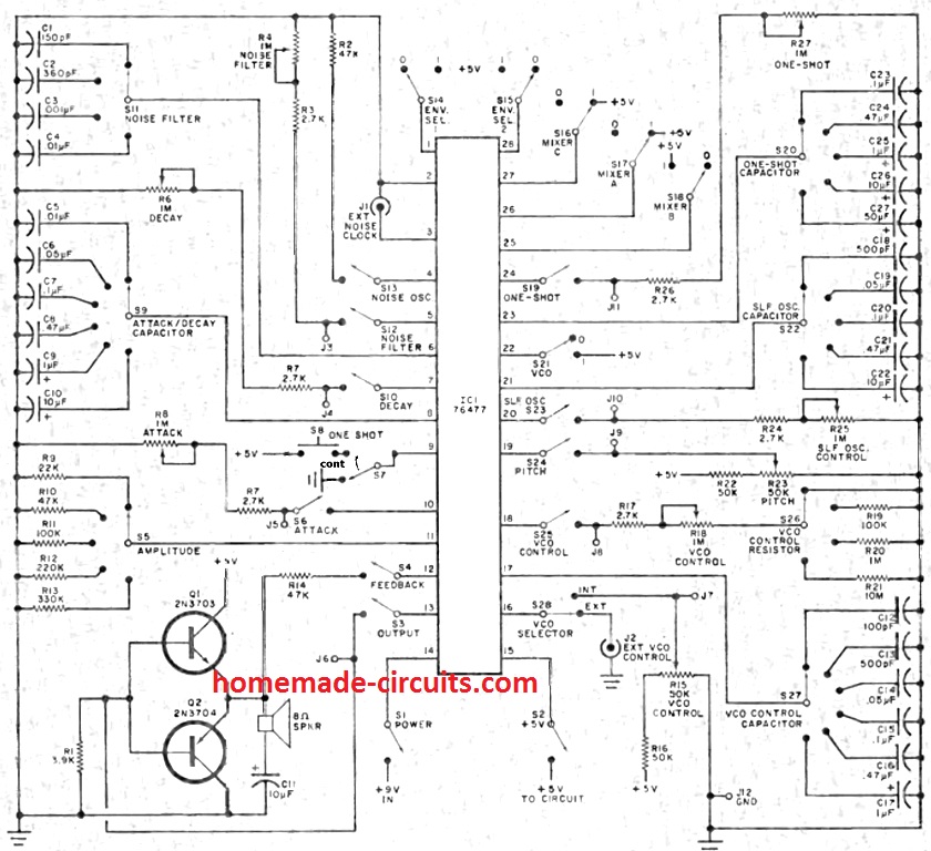
I will eventually add rotary switches to select various capacitors and be able to create more sounds. Also need to add three spst switches on pins 25,26 and 27 to combine the sound oscillators.


Questions & Answers
I would like to talk to you about building a machine gum circuit that I can install in my kit AirPlane with a button on the yoke. Would you be interested in helping me with that? And if so, how do I get in touch with you.
Hi, the above circuit is fully tested so you can go ahead and build this circuit for getting the intended results.
You can contact a good PCB designer and tell him to design a proper PCB for this and then you can assemble the parts on that PCB…
Thank you for your reply. I have tried now for three months to find someone locally to help me build your circuit. I finally found a group in India that say they can do it, but it has been impossible to communicate with them. I would sure appreciate any help you could give me to find a PCB builder. If you would have time to talk I could explain better my plan for this circuit. I really like your pcb’s sound and I have a very cool application for it. I am happy to pay for any time you help if that’s something you would like.
I’m not sure how this “reply” works but if you have my email could you please reply there and we could exchange phone numbers.
Thank you Jon, and I understand your problem, however it can be difficult for me to find a PCB designer for you, since I not in this business since long and out of touch with these guys.
I would suggest you to search someone online, there are so many websites who provide PCB making services at reasonable costs.
You should be able to find Indian as well as Chinese PCB manufactures and vendors who would readily provide their support to make this PCB available to you.
I saw your email also, however since I prefer answering to my blog comments, so I am answering your comment here, which you posted under this machine gun simulator article…
I was looking for the 555 timer based machine gun sound effect, but while looking on the web I discovered that the website next.gr had copied your webpage to their site entirely without giving you any credit at all!
Thank you for your kind information, I appreciate it…I will investigate the issue soon…
Hello, in the end of -70 I built an RC model of a Swedish Destroyer and I wanted to complete it with loud of mashinegun and 12cm artillery. So in 1983 I found the IC 76477 to make these louds. The circuit board is a little similar to your board.
I have now started to make it ready, but some problem with the Ic. I have now ordered some new from China.
can I send some photos for you?
Best Regards
Eve
Sure, once you finish the project you can send the pics to me. You can send it to: contact @ homemade-circuits.com
Thanks for quick reply. I will send some pics later today.
Eve
Thank you very much for the pics. I saw them all and they all looked so interesting. Please keep up the good work.
OK, no problem…
Hello Guys is someone of you able to help me. I have tried to recreat the handdrawing but nothing is happening
The TTL version of the 74LS04 will not work for this circuit because it requires resistor values below 1 Killiohm to oscillate, but the CMOS verson (74C04, 74HC04, 74HCT04) of the 7400 will work in this circuit
Dear Mr.Bowman,
I wish to construct your Enhanced Machine Gun Sound Generator Circuit
using IC SN76477 at frequency of 15 to 25 KHz to drive away monkeys
without disturbing the neighborhood.
Could you please let me know the component values to achieve this.
Awaiting a favorable reply.
Best Regards,
Ronald Fonseka,
SRI LANKA
Hi Roland,
you can try the 3rd circuit from top, and reduce one of the 0.1uF capacitor value which determines the frequency of the sound, until the sound reaches 12kHz, and when the sound is almost inaudible.
You will have find which out of the two capacitors determines the frequency, and which one determines the firing rate.
Decrease the capacitor which is responsible for the frequency generation.
Swag, The 4049 ic’s need 16 pin ic sockets instead of 14 pin, so it’s going to take several days to get
this project rewired. I’ve only found one 4049 and may have to order two more.
It will be worth the effort if it produces a realistic sound.
Henry
Hi Henry, you can try the circuit on a breadboard, so that won’t require IC sockets…breadboard will be much convenient and allow you to use the same parts repeatedly for many future experiments…
Hi Swag, I could only find one 4049 ic and I didn’t want to take the time involved to bread board this beast. I found three CD4069 inverters that had the same 14 pin configuration as the 74LS04 ics.
I installed them and they work ! They can take up to 15 vdc, so I removed the 5v regulator and
using 12 vdc. Connecting it to an amplifier, it fires three shorts bursts then pauses for about
1/1/2 seconds then fires another three bursts and continually repeats. It’s getting close to a
realistic gun sound. I’ve got to change the output resistors to match those on your 4049 schematic and also some caps and other resistors. This will probably enhance the sound and change the timing interval. This had made my day ! Can’t thank you enough for finding and posting the 4049 schematic !
Have a Merry Christmas and Happy New Year Swag !!
Henry
That’s great news Henry, I am glad it finally worked for you.
Thanks for trying my circuits! If you have any more doubts please let me know, I’ll be most happy to help!
Wish you too a Merry Christmas, a Very Happy New Year and a great weekend
Swag, I’ve been trying different speakers and it works best with a large stereo type speaker that includes a tweeter and crossover network. The speaker is connected to a VR3 200 watt 12v car amplifier. If I put it outside the house, the neighbors would think a war was going on !
I have a replica Browning 50 cal. M2HB and plan on putting all the electronics in a wooden ammo
box. Adding a super bright led in the front barrel hole and synchronized with the 4069 pulses
would provide a realistic effect at night !
That’s amazing Henry, if it is possible please send a small video clip to my email (homemadecircuits @ gmail.com)… please do it only if it is convenient for you, otherwise please do not bother…. I am indeed enjoying your work more than you 🙂
I have spent several days building, checking and rechecking this project. None of the inverter stages are producing output pulses. The resistance used in the first oscillator stages in each chip seem extremely
high values. 10 million ohms in series with 3.3 million ohms in chip 1’s first oscillator stage. Should that have possibly been labeled 10K in series with 3.3K ? Another question is on pin 12 of the first IC. Why is the capacitor connected to pin 12 labeled 0.1 UF ? All the other 0.1 uf caps are correctly labeled as 100nf. Should the cap on the first chip’s pin 12 actually be 1.0 uf ? My chips test good in other applications, so there must be some serious errors in the above schematic. I use a Radio Shack digital logic probe to test outputs. Any help would be appreciated.
I have updated the original design at the end of the post, please verify for any mistakes I might have done while interpreting it…
Thanks very much Swag, I see some differences in resistors and the chips are 4049 inverters
instead of 74LS04. Hope I have some of the 4049’s. It will take a while to modify my circuit.
The 4049 chips can use 12v instead of the 5v required for the 74LS04’s.
I will let you know how it works out.
Thanks again !
Henry
You are welcome Henry, yes 4049 will allow 12V operation, I wish you all the best with the circuit
I had taken this circuit from a very old Elektor Electronics magazine, I’ll try to find the book and the page, if it is still there with me I’ll try to post the actual schematic soon here for your reference…