Bigger speaker boxes produce proportionately higher bass effect, this fact is know to all of us. However, bigger boxes are not only expensive, they can be cumbersome and bulky.
How about having the very same high bass effect, that a bigger box would provide, from a much smaller and compact speaker enclosure? Sounds strange right?
In this post I have explained exactly how high quality music with extended bass effects could be achieved using relatively smaller speaker enclosures. Along with the compact high bass enclosure, the crossover network circuit discussed here, enables the sound quality to be outstandingly clear and rich!
Introduction
A perfect loudspeaker system would respond like a smooth piston, irrespective of the audio frequency. Such a speaker could be simply nonexistent. Real speakers employ a cone with a material that oscillates complying with the surrounding atmospheric properties, to generate a basic resonance.
Beneath this resonance point, the effect crumbles apart quickly, while over this resonance point the smooth piston like functioning continues only within a limited spectrum of frequencies and then the effect begins to deviate and drop yet again.

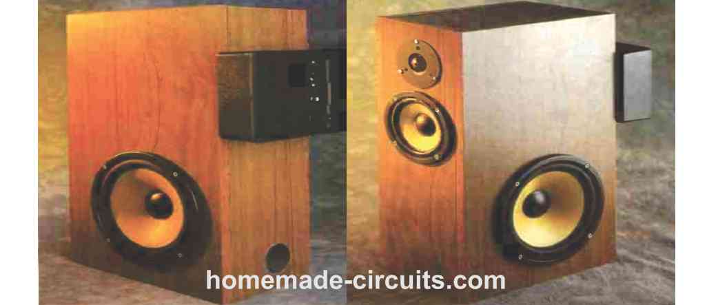
Design Parameters for the Enclosure
When we have audio frequencies where the speaker's diameter happens to be smaller than a wavelength of the audio vibrations, antiphase waves from the backside of the speaker cone scatter all over it to terminate the desired audio effect in the front side.
This is exactly why the speaker demands an appropriate box to be fitted in. The easiest approach is to install the speaker inside a sealed box.
However, in a sealed speaker box, the surrounded air offers rigidity that adds up with the speaker cones resistance and causes the resonant frequency to rise, resulting in unfavorable conditions which becomes difficult to eliminate.
To achieve a prolonged high bass effect response it becomes necessary to go for a much bigger or a gigantic enclosure. A choice could be to employ a loudspeaker which has a reduced free air resonant frequency, but has an efficiency proportional to the cube of that frequency.
Another way is, to use a reflex enclosure, which consists of a duct cut into the top front of the enclosure. The air volume through the duct passage and the acquiescence of the air within the box work like a kinetic tuned circuit, energized with the speaker cone's backside frequency impact.
Duct output functions in an out-of-phase manner with respect to the rear speaker cone sound emission, and oscillates in phase producing the desired high bass effect from the speaker front side.
For this reason, within a limited range of frequencies, the duct or vent method can be implemented for enhancing the bass output through the speaker.
Below the resonance level of the speaker enclosure, the sound wave radiation through the duct becomes out of phase with the speaker, and as a result the desired high bass production drops a lot quicker compared to that in a sealed enclosure.
Therefore response of such a systems gets unimpressive. However, one good thing is, although, the speaker's resonant frequency is negligibly improved compared to its open air value, the distortion level happens to be quite low.
An additional benefit of reflex type speaker box is that the speaker cone excursion for a given output is tremendously minimized at and around the speaker enclosure resonance. The reason being the loudspeaker is able to "see" the excessive physical impedance of the enclosure's resonant circuit.
Reflex Speaker Box
As a result of the landmark efforts by Theilel, and Small, it is a straightforward job to create a superb reflex speaker system, despite the fact that layout is restricted by the electrical specs of the bass devices obtainable.
No matter what, a significantly large low frequency response can be normally only achieved by employing a large size speaker enclosure. This situation confirms that almost all commercial speaker systems with a reasonable dimension demonstrate show an inclination to possess minimal usable output under 60 Hz, thus the loss of practically two octaves of the acoustic frequency spectrum. What can be the solution to this problem?
There exists a common perception that genuine bass cannot be produced in small speaker boxes. Nevertheless, as my very own next door neighbors will testify, this may not be true. It is merely that this sort of efficiency can be unattainable using the techniques previously discussed.
However, a number of remedies are already developed, the most widely known perhaps being vibrational feedback, where a tiny transducer is mounted on the speaker cone and the resulting transmission channeled back into the amplifier's feedback loop. This is applied both to fix the low frequency roll-off and also to minimize harmonic distortion.
An additional approach, included in this design, is the 6th-order reflex speaker system where the low-frequency response is expanded through an under-damped high-pass filter, typically by means of an op amp circuit positioned between preamplifier and power amps.
As outlined by Keele, the effect could be prolonged by 1/2 an octave in return to a 3 dB less maximum drive signal. Some other versions on the concept are available, such as, sub-resonant speaker devices founded by Linkwitz and Harcourt.
What Restricts the Bass
The factor that actually restricts the sustained bass effect of a driver unit, is the air mass that can be moved. This air mass is a directly dependent on the speaker cone area and the peak frequency limits of the speaker cone.
As long as the speaker unit could be controlled for a flat response, the enclosure proportions could be maintained very compact without impacting the general bass response.
Because the response waveforms for both sealed and reflex speaker boxes can now be precisely worked out, it becomes possible for us now to enhance the low-frequency limit of smaller speaker systems.
The simple idea is, to employ filter circuits to create a flat response for the systems, which is both uncomplicated and cheap.
Choosing Drivers Units
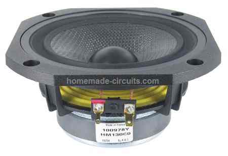
From the extensive range of available drivers for our proposed small box high bass system, I decided to go with Audax units because of their reliable Theile/Small parameters.
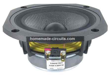
The HT210F0 bass and HT130F0 were intended to be employed collectively, which us substantiated by their meticulously matched up reference efficiencies. These may also be available in pairs, computer matched to within <0.3dB, to ensure that gain matching can be avoided.
Developing a good speaker system can eliminate the several, usually mutually interconnected issues for getting an impressive bass effect with smaller speaker boxes.
At best, the specific responses of the cross over drivers employed in this circuit work exactly like the asymmetrical band-pass filters, using unnecessary resonances chucked in.
These types of effects requires to be altered and tamed in order that the system response is similar to a band-pass filter having a toned output throughout the acoustic frequency range.
One of the many approaches employed was an easy treble response and precise incorporation of driver responses. After working with a number of tweeters units, such as titanium and hard-dome types, I decided to go with the Morel MDT29, a soft-dome unit having a fantastic, sleek and resonance-free effect coupled with a likewise soft low-frequency roll-off.
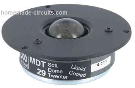
Additionally, it is a sturdy ferro fluid-cooled device competent to handle high power transients. It is currently clearly recognized that a wide stereo visuals demands decent horizontal audio distribution.
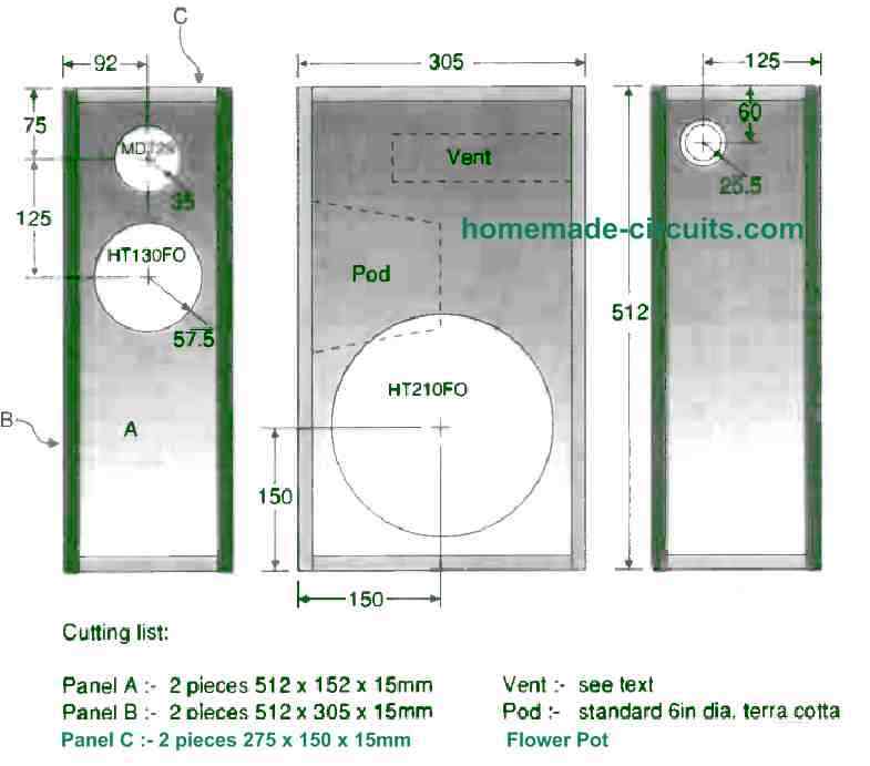
This calls for a narrow speaker box, and to achieve the smallest front side baffle measurements, the bass driver is clamped on the edge of the speaker box. This actually does not trigger any complications, since below 100 Hz frequency, the response from the bass driver is over a single direction.
The mid-range driver requires its very own housing. In a three-way crossover models, it is a widespread approach to attach this sub-enclosure inside the primary speaker box and, after many hours of deep thinking, I selected a garden 6in diameter terracotta flower pot.
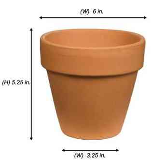
Despite the fact that the preference may look unusual, the non-parallel design means that, around the mid driver's range, vertical sound waves are not able to happen inside the sub-enclosure.
Fitted in this manner, the HT130FO's bass resonance is increased from 48 Hz to 144 Hz, through a accompanying rise in Q from 0.25 to roughly 0.73, the healthy selection for the crossover point across the mid-range and bass drivers.
Enabling the roll-off for the bass unit with this frequency additionally means that the speaker box is acoustically compact and much smaller. In other words, the wavelengths of the audio supplied through the driver are much much longer compared to biggest speaker box available. Consequently, standing waves can't be created inside it.
Circuit Description
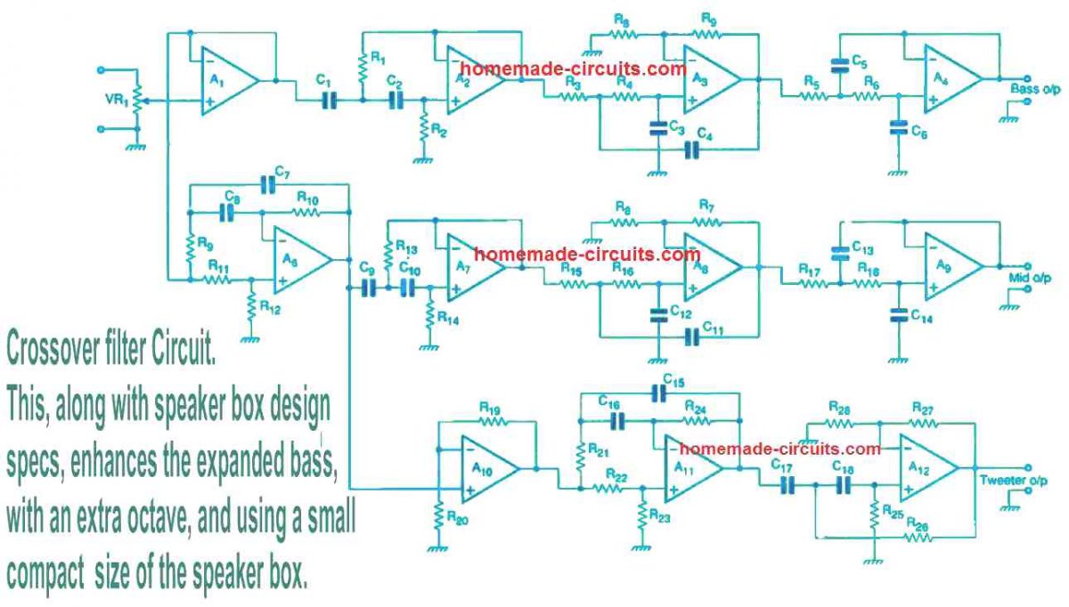
The line-level inputs are put on the volume control VR1 and subsequently on the buffer amplifier constructed using A1. After this the audio frequency is bifurcated across three sections. Amplifier A2 is set up like a high-pass filter which has a turnover frequency of 28 Hz and a Q of 2.82, principally to deliver bass equalization for the woofer.
Bass frequency loading is done at the 6th order and the bass speaker box is tuned with a low frequency of 35 Hz. This low frequency generates an overdamped 4th order filter effect. Low frequency boost implemented through op amp A2 flattens the response, guaranteeing a -3dB point for the speaker system at 32 Hz.
Reflex type speaker units are generally not loaded acoustically at subsonic frequencies and, while in traditional speaker systems, the driver excursion is sacrificed through subsonic interference. A well-defined filter roll-off makes certain that subsonic frequencies are adequately attenuated in order to prevent overloading. Initiatives to force the effect lower than this frequency level causes excursion limit complications.
Crossovers between the bass and mid-range drivers stages is taken care of by op amps A3 and A4, which work like a 4th-order, low-pass filter using a couple of 2nd-order sections. Q of the final filter can be 0.5, the situation of crucial damping merging the most effective transient response along with fast stop-band attenuation.
Properties of the mid-range enclosure determine the selection of crossover point. The midrange driver, rolls off at the bass frequency last limit at 144Hz, generating a very similar effect like a 2nd-order filter having a turnover frequency of 144 Hz and a Q of 0.73.
By itself, the high Q of this resonance might produce an adverse peak slightly over the resonant frequency. To keep the response under control the drive signal is subjected to a high-pass filter through the op amp A7, that provides an identical turnover frequency although with a Q of 0.68. The audio effect generated due to this is equivalent to the intended 4th-order high-pass crossover response.
Due to the fact the driver's audible zones are located in distinctive planes, time delay utilizing all-pass filters is necessary for the compensations. (This noticeable contradiction in conditions is enforced to circuits that offer a flat frequency response although a predetermined time delay.)
A couple of these filters are employed in the circuit. The 1st, constructed using the op amp A6 offsets the time delay between the woofer and mid-range units. This is similar to, a -24° phase shift at 144 Hz. The 2nd offsets the time delay between mid range and tweeter. Here a -50 mm offset is adjusted by op amp A11 and the involved circuitry.
Active crossover
In a standard passive type crossover filter system, we are able to adjust the Q of the system by changing the ratios of the reactive elements, taking into consideration the-hopefully-resistive load introduced through the speaker.
In real world , this can be very challenging to accomplish owing to reactive influences in the drivers. On the flip side, active crossovers can be quickly created without depending on inductors and are not affected by the driver loading.
Despite the fact that many feasible filter designs can be found, the best option for active crossovers are often the Sallen and Key types, especially the 'equal-component' and 'unity-gain' versions, displayed in Fig below.
Common op amps are employed for the active components and many other types can be tried; such as the TL0 series, employed in this particular design, are effectively proven and encouraged for prototype work.
In the unity-gain circuit, the op amp is configured like a buffer.
Calculating the High-Pass Filter
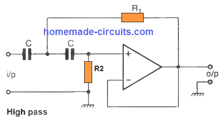
Part values for the high-pass system could be calculated through the below given equations.
R2 = a/(1.257 x 10-6foC), select a value for the C that is suitable to you.
R1 = 1 / (3.142 x 10⁻⁶afoC), where a = 1/Q, and C is expressed in microfrarads (uF)
Calculating the Low-Pass Filter
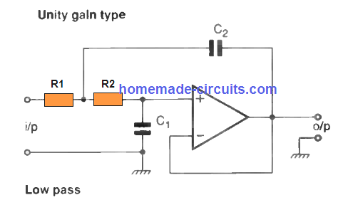
Select the value for R that is most convenient for you, then:
C1 = a/(12.57foR)
C2 = 1/(3.142afoR)
fo is the intended cut-off transition frequency
The Q of the filter is established through the voltage gain of the circuit, which is fixed through the ratio of R3 and R4.
R3 needs to be (3-(1/Q+1))R4. Higher order filters can be attained by cascading 2nd-order filters; the Q of a cascaded pair can be equal to the product of the Qs of each segment. The following graph demonstrates the result of Q over the response curve of a 2nd-order filter, which is a high-pass type here.
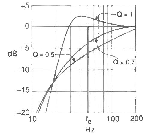
The effect of low-pass filters can be a preciely identical image. Underdamped filters of Q>0.7 indicate a peak in the passband, while this cannot be seen in overdamped filters having Q<0.7.
Filters with a Q of 0.7 are Butterworth types, that enjoy the flattest passband response along with zero peak. Nevertheless, it could be proven that most effective transient response can be acquired with a Q of 0.5, irrespective of filter order; therefore this value has been the most popular Q of crossovers.
The regular Linkwitz/Riley crossover works with a 4th-order filter for both high and low-pass segments. An additional good thing about the 4th-order filter is usually that the phase difference between the sections is minimal.
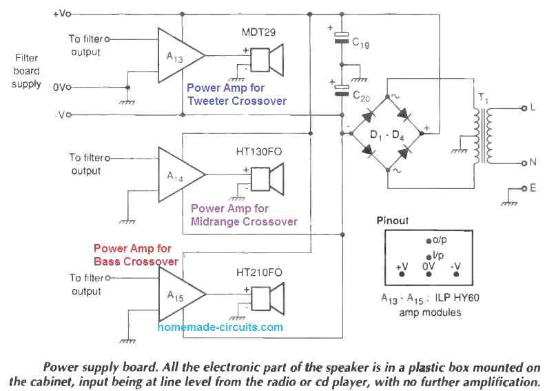
Power Supply and Power Amp Configuration for the Crossover Circuit
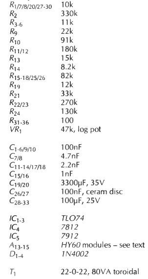
Parts List
Final Results
You may be still wondering, is the above effort really worth it? The answer is yes Certainly. The stereo resolution of this active crossover network design is exceptional and the elimination of the standing waves enhances the intricate performance of the speaker box.
By causing the specified driver units to extensively work in their piston regions, along with the distinct roll-offs of the crossovers, add to smooth driver implementation. The extra bass octave supplied, enables audio to be reproduced through precise weight and authority.
In a nutshell, I personally have listened to the speaker output performance for pretty much a year at this moment and have had no desire to replace these small speaker with big bass for any other modern variant, no matter what the price may be.
I have read your article carefully. Maybe it’s my fault that I don’t understand English well but the bass speaker has to be locked in the jar?
yes that’s right but not the bass speaker…..it is the backside of the mid-range speaker which must be covered with the terracota pot.