A simple high voltage generator circuit is explained here which can be used to step up any DC level to about 20 times or depending upon the transformer secondary rating.
Circuit Operation
As can be visualized in the shown high voltage arc generator circuit diagram, it employs a standard transistor blocking oscillator configuration for generating the required stepped up voltage across the output winding of the transformer.
The circuit may be understood as follows:
The transistor conducts and drives the associated winding of the transformer via its collector/emitter the moment power is applied to the center of the transformer.
Circuit Diagram
The upper half of the transformer winding simply provides a feedback to the base of the transistor via C2 such the T1 stays locked on to the conduction mode until C2 charges fully, breaking the latch and forcing the transistor to begin the conduction cycle afresh.
R1 which is a 1K resistor is positioned to limit the base drive for T1 to safe limits while VR1 which is a 22k preset may be adjusted for obtaining an efficiently pulsating T1 frequency.
C2 may be also fine tuned by trying other values until the highest possible output is attained at the trafo output
The transformer could be any iron-cored step down transformer (500mA) normally used in transformer type AC/DC adapter units.
The output right across the transformer output would be at the rated secondary level, for example if it is a 220V secondary, then the output could be expected to be at this level.
The above level could be further amplified or stepped up through the attached diode, capacitor charge pump network akin to cockroft-walton generator network.
The network raises the 220V level to many hundreds of volts which may be forced to spark across an appropriately positioned end terminals of the charge pump circuit.
The circuit can be also used in mosquito swatter bat application by replacing the iron cored transformer with a ferrite core counterpart.
High Power 10 kv Generator Circuit
If powered with a 30 V power input, the circuit detailed below can provide a high voltage which range from 0 to 3 kV (type 2 an even provide from 0----10 kV. NAND gates N1----N3 are wired like an astable multivibrator (AMV), which powers the darlington transistors T1/T2 with a 20kHz souarewave frequency.
Because of the reduced current circulation (decided by R4 via the transistors, they are not able to get saturated, leading to a quick switch-off. The incredibly rapid switching of the transistors generates a pulsating signal of around 300 V across the primary winding of Tr1.
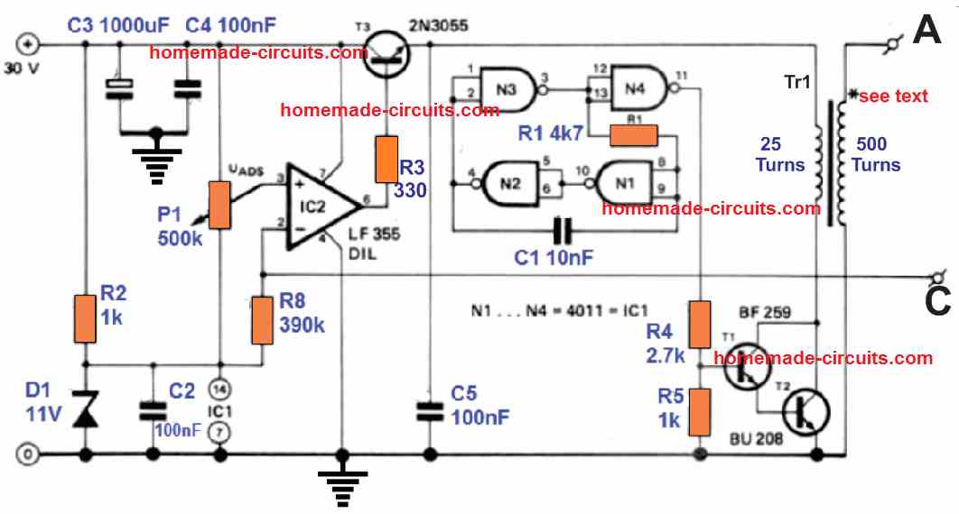
This voltage is subsequently boosted and stepped-up proportionately as per the turn ratio of the secondary windings. The 1st variation (type 1) of the circuit employs half-wave rectification. Version 2 is actually a cascade rectifier salvaged from an old T.V. set.
Variation 2 provides a voltage 3 times greater than version 1 since the cascade rectifier functions like voltage multiplier (3X). IC2 controls the output voltage.
The opamp compares the voltage created across the P1 preset with the voltage existing at the voltage dividers R6/R8 or R7/R8 junction.
In the event the output goes higher than the preset voltage level, IC2 may cut down the supply voltage towards the output by using T3.
The main section of the circuit is the transformer. Eventhough it is pretty vital, its design isn't that critical.
A range of E, EI ferrite cores with a diameter of 30 mm might work extremely well pretty effortlessly.
The core must not include any kind of air gap, an AL value of 2000 nH will be just appropriate.
The primary winding includes 25 turns of 0.7 mm 1 mm super enamelled copper wire and the secondary is built using 500 turns of 0.2 … 0.3 mm super enameled copper wire.
The primary and secondary windings needs to be effectively insulated from one another!
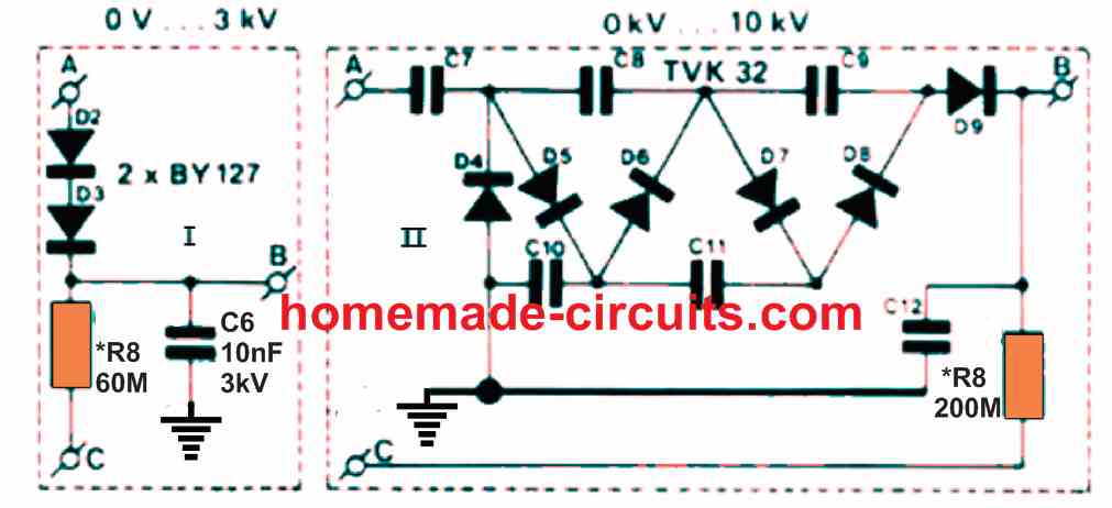
Dependent upon the high voltages, the user must be careful about the following points:
Capacitor C6 should have the ability to handle a minimum of 3 kV. R6 in version 1 includes six 10 M resistors connected in series. R7 is a 10 M resistor, built by using 10nos of 1M in series.
This is implemented to counteract spikes from the output. Both circuit takes in around 50 mA with no load attached, and 350 mA while ensuring 2 … 3 W to a load.
Transistors T2 and T3 may demand heatsinks.
9V to 300V Generator Circuit
The use of voltage multipliers to generate larger output voltages is typically less expensive only when the desired voltages are lower than 6 times the supply voltage.
Other circuit configurations are advised when hugely large step-up ratios are necessary (e.g., hundreds of volts supplied through a 12-volt supply).
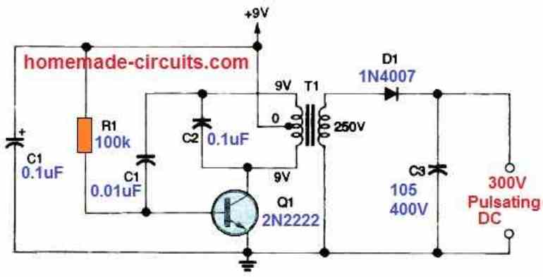
As shown in the above diagram, the output of a cheap low-voltage oscillator or square wave generator may generally be used as the input of an appropriate step-up voltage transformer (an ordinary step-down transformer connected in reverse).
The transformer's secondary winding produces the desired high AC/DC output voltages.
With a simple DC-to-AC converter, this AC power could be quickly converted back to DC. A DC-to-DC converter circuit as depicted above is able to create a 300-volt DC output out of a 9-volt Dc power supply.
The Hartley inductive-capacitive (LC) oscillator is formed by transistor Q1 and its accompanying electronics in this design. The primary winding voltage, which varies from zero and nine volts, is fed to the 250-volt transformer T1.
The inductive component in the LC oscillator is the main inductance, that is adjusted through capacitor C2. At the secondary of T1, the voltage level is boosted up to roughly 350 volts peak.
Diode D1 half-wave rectifies this output, which charges capacitor C3. The capacitor has the potential to deliver a strong yet non-lethal electrical shock with minimum loading on C3.
With a load current of a few milliamperes, the output decreases to around 300 volts when a permanent load is connected.
High Voltage Generator Using a Single IC 555
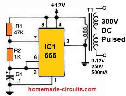
A simple low power high voltage generator can be built using the IC 555 and a step down 0-12V transformer.
The IC 555 is wired as a high frequency oscillator which switches the 0-12V side of the transformer with a 12V/200mA supply.
This induces an equivalent high voltage pulsating DC on the other side of the transformer to generate around 300 V pulsating DC at the output.
Using Ignition Coil
The next circuit we'll look at is a solid-state negative ion generator. This circuit, depicted in Fig. 6, is pretty much the easiest to design and use.
A low-frequency pulse is generated by a 555 timer IC, which drives the gate of Q1, a power HEXFET. In turn, the IRF511 transmits a high-current pulse into the primary of the automotive ignition coil T1.
The secondary winding generates many thousand volts, which are rectified by diode string D1—-D35 and used to charge C3.
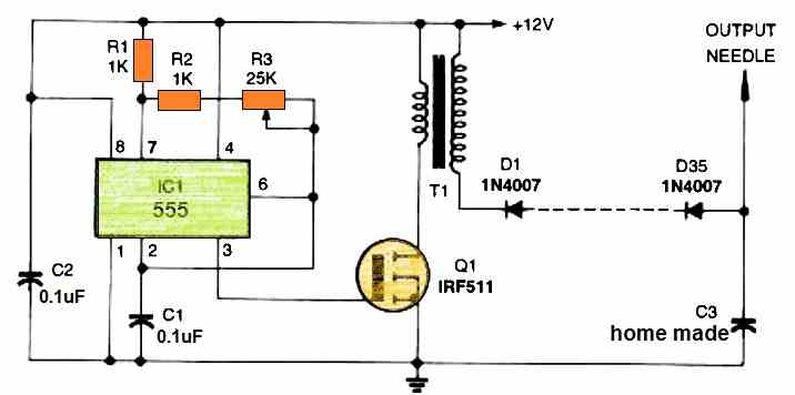
One or more sharp needles blasts the ions into air. C3 can be created at home or obtained from market.
Set the frequency of IC 1 with potentiometer R3 to the maximum output voltage with the minimum input current.
To get the highest output and circuit efficiency, you can tinker about with R3.
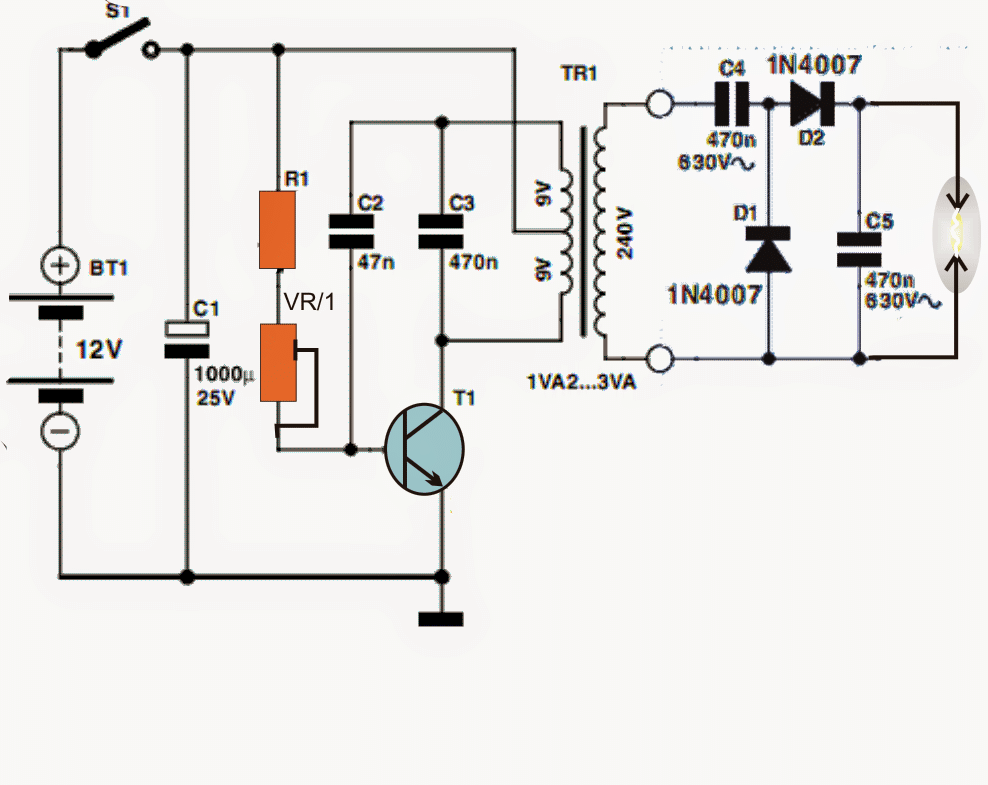
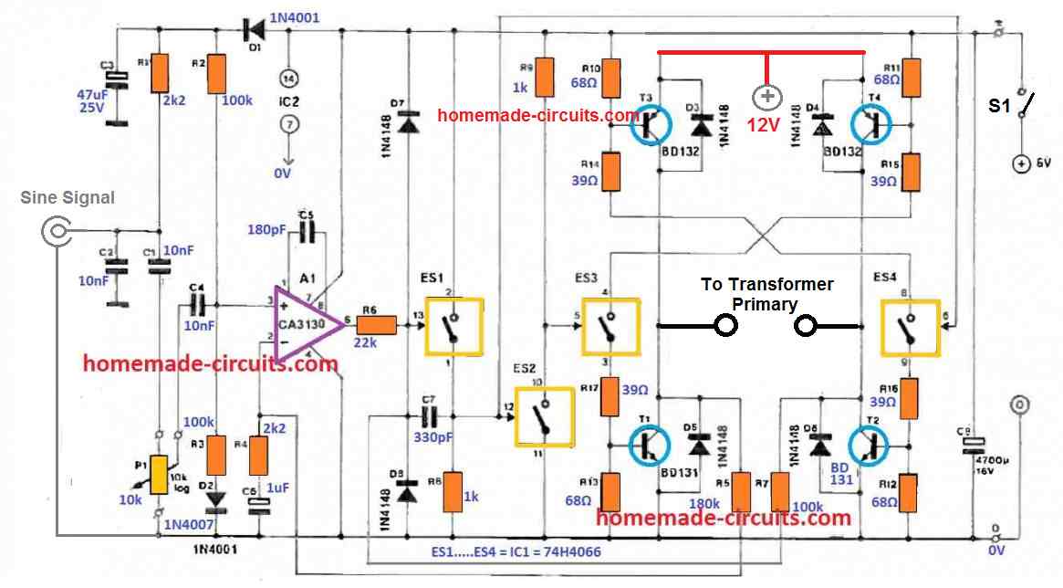
12V to 600V Generator Circuit
A 12 V battery will allow this high voltage converter circuit to produce a voltage of around 600 volts.
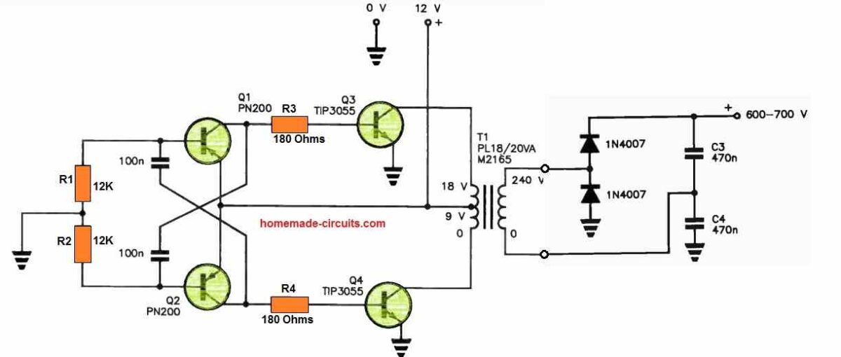
There is no need for an special inverter transformer. T1 is only a standard mains transformer with two 9 V windings or an 18 V secondary that is center-tapped.
Base drive is provided to switching transistors Q3 and Q4 by a flip-flop oscillator employing Q1 and Q2.
The 12 V supply is switched across each half of the 9 V windings alternately by these power transistors, which act as the primary winding in this application.
As the secondary, the 240 V mains winding powers a full-wave voltage-doubler rectifier.
The transformer continues to function well when the oscillator is operating at a frequency of roughly 1 kilohertz.
The rectifier doesn't require any electrolytic capacitors, which saves space, lowers costs, and increases dependability. Only 400 V rated polyester caps [greencaps] are required for C3 and C4.
Because switching transistors have some collector-emitter voltage loss, nine volt transformer windings are utilized instead of 12 volt ones.
It is important to note that Q3 and Q4 should be installed atop a heatsink.


Questions & Answers
please sir, what is the meaning of pcom in high voltage power supply variac
hi how are you
i need to circuit for invert 12v dc to 600v dc 1A
thanks.
Hi Mohammad, you can try the first circuit from the following article, just change the transformer secondary to 600V, or the primary side to 3-0-3V and the secondary 220V winding will automatically produce around 600V, with a 12V battery…
https://www.homemade-circuits.com/7-simple-inverter-circuits/
Dan, It normally means “Power Common” or “Primary Common”
Sir, I am trying to make a step up transformer which can be able to step up 7.4v DC to 1kv AC. So pls how can I make the secondary winding?
Gideon, you can take the help of the following article for the calculations:
https://www.homemade-circuits.com/how-transformers-work/
Dear
in this attached ckt which type of capacitor is used ? polyster or polyprepelne between both transistor collector ?
Hi, Ideally they should be PPC type (polyprepelne)
sorry for error
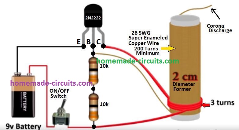
I want to convert 3v dc current to approx 400k v ac
it is possible or not if possible then give me simple circuit daigram that i will make at home
What you need is basically a tesla coil, please can probably try the following concept, but you may need to adjust the coils and the base resistors to work with a 3V DC…
For the circuit labeled “Using Ignition Coil” I have questions:
1) Is C3 a 1uF 400v cap?
2) In another comment response on May 8th 2024, you said
“Please add a 1N5408 diode across the primary winding of the ignition coil
which is connected to the MOSFET. Unfortunately this was not shown in the
original diagram. “. Question , should it be in series with the primary winding?
Question should the diode arrow current direction go towards [12volts] or towards[ the Hexfet that goes onto ground].
thank you Swagatam for all your great diagrams
David
Thank you David, for your questions.
The value of C3 is actually not known to me, it seems like it is hand made by firmly sandwiching an aluminum foil between mica pieces, however, if you want to use this as a high voltage generator, you would not need the D1—D35 diodes and the capacitor, you can simply disconnect the secondary winding from the positive line and use the isolated secondary terminals directly to get the intended high voltage…
The diode 1N5408 should be in parallel with the primary winding of the ignition coil, alternatively you can also add this diode across the source/drain of the MOSFET. If you connect it parallel to the ignition coil primary then the cathode (arrow point) will go towards the positive wire of the ignition coil. If you connect it across the MOSFET drain/source, the arrow will go to the drain side and the other side to source ground.
Let me know if you have any further doubts or questions…
Simplest way to do up to 10kva arc pulse generator without transistor
Arc circuit for gas lighter and include sefty future and 3volt battry supply and battry lavel indicater. Please make this digram.
I don’t have this circuit right now with me. I will try to figure it out soon…
Hello sir. I have no questions. I merely wish to show appreciation for your dedication to teaching the beautiful art of electronics. I recognize a great patience and discipline supporting your well-earned knowledge and I’m so happy to see you share freely. Thank you.
It’s my pleasure! Thanks for your kind words!
How are you sir,
Sir, in the first circuit, can the transistor be replaced with a 2-4 parallel mosfet for high voltage output, then if I replace the transistor with a mosfet, do the 47n and 470n capacitors need to be replaced?
Please explain the circuit sir, thank you very much
Hi Agus,
I don’t think a MOSFET can be used in the first design instead of the BJT. The circuit appears to be built for BJT only. But you can try a MOSFET without changing any other parts and see how it responds.
By the way using a MOSFET will not help you to get higher voltages because the output voltage is dependent on the transformer winding ratio only.
Okay sir
I will try to use a mosfet and I will change the transformer to (12 – 0 – 12) whatever the results I will tell later
Sure, No problem!
Hello, sir
in figure 1 can you use a non-CT transformer (0 volts-9 volts)? with higher output power. Which part should be changed sir ?
Agus, the first circuit cannot work without a center tap transformer, and non-CT cannot be used. You can use the IC 555 circuits for a non-CT transformer.
in the 555 ic circuit how much output power is generated? and how to set the output pulsed ?
You can try the following concept. Frequency to the transformer can be changed by changing the C1 capacitor value. It should around 50 Hz or 60 Hz if an iron core transformer is used:
Hello sir,
I have tried to make the circuit with 555 ic . But for some reason the ic stops working after some time. It only happens if i short the output.
Hello Vivek,
Please add a 1N5408 diode across the primary winding of the ignition coil which is connected to the MOSFET.
Unfortunately this was not shown in the original diagram.
Let me know if you have any further questions.
is R3 used to set the desired frequency?
R3 sets the PWM. You can add a 100K pot in series with R1 to adjust the frequency. C1 also decides the frequency.
Hey swagatam
I’m working on a project and i want to produce an output of around 400v DC from either a 3.3v battery or a 9v battery
Have been trying to build a boost converter but not been able to design one that produces such an output
I don’t have a current requirement so the output current can be very low in milliamps but i want a circuit that’s very compact and small
Would be very thankful to you if you can help me out with this
Hi Saharsh,
You can perhaps try the following circuit:
https://www.homemade-circuits.com/how-to-convert-12v-dc-to-220v-ac-using/
You can ignore and eliminate the feedback components involving the BC547, the zener diodes, the preset etc.
For the coil, you can try a 100 uH inductor instead of the shown 40 uH.
I help teachers with handicapped students do science projects, I showed the students a 555 multivibrator and NTE 264 with an automotive coil to produce impressive arcs. They became excited about making this a science project but most students have very limited hand coordination and minimal soldering skills. Do you know of PCB kits that I might buy to help them make show and tell projects that produce impressive arcs?.
I truly appreciate your efforts, however I am sorry, unfortunately I have no idea from where PCB kits can be procured.
Please let us know the type and value of C3 in your 555 multivibrator and IFR511 spark generator circuit.
Hi Brother Swagatam,
Do you have a shematic wiring diagram to create a Corona Surface Treater Generator?(=to increase the dyne level on the paper to have stronger printing ink/toner cohesion).
I’m a layman who is interested in making it useful for my printing business.
Thanks Teddy Bro,
This project looks complex, let me investigate it, if it is feasible for me, I will surely design it for you and let you know…
This circuit was referred from an external source where the value of C3 was not given. I think you can build it by twisting two 4 inches super enameled copper wires together tightly making sure the two wire do not short with each other.
Thank you for your rapid response to help handicapped students be delighted with electronics.
I am always glad to help!
Regarding the negative ions produced by using an automotive coil, do the negative ions look and sound different than arcs of alternating positive and negative ions?
Yes they are quite different, I included the last concept in this article since it involved the generation of high voltage.