Did you've ever had trouble catching or establishing connection with distant FM radio stations which were broadcasting programmes you wanted to listen to? Perhaps you're aware there are a lot more faraway channels, further than the range of your FM receiver. Of course, you could purchase or construct a stronger FM tuner but, building a tunable FM booster, on the other hand, can be much cheaper and might also drastically increase your FM receivers reception range.
By: Arun Mathur
The components for our FM signal booster circuit will be inexpensive. The two-stage amplifier circuit may be constructed in a variety of ways, and the work should only require just few hours to finish.
The gain of this small circuit will astound you.
The prototype device successfully picked up signals from almost 175 miles away!
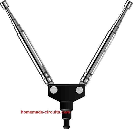
An external telescopic V-shaped antenna is required as shown below.
The FM radio's retractable antenna is hooked up to the input side of the booster, and the increased signal is transmitted to it through a single cable. Once you connect the circuit, you'll need to do a few easy adjustments.
When listening to nearby powerful broadcast FM channels, you should turn off the booster to avoid audio "swamping."
How the Circuit Works
The proposed FM radio antenna booster circuit is a two-stage radio-frequency amplifier, as illustrated in the design in the following figure.
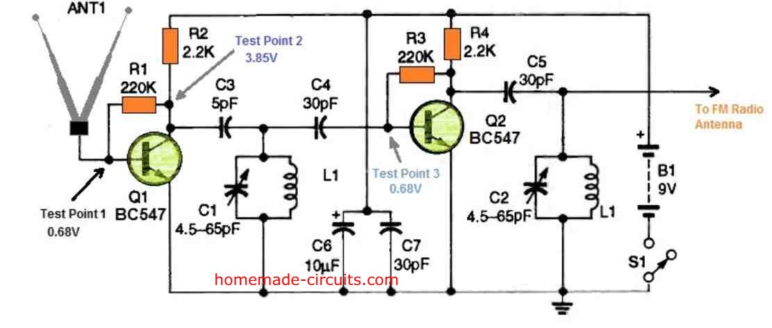
It has a couple of BC547 NPN transistors, Q1 and Q2, that can operate at 250 MHz. The signal from the V-shaped antenna is supplied into Q1's first stage, which is adjusted to provide maximum gain through R1.
The pairing of coil L1 and capacitor C1, which is linked to the collector of the transistor by C3, tunes the circuit to the receiving input signal.
Thereafter, the preamplified signal is delivered to the base of Q2 via C4. The following stage's parts are the same as the first, and the frequency is governed by L2- C2 in the collector circuit.
The totally amplified RF signal is subsequently sent to the FM receiver's antenna via a wire approximately 8 inches long terminating with a crocodile clip from the L2- C2 junction.
Switch S1 supplies power to the adjustable FM booster, through a regular 9-volt transistor battery. The power supply is filtered and stabilized by capacitors C6 and C7 connected across battery input.
How to Construct
The circuit parts are installed on a glass-epoxy circuit board with copper foil cladding and a thickness of 0.040 inch. This may be 1 1/2 x 3/4-inch in size. You may get a completed circuit board from any appropriate vendor, or you could just make it yourself on a stripboard.
L1 and L2, which are pair of hand-wound air-core coils, are employed in the circuit. Wind a 2.5 inch long 20 AWG bare copper wire 1.5 turns around a 3/8-inch diameter spindle or drill bit to make each of those coils.
If you're assembling your own stripboard, use a portable power drill with a fine abrasive disc or circular saw in the tool barrel to eliminate the thin strips of copper foil that constitute the isolated pads over the stripboard.
You may also manually scrap the copper pads by creating parallel incisions with a scalpel blade knife from around edges of each pad and meticulously taking off the thin strips between the broken lines.
Examine the narrow channels with a magnifying lens and an ohmmeter to ensure you don't have any copper burrs between the isolated copper pads that might create an undesired electrical shorting.
You could prefer to place the finished small device in a plastic box for durability. Drill the holes for all external connecting wires and two access holes for tuning capacitors C1 and C2 before positioning the assembly in the plastic box, if you're using this enclosure.
Remember that this FM signal booster's adjustable gain function enhances gain, but also because the circuit is not regulated, this can give rise to oscillation. This flaw could be overcome by carefully positioning and soldering circuit components correctly and not too close to each other.
How to Setup
You must do the following adjustments:
- Stretch the V-shaped antenna to their maximum length and set them at a 90-degree separation angle.
- Attach the antenna leads to the ground plane base (3 x 3 inches).
- Keep the FM booster switch S1 switched OFF, and turn on the FM receiver with the volume control knob in the midway.
- Attach the crocodile clips to the retracted antenna top end on the FM receiver and adjust to a weak hardly audible station around midband. Do not tune and try listening to loud, dominating local stations that could cause the adjustments to be more difficult than they need to be.
- Tweak the C1 and C2 capacitors, then align the V-shaped antenna until you get the best signal from the desired station. The stereo indicator LED on the FM radio receiver should start illuminating as soon as the signal strength is at its greatest, if the station broadcasts in stereo.
- Turn ON the switch S1, and you should see a large improvement in signal strength if indeed the FM booster circuit is functioning correctly. If not, you can check the various test points and confirm them according to the data provided in the schematic.
- If you find the signal intensity dropping and low, the circuit might be oscillating or wrongly tuned. Adjust C1 and C2 carefully to get the better reception output; moving the antenna to different angles while watching the stereo LED indication could also help you judge the best setup for getting maximum signal boost.
- You may have to repeat steps 1–7 for any specific FM station you're interested in. Once you've set the FM booster for a particular band location, you should be able to receive other bands also. To obtain this effect, some further adjusting of C1 and C2 may be required. Be calm until you've figured out how to maximize the gain of the booster. After some trial and error, you should be able to get the best possible outcomes.
Parts List
- All resistors are 1/4 watt 5%
- R1, R3 = 220 K
- R2, R4 = 2.2 K
- Capacitors
- C1, C2 = Between 4.5 pF ans 65 pF trimmer capacitor.
- C3 = 5 pF Ceramic Disc
- C4, C5, C7 = 30 pF Ceramic disc
- C6 = 10 uF/25 V
- Transistors Q1, Q2 = BC547
- L1 = see text
- S1 = SPDT toggle switch
- B1 = 9 V battery


Questions & Answers
fm बूस्टर सर्किट में इनपुट प्वाइंट पर एंटेना का कनेक्शन गलत लग रहा है।
आपने दो टेलीस्कोपिक एंटेना use किये है।इनमें एक सिग्नल इनपुट ओर एक अर्थ होना चाहिए
The antenna does not need to be a twin telescopic antenna, it can any single metal rod, or flexible wire, or any long condcutor….so ground is not needed for this antenna.
Hello Sir,
I am writing to seek your assistance regarding an issue we are experiencing in our room.
We have noticed that FM Radio signals are not being received properly, which is affecting our Best program.
We are looking for a reliable solution to enhance FM radio signal reception within the room.
Here we need to make circuit that receive the outside signal and rebroadcast that signal inside the room so that i can tune any station in my room at any place.
Could you please provide recommendation on the best product or system available for this purpose.
Hello Nitin,
That seems possible! To do this we will need a small FM radio whose output can be integrated with a small FM transmitter. The FM transmitter can be tuned to some standard FM band, which can be then received by your FM radio inside the room… This above FM radio and transmitter unit will need to be positioned somewhere outside the room.
Let me know your thoughts on this…
ok sir…
but your FM booster device will work instead of small radio
or have you any ready circuit or device that can I implement once.
because my room size is big almost 2000 sq ft…
Nitin, the FM booster circuit is intended to be integrated with the existing FM radio antenna, it cannot be used with a transmitter.
You can try the above explained booster circuit by integrating it with your existing FM radio antenna and check whether it helps to improve the performance or not…
Mai apke site gaye ciquit and sujhav Se shantust hoo kirpaya kampleet pcb with components sahit pura bord dikhaye
Interesting, i will try this, thanks for Sharing. ^.-.^ C:
Sure, please go ahead!
I’m indeed satisfied with the article I read on booster. Thanks.
मै वास्तव मे बूस्टर पर पढे गए लेख से संतुष्ट हूँ क्रपया कंपोनेन्ट सहित कम्लीट बोर्ड दिखाएँ तो आपकी अति किरपा होगी धन्यवाद
Parts list is updated at the end of the post. PCB is not available right now.
I am preparing the above booster circuit and i will put review after creating the circuit. mainly i have to check how much effective this circuit.
Thank for providing the circuit.
It’s my pleasure, tank you!