In this article I have explained a 5 assorted power bank circuits using 1.5V cell and 3.7V Li-ion cell which can be built by any individual for their personal emergency cellphone charging functionality. The idea was requested by Mr. Irfan
What is a Power Bank
Power bank is a battery pack which is used to charge a cellphone outdoors during emergency situations when an AC outlet is unavailable for charging the cellphone.
Power bank modules have gained significant popularity today due to their portability and ability to charge any cell phone while traveling and during emergency requirements.
It is basically a battery bank box which is initially fully charged by the user at home, and then carried outdoors while travelling. When the user finds his cellphone or smartphone battery reaching low, he connects the power bank to his cellphone for a quick emergency topping-up of the cellphone.
How Does a Power Bank Works
I have already discussed one such emergency charger pack circuit in this blog, which used chargeable Ni-Cd cells for the intended function. Since we had 1.2V Ni-Cd cells employed in the design we could configure it to the exactly required 4.8V by incorporating 4 of these cells in series, making the design extremely compact and suitable for optimally charging all types of conventional cell phones.
However in the present request the power bank needs to be built using 3.7V Li-ion cells whose voltage parameter becomes quite unsuitable for charging a cellphone which also uses an identical battery parameter.
The problem lies in the fact that when two identical batteries or cells are connected across each other, these devices begin exchanging their power such that finally an equilibrium condition is achieved wherein both the cells or the batteries are able to attain equal amounts of charge or the power levels.
Therefore, in our case suppose if the power bank utilizing a 3.7V cell is charged fully to about 4.2V and applied to a cellphone with a drained cell level at say 3.3V, then both the counterparts would try to exchange power and reach a level equal to (3.3 + 4.2) / 2 = 3.75V.
But 3.75V cannot be considered the full charge level for the cell phone which is actually required to be charged at 4.2V for an optimal response.
Making a 3.7V Power Bank Circuit
The following image shows the basic structure of a power bank design:
Block Diagram
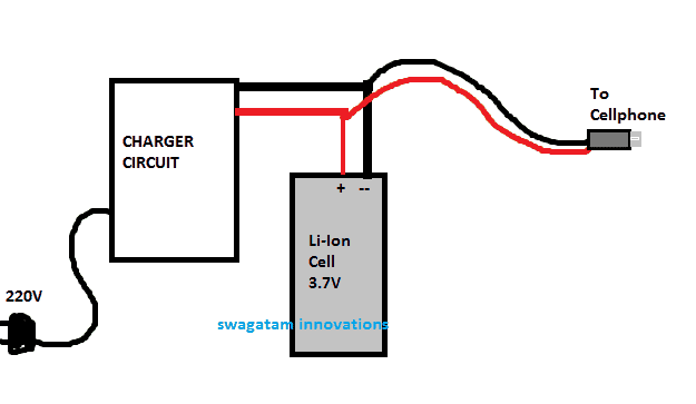
As can be seen in the above design, a charger circuit charges a 3.7V cell, once the charging is completed, the 3.7V cell box is carried by the user while traveling, and whenever the user's cellphone battery goes down, he simply connects this 3.7V cell pack with his cellphone for topping it up quickly.
As discussed in the previous paragraph, in order to enable the 3.7V power bank to be able to provide the required 4.2V at a consistent rate until the cellphone is completely charged at this level, a step up circuit becomes imperative.
1) Simple Power Bank Circuit using 18650 Li-Ion Batteries
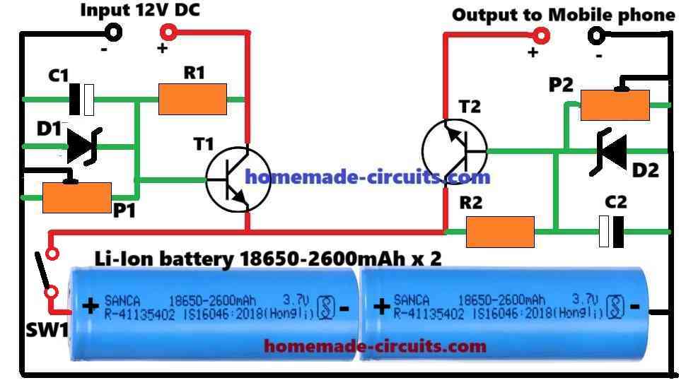
The following figure shows the simplest and the best power bank circuit design that you can build and implement quickly.
Parts List
- Resistors are 5 watt CFR
- R1, R2 = As per the calculations
- C1, C2 = 100uF/25V
- D1 = 9V zener diode 1 watt
- D2 = 6V zener diode 1 watt
- T1, T2 = 2N3055
- P1, P2 = 1k preset
- SPST ON/OFF Switch = 1
The circuit incorporates two identical emitter-follower transistor regulator stages, whose output voltages can be adjusted and fixed using presets.
One regulator stage forms the charger section of the power bank, while the second regulator stage constitutes the charging output for charging a mobile phone.
Input Stage for Charging the Internal Power Bank Battery
One regulator circuit can be seen configured around T1, R1, D1, P1, C1 which forms the input side of the power bank.
This input side is supposed to be supplied with an external 12V DC for charging or topping up the internal Li-ion Batteries of the power bank, whenever they are exhausted.
R1 supplies the base voltage and current for T1. This voltage is stabilized to around 9V by the zener diode D1.
Since T1 is configured as an emitter-follower, its emitter terminal follows its base voltage producing around 9 - 0.6 = 8.4V at the emitter end. The 0.6V is the internal drop of the transistor.
This 8.4V from the T1 emitter supplies the charging voltage for the two 18650 batteries connected in series.
The above 8.4V specifies the full charge voltage for the two batteries (4.2V + 4.2V).
However, since there's no over charge voltage cut-off in this T1 configuration, it is recommended to keep the battery full charge level a shade lower than 8.4V.
Ideally this can be reduced to around 8.2V for an optimal charging of the power bank batteries without the danger of overcharging them.
The 8.2V can be set by appropriately adjusting the preset P1.
Output Stage for Charging External Mobile Phone
The circuit configured around T2, R2, D2, P2, C2 forms the output stage of the power bank.
This stage supplies the output voltage for charging an external mobile phone.
The working of this T2 emitter follower regulator stage is exactly similar to the T1 stage explained above.
However, for this regulator the output voltage is optimized with a 5V output which becomes perfectly suitable for charging any mobile phone or smart phone.
The setting up of the 5V output is precisely done using the P2 preset and the D2 zener diode.
Power bank Resistor Calculations
The resistors R1 and R2 decide how much current can be achieved across the emitter side of the transistors.
These output currents determine how fast the internal battery of the power bank and the external mobile phone can be charged.
R1 and R2 can be calculated using the following formula.
R1 = [Input Voltage - (0.6 + Battery Voltage)] x hFE / Max Charging Current
Assuming the battery voltage to be 7.4 V (3.7 + 3.7), Max charging current to be 1 amp and hFE for 2N3055 = 70, we can solve the R1 value as shown below:
R1 = [12 - (0.6 + 7.4)] x 70 / 1 = 280 Ohms (Nearest Standard Value = 270 Ohms)
Power = 12 - (0.6 + 7.4) x 1 = 4 watts or higher.
R2 = [Input Voltage - (0.6 + Battery Voltage)] x hFE / Max Charging Current
Assuming the battery voltage for charging an external cell phone is 5V, hFE = 70 and Max charging current = 1 amp
R2 = [8.2 - (0.6 + 5)] x 70 / 1 = 182 Ohms (Nearest Standard Value = 180 Ohms)
Power = [8.2 - (0.6 + 5)] x 1 = 2.6 watt or higher.
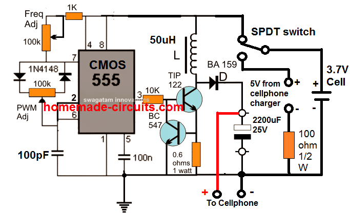
2) IC 555 Boost Power Bank Circuit
3) Using a Joule Thief Circuit
If you think that the above IC 555 based power bank charger circuit looks cumbersome and an overkill, you could probably try a Joule thief concept for achieving quite the same results, as shown below:
Using 3.7V Li-Ion Cell
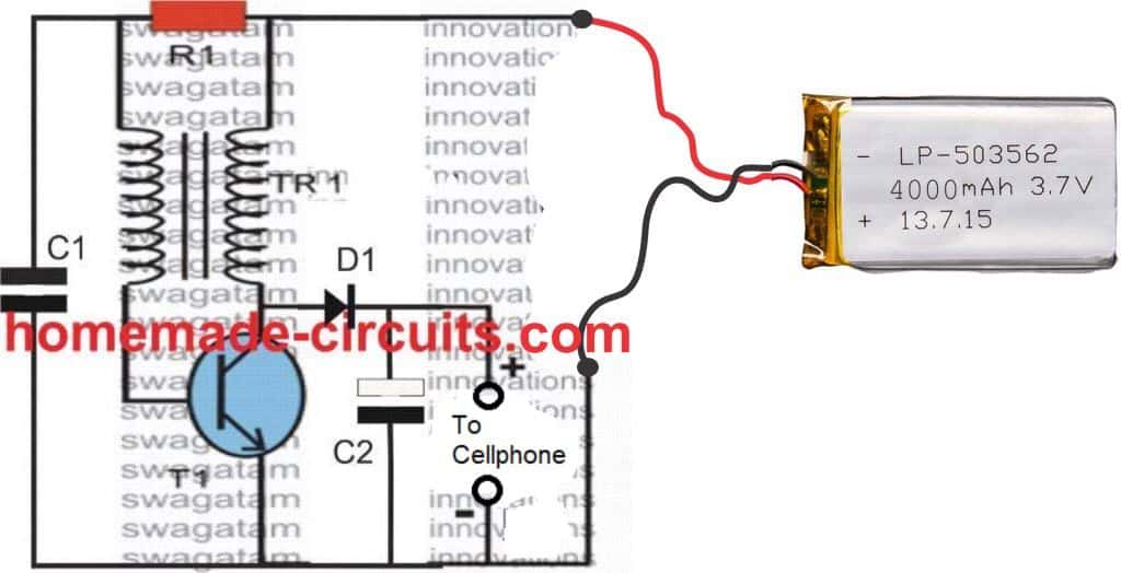
Here, you can try 470 ohm, 1 watt resistor for R1, and 2N2222 transistor for T1.
1N5408 for D1, and a 1000uF/25V for C2.
Use 0.0047uF/100V for C1
The LED is not required, the LED points could be used as the output terminal for charging your smartphone
The coil is made over a T18 Torroidal ferrite core, with 20:10 turns for the primary and secondary, using multistarnd (7/36) flexible PVC insulated wire. This may be implemented if the input is from a pack of 5nos of 1.5V AAA cells in parallel.
If you select Li-Ion cell at the input source, the ratio might need to be changed to 20:10 turns, 20 being at the base side of the coil.
The transistor might need a suitable heatsink in order to dissipate optimally.
Using 1.5V Li-Ion Cell
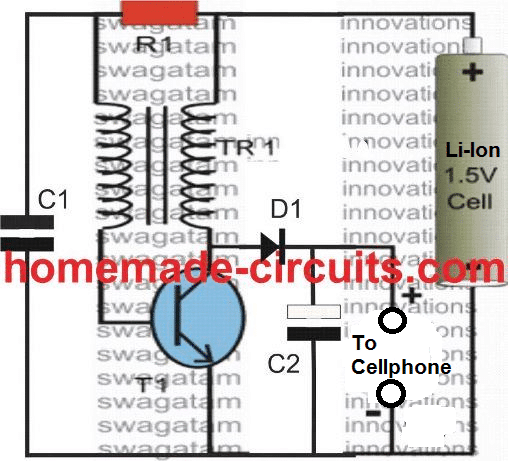
The part list will be the same as mentioned in the previous paragraph except the inductor, which will now have a 20:20 turn ratio using a 27SWG wire or any other suitable size magnet wire
4) Using TIP122 Emitter Follower
The following image shows the complete design of a smartphone power bank with charger using Joule thief circuit:
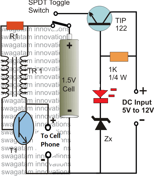
Here the TIP122 along with its base zener becomes a voltage regulator stage and is used as stabilized battery charger for the attached battery. The Zx value determines the charging voltage, and its value must be selected such that it's always a shade lower than the actual full charge value of the battery.
For example if a Li-Ion battery is used, you may select Zx as 5.8V in order prevent the battery from overcharging. From this 5.8V, the LED will drop around 1.2V, and the TIP122 will drop around 0.6V, which will ultimately allow the 3.7V cell to get around 4V, which is just around sufficient for the purpose.
For 1.5V AAA (5 in parallel), the zener could be replaced with a single 1N4007 diode with its cathode towards ground.
The LED is included for roughly indicating the full charge condition of the connected cell. When the LED lights up brightly, you may assume the cell to be fully charged.
The DC input for the above charger circuit could be acquired from your normal cellphone AC/DC charger unit.
Although the above design is efficient and recommended for an optimal response, the idea may not be easy for a newcomer to build and optimize. Therefore for users who might be OK with a slightly low tech design but much easier DIY alternative than the boost converter concept might be interested in the following configurations:
The three simple power bank circuit designs shown below utilizes minimum number of components and can be built by any new hobbyist within seconds
Although the designs look very straightforward, it demands the use of two 3.7V cells in series for the proposed power bank operations.
5) Using Two Li-Ion Cells without Complex Circuit
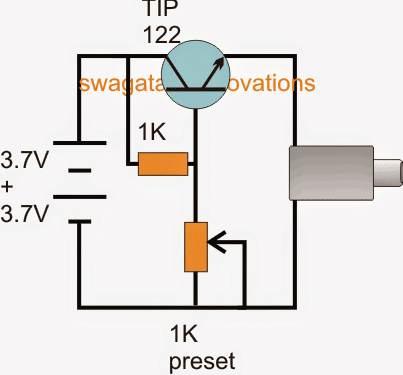
The first circuit above makes use of a common collector transistor configuration for charging the intended cellphone device, the 1K perset is initially adjusted to enable a precise 4.3V across the emitter of the transistor.
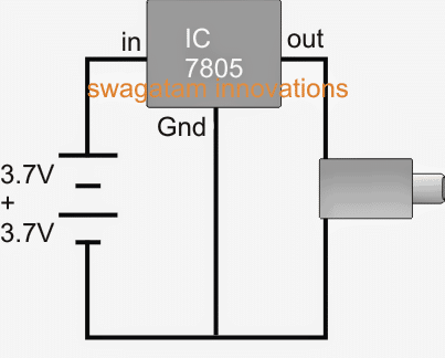
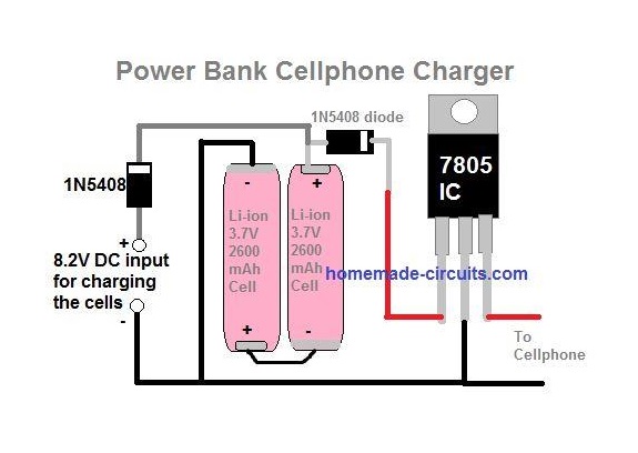
The second design above uses a 7805 voltage regulator circuit for implementing the power bank charging function
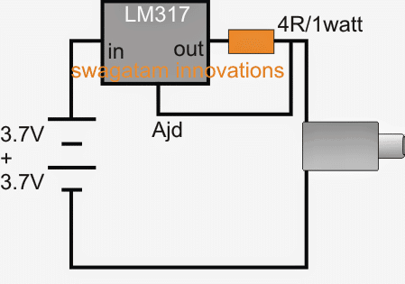
The last diagram here depicts a charger design using an LM317 current limiter. This idea looks much impressive than the above two since it takes care of the voltage control and the current control together ensuring a prefect charging of the cellphone.
In all the four above power bank cell phone charger circuits, the charging of the two 3.7V cells can be done with the same TIP122 network which is discussed for the first boost charger design. The 5V zener should be changed to a 9V zener diode and the charging input obtained from any standard 12V/1amp SMPS adapter.





Questions & Answers
Thanks sir.. there is some confusion for me.
1- Is it control the discharge levels of Li-ion cells..
2- is it control the over charging of Li-ion cells…
3- is it delivers the 2amp for smart phone sharge
Once again thanks for the circuit… B-)
Irfan, the cell will not discharge unless connected to a cell phone
the cell will not overcharge but when the indicator lamp shuts off you should remove the input supply…
2amp may be obtained if the cell is rated at 3000mAH
Also tell where charging pin or female usb connector is attached…?
and which point is used to connect the cells…
And how much cell we connect in this circuit…
Irfan, Everything's shown in the diagram, I am sorry if you are not able to understand the diagram then it would mean that you are very new in the electronics field, and this circuit can be extremely difficult for a new comer…so I think you should rather try the other 3 circuits instead of the first….
Thanks sir for this circuit
What is the output amp in 1st circuit
I want 1 amp output from 1st circuit
Thank you very much
Mayank, you can calculate and change the 0.6 ohm resistor for fixing the desired current capacity of the circuit…accordingly the cell mAH will also need to be upgraded to the intended level
sir this circuit can give cAPAcity of 10000 mah ?
the formula for calculating the resistor is
R = 0.6 / max current output (amps)
Sir the circuit above is so interesting.
Is there any idea that can modefie or improve the above circuit like for example adding of a small solar panel to charge up the battery 3.7v.
Thanks Angelous, yes definitely you can use a suitably rated solar panel and use it to charge the 3.7V cells.
sir why did you used bulb? it is possible to change that into the red LED?
Bulb will pass sufficient current for charging the battery and also indicate the situation, LED will not pass sufficient current and will not serve purpose, it will remain lit forever, not allowing the battery to get charged.
LED will require an external circuit for the indications… which can make the circuit more lengthy…
i have been waiting for so long for this kind of circuit
i will definately build it sooner n give updates thanks for this BOSS SWAGATAM
you are most welcome Adesina!!
good post sir, what is the max current of the last current control circuit, can we build boost converter using attiny micro controller and a 7 segment display interface , i want to increase efficiency because i used 6*1.2v 2700mah which doesent charge my 2000mah android a single time the 7805 getting heated up and a lot of power is wasted there, i bridged 2 7805 ics together but there is no improvement the charging current is very low 150ma i connected directly 4 cells without any regulator and the phone got charged with with 1500ma current but due to voltage fluctuations the charge controller in the mobile disconnecting the power source. any help is appreciated thank you sir.
Thanks Seelamsetti,
just use 4 of the 1.2V cells in series and connect the output directly to your cellphone, no need of using a 7805 IC, as shown below:
https://www.homemade-circuits.com/2012/11/homemade-cell-phone-emergency-charger.html#
yes MCU can be used for making a power controller circuit
…if your cellphone is disconnecting the power due to fluctuations then you can add another pack of 4 cells in parallel or try bigger 1.2V cells
thank you sir
Hi sir,
Can you please help me to make a 3.7v mobile battery level indicator, I want to do this by using ATtiny85, for this I have use concept of voltage divider, so I have taken Vin as 4v, R1 as 130 ohm and R2 as 910 ohm for 3.5v Vout.
Thanks.
Hi Pawan, sorry, I do not know how to do it with a ATtiny85….
Hi Swagatham
For Ni-Cd cells, the charging current is calculated by deviding 'Battery capacity Ah/10'.
How can I calculate the safe charging current and charging timeof Li-Ion and Li-Po batteries….?
Hi Anil,
as a rule of thumb for Li-ion and Lipo batts you can use a charging current as high as their AH level…so for example if the AH of the battery is 2AH then the charging current could be 2amps, but the temperature of the batt could be crucial and will need to be monitored manually or by some automatic method
Sir this powerbank is 3.7V to 5V/2A ? Right? So how about if the battery is at 4.2V What will the output .. ?
and also i want to rem0ve the bulb …and replace it with led and resistor c0nnected to supply batt. Or output ? How can i done this?
Romeo, you can adjust the PWM pot to get a precise 4.2V
the bulb is a safe and an easy option to verify the charging condition…LEd indicator will not work in that position and might require a complex circuit using an opamp
Sir curcuit is good but a bit complicated
And also please tell me which type of bulb used in curcuit
A tourch bulb ?
Prince, you can use a 3V torch bulb rated at 200mA or above.
And also please tell me how much volt requierd for charging a 18650 cell
it's same as described above…4.2V
I would like to know what are the theories used in creating a power bank?
Thank you.
respected swagatam
my powerbank charging only 10 scecond then auto cut off why?
if i can make another one with its 2 battery (3.7v*2ps)–if that batteries are sutable for ur circuite used LM317 ic –is this ic will heat-
Hi AZ, check the voltage with a voltmeter while the cell is charging, it could be reaching the full charge value quickly…this may be because your charging current is high,,,,check this first
sir how i can check a 7805 ic
you can do it by actually supplying an input voltage across the specified pins and checking exactly 5V across its output pins
you can calculate it through the link given in the article….or do it with some trial and error….please read the full article for knowing the details.
How much baat including in perelal and improve the nex by nex Mobil charj
Can i replace 3.7v battery to 6v lead acid? It is compatible??
yes you can do that
Well done sir, I tried to charge my power bank with combination of three cells from laptop battery, I don't know their capacity. So my power bank leds that used to be off, now is always on blinking as if it's charging whether is not connected to a charger. Please do you know what might have happen to my charger and how-to rectify the problem?
Arhyel, what is the input specification of your power bank?…this specification will help us to know how much input is required to be fed safely to the unit…if it was more than then your PB could be damaged
Thanks a lot sir, nice design. I can't find the charging unit and battery connector on the 3rd simply diagram.
thanks Ochin, the charging of the 3.37V cells can be done through any standard adapter externally.
in the last paragraph I have mentioned the word "LM317 charger" with reference to the cellphone which is supposed to be charged using the shown emergency power packs.
the battery of the power pack needs to be charged from an external charger which could be your cell phone charger unit
Sir IAM USING LGABB41865 BATTERYS
OF 5 BATTERYS SINGLE BATTERY HAVE
2600mah TOTAL 5 BATTERYS mah of 13000 mah because please give circuit for that power bank charging and out of 1amp and 5volts please help me sir
give all the specifications correctly
Sir there is a large power loss in case of second circuit using ic 7805. Is there any way to minimize the loss?
you can try a buck converter circuit instead
Hello Sir I'm now in 5th from ECE branch i wish to be design a Power bank. Sir… Of 10000mAh capacity Sir… Help me Sir
Hello, please provide all the technical details of the power bank, as per your specifications.
THANK YOU SO MUCH SIR
FOR YOUR USEFUL CIRCUITS AND EXPLAIN .
You are welcome