In this post I have explained how to design an intriguing LED light effect that generates a collapsing metor shower like appearance. The idea was requetsed by Mr.Pinto Mondal.
Technical Specifications
I am very grateful of your work. Sir I want to make a circuit,which available in the market like 1 or 1.5ft long led light stick and the led flow's from up to down ,like water flow's slowly down from up.
so please sir help me out the circuit, the name is "rain tube led string" size 50cm on Internet I found another name hot meteor shower
Thanks
Pinto Mondal
What is LED Meteor Shower
As the name suggests, the proposed meteor shower or rain tube LED light circuit imitates a falling meteorite, collapsing in the sky.
Some of the other names for this project can be as given below:
- Falling LED light circuit
- Dropping LED Light circuit
- Slow Fade Running LED circuit
- Shooting Star LED Effect Circuit
The effect begins with a sequentially incrementing bar graph type of illumination which suddenly begins collapsing from the rear until its completely OFF, the effect keeps on repeating, quite resembling a chasing and collapsing meteorite in the sky.
When connected in groups, the visual experience can be quite a mesmerizing.
UPDATE
While practically verifying the circuit I found that the meteor shower effect could be improved and made more powerful by introducing the LEDs at the collector side of the transistor.
The revised circuit diagram can be seen below:
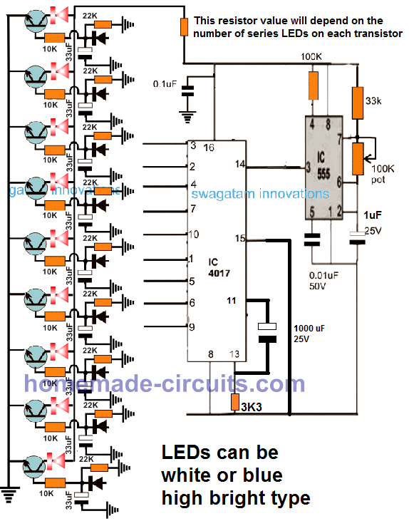
Parts List
All resistors are 1/4 watt 5%
- 10K - 9
- 22k - 9
- 33k - 1
- 100k pot - 1
- 3k3 - 1
- 1N4148 - 9
- IC 4017 - 1
- IC 555 - 1
- BC547 - 9
- LEDs Blue/RED - 9 to 36 (1 to 4 in series on each channel)
- 33uF/25 - 9
- 1uF/25V - 1
- 1000uF/25 - 1
- 0.1uF - 1
Note: The 100K on IC 555 pin#4 can be removed and pin#4 connected directly to the positive line.
The 1000uF can be reduced, if the 3k3 is increased proportionately.
Video Demonstration
PLEASE IGNORE THE DESIGN DISCUSSED IN THE FOLLOWING SECTIONS BECAUSE IT IS AN OLDER DESIGN AND HAS NOT BEEN VERIFIED THROUGH PRACTICAL TESTING.
Circuit Diagram
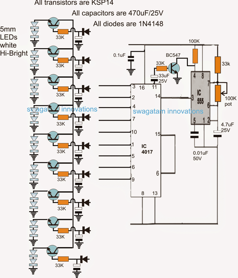
The idea could be achieved through the circuit represented above, using a Johnson's decade counter and a 555 astable clock generator circuit.
How it Works
It's basically a LED chaser circuit with a delay effect that's introduced at the base of each LED driver transistor. The charge stored in the capacitors hold the LED illumination for some moment until shutting them off gradually at the same sequencing rate as these were earlier illuminated....creating the fading collapsing effect of a meteor shower.
The IC 4017 outputs produce a jumping high or shifting logic high across its pin#3 to pin#9 in response to the clock signals fed at its pin#14 by the IC 555. The speed of this sequencing can be adjusted and tailored as per preference with the help of the 100k pot associated with pin#7 of the IC 555
The sequencing begins from pin#3 of the IC 4017 and proceeds until the sequence reaches pin#9 of the IC, during this course of travel, the LEDs illuminate in a bar graph form, due to the holding charge within the base capacitors of the transistors.
By the time the sequence reaches pin#9, the capacitor across that bases of the transistors begin losing there holding power as these are discharged sequentially, such that the LEDs too begin shutting from pin#3 towards pin#9, until all the LED are shut off.
However until this process is completed successfully, the IC 555 must somehow be disabled otherwise the sequence will reset back to pin#3 of the IC 4017 before the LED are able to shut off for evolving the desired meteor shower effect...and the whole purpose of the design might be nullified.
In order to ensure this, as soon as the sequence reaches pin#9, and subsequently to pin#11, the pin#11 holds pin#4 of the 555 to ground disabling the IC for some moment until the fading or the collapsing effect of the sequence is implemented across the LEDs. The time delay responsible for this must be precisely set by adjusting the base resistor of BC547 transistor at pin#11 of IC 4017.
If you are not interested to include the above explained pin#11 stage, the other alternative is to use the LEDs driver stages only up to pin#5, and allow the remaining pinouts to be blank, such that the sequencing logic while crossing these blank pins provide the required time delay for the collapsing effect to complete.
The idea can also be implemented using 1 watt LeDs for enabling brighter and more robust meteor shower LED effect....the only change required for this would be to replace all the transistors with TIP122,and make sure the LEDs are mounted on adequately large heatsinks.
R/C Delay Components Selection is Important
In this circuit the timing resistors and capacitors across the transistor bases play an important role for enhancing or degrading the desired meteor shower light effect...therefore the values must be selected carefully and tweaked through experimentation until the most impressive outcome is achieved.
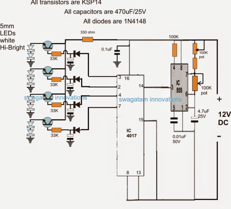
The above circuit can be simplified to an extent by implementing the modifications as shown in the following image, although the effect will not be as interesting compared to the original design, the LED meteor shower effect will be still effectively displayed.
Simplified Schematic



Questions & Answers
Thank you very much sir, for making the circuit so fast.now I have two questions & a request ,the question is 0.1uf cap is it Polly cap & volt value is?and the circuit is it powerd by 12v DC & the connection(- +)is ,need any current limiter circuit. Now the request can you please tell me what's the change I have to made for making this kind of effect. https://drive.google.com/file/d/0B_REIZgLatu2UWtzVjlSMlhaNXM/view?usp=docslist_api
Pintu, yes, the show circuit can be expected to give approximately the same results as shown in your video….
0.1uF cap can be a disc ceramic capacitor,
please read the section shown in bold letters for other info
Sir, in our area there are no ksp 14 transistor so, can we have any similar transistor
Sir, in ic- 4017 pin 6 connect with pin15, is it pin 6 or pin12 and you told that pin 15 not connect with pin 6 or 12 connect with ground, then pin 6 or 12 remain open or what?
Pintu, don't use the transistors initially….do it in this way:
first chnage the resistor after the diode to 1K…and then connect the LEDs directly across the end of this resistor and ground….do this for all the outputs…and check the response.
pin12 is unused
pin15 is connected directly with ground
pin6 is one of the outputs…please see and do it carefully…
Dan – Abuja Nigeria
Sir I am a regular visitor to your blog and I find it very interesting I have a request for your assistance. I have a 2KVA rated Liebert UPS running on an internal battery consisting of 8 pieces 12v 7amps rating all connected in series. Now I have an external battery bank of 8 pieces 12v 18amps also connected in series I have not yet attached it to the ups until I can find a circuit that can independently charge the external bank. please assist me in this regard, with a cct. that can charge the 8 batteries in series Thank you
thanks Dan! you can simply use a 0-12V/ 2amp transformer, connect a bridge rectifier to it using 1N5408 diodes and connect the output to each battery individually through a 5amp FSD ammeter….when the ammeter needle falls to zero you can assume the batt to be fully charged, you an do this to all the battey one by one
or make 8 such units and connect to the 8 batteries for charging all of them simultaneously.
if you are interested to include an automatic cut off, in that case you can include the second circuit from the following article in between the battery and the 12V/2amp power supply:
https://www.homemade-circuits.com/2011/12/how-to-make-simple-low-battery-voltage.html
Sir
Thanks for your prompt response, going by your explanation it looks a bit cumbersome to build several circuits to recharge these batteries individually. however, as I earlier mentioned the internal batteries are all connected in series and are charged simultaneously by the UPS that being the case I thought I could have a circuit that can charge the external Bank.
If that is not possible how about grouping them into 4 making 48Volts into 2 for the purpose of charging them. meaning connecting 4 of them in series and charging them.The link you referred me to is not opening thanks for your advice
Daniel, If you wish, you can charge the batts in series, but it's never recommended.
the link is opening here in my computer, you might have not copied it correctly…please check it again by copying the entire link and opening it in a new tab.
Sir, the circuit is not working.i am powering the circuit with the mobile charger and nothing happen. sir,the cap before led is it 470 uf, because they are big.what what would be the possible problem.
Pintu, the circuit may not be working because there might be faults in your connections or parts.
Are the LEDs running from pin3 to pin11?
first make sure the LEds at least shift from one pin to the other…after that we can fix the delay time factor…
initially keep the pin11 circuit disconnected or simply remove this stage.
Yes sir, l made many mistakes in this circuit so my circuit not working now I am doing it on bread board and asking you two parts value, can I use Ecap 4.7uf/63v instead of 4.7uf/25v and 2A103k instead of 0.01uf/50v
yes, both the mentioned capacitors will work….
and you will need to include the transistors also….initially you can try BC547 with 5mm LEDs
Sir, can pot resistor get damage by heat of soldering iron
no pots will not get affected with soldering heat…unless it's held for too long
Sir, I want make more faster blink ,not the two led I need, I want 1 led the blue one blink and little faster what's the change I have to made ,in this video https://drive.google.com/file/d/0B_REIZgLatu2eFc1eFBCX0hWdm8/view?usp=docslist_api
….reducing the 33k resistor or the 4.7uF cap will make the blinking rate faster
Sir, this is not the meteor shower led light it's blinking led light please see the video
yes it's not LED meteor shower because you have just anything as per your own wish and will….it's not my circuit….it's your modified circuit.
Sir, I am new in electronic and the meteor shower circuit you gave me its more big then I thought specially the led portion and I think my bread board not enough to hold the full circuit so I am buying some time to think and doing some small ic circuit to make some confident, can I make one led at the end instead of two
Pintu, I'll try to make it little short for you…then you can try.
I'll make it 4 LEDs….2 LEDs will not produce the required effect.
Thank you,sir
Sir, I am waiting
Pintu, it was updated on the same day, please see the last diagram….
Sir,Sorry for the comments, one thing I am asking you can I use two 10w smd led or one 20w led on12v 2amp smps if yes do I need any limiter circuit or resistor
Pintu, yes you may use it, but you will need a current limiter in the middle as described in the following article:
https://www.homemade-circuits.com/2013/06/universal-high-watt-led-current-limiter.html
Sir, the led wattage divided by led forward voltage = led amp, is it universal formula?
yes it is an universal formula…
Hi Swagatam,
There's an error in your schematic…. There are 2 pins 6 in the 4017….
Please check it.
Best Regards.
Nélio
P.S. Keep up the good projects.
Hi Swagatam,
Me again… you say in the text that pin 15 of 4017 should be connected to the ground…. what about pins 8 and 13?
Best Regards,
Nélio.
Hi Swagatam,
I read the text again and noticed that pin 8 of 4017 connects to – … this means ground, as pin 15?
Best Regards,
Nélio.
Thanks Nelio, yes you are right.
the diagram was lifted from one of my other articles, and I forgot to correct pin15 connection as per the present requirement.
Pin8 and pin13 are already connected to ground and is shown in the diagram, therefore I only pointed towards pin15 because this pin which is incorrectly shown connected with pin6 needed the correction.
dear sir ,
great job by u,thanks.
i want to know how can i run 5w/500ml.amp.led run on 12v/7.5ah lead acid battery.
i connect it with 15ohms/10watt resister but light is very low.can i run this led without any heat sink and resister.
Dear Bashir, please specify the voltage rating of the LED, or you can use the following formula to get the resistor value;
R = Battery voltage – LED voltage rating / LED amp rating
Hai sir, how can I possibly increase the no. Outputs from 9 to say 15 or so in?
Hi Jacob, you will need to cascade two ICs, and get 18 outputs
Hi Swagatam,
I would like to try this circuit because of the great effect.
I am having trouble to find the KSP14 transistor. Could a replacement be the MPSA13? Also a Darlington NPN transistor. Or another Darlington transistor? Maybe a 547 and 558 coupled as Darlington?
cdn-reichelt.de/documents/datenblatt/A100/MPSA13_CDIL.pdf
Best regards,
Henrik
Hi Henrik, you can use any form of Darlington NPN transistor for the purpose, but make sure the current of the transistor is rated much higher than the LED current
Hi again,
Thank you very much
Sir I live in kolkata, naihati. Here ksp14 Darlington non transistors not available .so pls refer ksp14 equivalent transistors.
mahadeb, you can use TIP122, or make Darlington pairs using BC547 and 2N2222 together for each channel.
Dear Swagatam,
I am having trouble with this circuit. When I connect 12V to the circuit nothing happends.
I hope I have understood your answer to Pintu (November 20 2015) correct with only 1 LED at each output of the 4017.
The current usage is only 10 mA.
In order to try to find the error I removed the BC547 transistor to make sure I got a clock from the 555.
With the transistor removed all LED’s lights up.
Connecting an LED to pin 3 of the 555 gives light, but not a pulse (blink).
Please take a look at my PCB layout and tell me if I have made an error.
https://1drv.ms/f/s!AuZaLQUHZG7QZ-olZded8OnaDgs
Best regards,
Henrik
Dear Henrik, even if the 555 does not oscillate, still all LEDs across the 4017 output cannot light up, because the 4017 is designed to illuminate only one LED at a time…so this is something which you may have to check additionally.
As far as the 555 IC is concerned, the circuit is correct and it should show an oscillating output at its pin#3.
I think you should have first finalized the design over a general purpose board and then designed a PCB, because unless a circuit is confirmed practically you could have multiple problems in the PCB layout.
Sorry I having difficulty in viewing your PCB, the zoom-in is not responding properly due to some reason….you can take help of the second design in the following article and use fixed parts for acquiring the 2Hz frequency at the pin#3 of your 555 circuit:
https://www.homemade-circuits.com/p/ic-555-calculator.html
if still it does not respond then your IC could be faulty.
….I guess your IC 555 might be oscillating too fast and that's the reason it's pin#3 is showing a constant glow and the 4017 outputs are all lit up….try increasing the 555 capacitor value to some higher level, until the blinking comes to a slower distinguishable level…
Dear Swagatam,
Thank you for your fast reply and effort always to help.
As you guessed my 555 was oscillating to fast. I had accidently used a 4,7 nF capacitor instead of the 4,7 uF. Changing the capacitor to the correct one fixed the problem with the too fast oscillating.
Now I have another problem. The LED’s illuminates once only. By switching the power off/on the LED’s illuminates once again.
I though the problem was my transistor not resetting the 555 and changed it but without success.
I don’t have a 33uF in stock (pin 11) so I used a 47uF instead. Could that be a problem?
The LED at pin 3 of the 4017 (first output) does not illuminate. Does that have anything to do with the above fault? The LED is OK
Thanks Henrik,
The idea is simple, as soon as the logic reaches pin#11 of the IC 4017, the 33uF initially triggers BC547 into conduction which jams the 555 IC oscillations and therefore the IC4017 sequence stops for a moment.
However as the 33uF charges up may be within 3 or 4 seconds and gets full charged, the BC547 is no longer able to hold the conduction and it releases the IC 555 which again starts oscillating and allows the IC 4017 to start a fresh cycle.
If your IC is permanently getting jammed then perhaps the 33uF cap or your 47uF cap could be leaking current which might be keeping the BC547 permanently ON.
Please note that the polarity of the 33uF is incorrectly shown, it should be the other way round, meaning its positive should be towards pin#11.
Coming back to the issue, you can try connecting a diode in series with the 33uF or 47uF to prevent the leakage current, and see if that helps….
pin#3 should illuminate in any case….connect a capacitor very close to the (+)/(-) pins of the IC4017 and see if that corrects the issue.
Thank’s a lot Swagatam,
You are the best.
I changed the capacitor to another brand and changed the polarity as you described.
Now it works as expected and the LED on pin 3 is also working.
Again thank you,
Henrik