In this article I have explained a simple 1000 watt LED flood light circuit which can be very easily made by even a layman. The circuit was requested by Mr.Mike, let's know more about the request and the circuit details:
Technical Specifications:
Hi from Canada !! My name is Mike . thank you for your work . would it be possible for you , if you have time ! to make me a design for a 1000 watts electronic ballast for metal halide lamp ? a variable one would be even better . I have 120 volts here, Something simple to build if possible thank you very much and Happy New Year Mike Analyzing the Circuit Concept
Hi Mike! Thanks!
A 1000 watt ballast will be difficult for me to design, I tried to find it on the net but I couldn't find any.
By the way you can go for LEDs instead of the proposed type of lamp for better efficiency and light.
And a Happy New year to you, too!
Regards.
Designing a 1000 Watt LED Lamp
A 1000 watt LED lamp can be designed either by connecting 1000 nos of 1 watt LEDs over a suitably designed PCB or by using 10nos of 100 watt LEDs togrther.
In fact a 100 watt LED module would also consist of 100 nos of 1 watt LEDs wired up internally.
The unit may be designed by incorporating 10 nos of 100 watt LEDs in parallel for generating the intended 1000 watts of white flood light.
The design would not involve much complexity, all the 10 modules can be connected together in parallel with their respective current limiting resistors.
Since each 100 watt module would require a maximum 36V, the current consumption would be around 100/36 = 2.7 amps. Therefore the limiting resistor would be R = (36 - 32)/2.7 = 1.5 Ohms/ 5watts.
32v is the assumed forward voltage of the 100 watt module.
However there's one drawback with the above design, it requires a 36V supply which is a pretty odd value and it would be difficult to acquire a suitable smps or a transformer with this rating.
Integrating 1000 nos of 1watt LEds might look a very time consuming task but it would provide you the liberty of designing the module for any desired voltage source.
For example if you wanted the module to work with a 12V supply you could wire 3 nos of these LEds in series and connect all these series in parallel. Similarly with a 24V supply 6 nos could be wired up in series and then in parallel.
Preferably, using 1 watt LEDs looks more comfortable as these can be tailored as per user preferences.
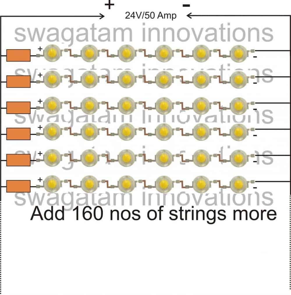
The following diagram shows how to wire 1 watt LEDs in series and parallel for implementing a 1000 watt flood light circuit.
For making the wiring easier, a 24V supply is selected here, which allows us to put 6 nos of 1 watt LEDs in series and make appropriate numbers of them in parallel so that the end value reaches close to the 1000 watt mark.
Calculating the Current Limiting Resistor
In all 1000/6 = 166 nos of strings can be used here, due to lack of space all the connections couldn't be included in the diagram. The resistor value is again found with the help of the formula:
R = {24 - (3.3x6)}/0.3 = 14 ohms
wattage = {24 - (3.3x6)} x 0.3 = 1.26 watts or simply using 2 watt will be fine
The assembly should be done over a aluminum based heat absorbing type of PCB.


Questions & Answers
Hello swahata sir after a long time contacting you .. i hope you and ur health is fine…
How can i make 100 watt LED Flood Light Circuit
Thank you Nazim, you can try the following circuit
https://www.homemade-circuits.com/make-hundred-watt-led-floodlight/
The supply input can be taken from a standard adapter or you can build an appropriately rated transformer based power supply
Hi I want to make a 1800 watt flood light but my main worry is how to remove the heat at would be generated over time, any recommedation
Hi, You will have to use large heatsinks with the concerned devices and also use fan cooling for the same, in order to keep things in control
thank you Anders, you may be right, appreciate your valuable feedback.
I'd like to point out that luminescence and brightness is calculated differently with LED. to be honest I have not grasped it completely myself. But converting lumens to lux seems to give me expected output. One could also used mcd and candela to get an approximation of brightness.
hi sir
what is supply circuit for 12volt/ 50 amp? actually i want to drive 100no of 1 watt led. how can place Led? i already asked question in 100 watt LED tubelight blog regarding placing LED in ceiling i think above article is useful for me but how can we drive? Any LED drive circuit?
Hi Ashok
You won't need 50 amp, just 10 amps would be enough. It can be from a 12V/10amp AC/DC adapter.
I have explained the wiring details in the above article with the formulas.
For a 12V supply make LED strings of 3 x 33, calculate the resistor values as per the given instruction in the above article.
Use adequate heatsink for the LEds, and a cooling fan if possible for extreme safety
50 is the amp or current rating of the trafo
Sir,
what is the ampere rating of Transformer 24v ? 50 in 24v/50 refers to cycles ?
I was reading all the comments and helps me understand my project… thanks for your time and all the help you provide us.. God bless you and your family….
My Pleasure Wilder, God bless you too!