In this article I have explained a simple LED indicator timer circuit which can be used with board games for indicating the elapsed time or the time consumed by the player to complete his or her turn. The idea was requested by Mr. Shane Robins.
Technical Specifications
Hope all is well with you. I am relatively new to circuitry and I am looking to create an DIY indicator light circuit. I would like my indicator light to be green for approx 35 seconds, then turn yellow for 10 seconds, and then turn and remain red until the circuit is shut off. It can be three different lights or a multicolor light, battery powered with low voltage (9V or less). The circuit must reset the timers once power is cycled off and back on again. I have tried circuits utilizing transistors, capacitors, and relays but was unsuccessful. If possible, I would like to avoid Arduino boards/programming. Is this a possibility in your opinion? If so, would you be able to provide me with a wiring schematic to achieve this?Thank you for getting back to me so quickly! We play a board game called Settlers of Catan and my roommate takes forever on his turns. I want to have a system to limit turns without using a timer. Really its just an excuse for me to build a circuit because I'm really interested in it. I would really like it to be portable and with low voltage. Like a 9V or better yet 2AA in series fro 3V.
The Design
The proposed LED timer indicator circuit can be implemented with the help of the following simple circuit idea.
This configuration has been employed in many different circuit applications so far in this blog, and it seems to be pretty versatile with its range.
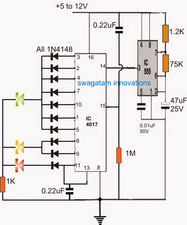
The IC 555 is a configured as an astable circuit for generating approximately 2.5 second ON/OFF duty cycle, which is fed to the clock input of the IC 4017 pin#14.
In response to every positive or ON cycle edge of the 555 output, the IC 4017 outputs jump with a positive logic from one output pin to the next one in sequence, starting from pin#1 until pin#11.
This implies that initially pin#3 is high, then after a clock cycle of 2.5 + 2.5 second ON+OFF time, the logic high from pin#3 jumps to pin#2, and so on until pin#11 is reached.
In the diagram pin#3 to pin#5 can be seen joined and terminated to a green LED, which ensures that as long as the logic high is jumping across these pinouts, the green LED stays switched ON, and since the total time taken for the logic high for crossing these pinouts 5 x 7 = 35 seconds, the green LED remains ON for this period of time, as requested by the user.
Once the above time frame is elapsed, the green LED shuts off, and the yellow LED illuminates, the logic high now travels across the pin number 6 and 9, and quietly identically keeps the yellow LED switched ON for 5 x 2 = 10 seconds.
Finally, the logic jumps to pin#11 of the IC, shutting off the yellow LED, and illuminating the red LED.
However since the pin#11 is also connected with pin#13, latches the IC into this position permanently. In this position the IC stops responding to the clocks fed by the IC 555, and the red LED stays locked and illuminated in this position until the power is switched OFF and switched ON again.


Questions & Answers
Sir i dont know if this is the proper place to request my help but since i dont have your email address i just decided to comment here, Please i am in dear need of a heater schematic, i am in need of a simple Nickrome heater schematic that can run with 24 to 50 volts dc and if it can be regulatable via the applied voltage accross the wires, i am just a little worried connecting the dc current accross the nickrom wires, i wonder if it will work but i just needed further assistance.
thanks and i will be looking forward to read from you….
my email address is (dnkwenti@gmail.com)
Deogratia, If the Nichrome wire is 50V rated then it will heat up correctly at 50V.
you can try the following circuit
https://www.homemade-circuits.com/make-this-pwm-based-dc-motor-speed/
relace the motor with heater coil, and supply 50V to the heater coil upper terminal.
Make sure to supply 12V to the IC 555 circuit….