• Skip to main content
  • Skip to primary sidebar

Homemade Circuit Projects

Get free circuit help 24/7

New Projects | Privacy Policy | About us | Contact | Disclaimer | Copyright | Videos | Circuits for Beginners | Basic Circuits | Hobby Projects | Transistor Circuits | LED Drivers 

You are here: Home / LED and Light Effect / Make this LED Driver Circuit for Backlighting Small LCD Screens

Make this LED Driver Circuit for Backlighting Small LCD Screens

Last Updated on June 15, 2019 by Swagatam Leave a Comment

caution electricity can be dangerous

In this post we study a LED driver circuit specially designed for backlighting LCD screens applications, Introductionlet' learn more about this interesting device.

Introduction

Today LCD products have become very common and a part of our everyday life. Whether it's your cell phone, DVD player, TV set, car, all incorporate LCD screens for indicating or displaying purposes.

The big reason of LCDs getting so popular is probably the presence of the back lighting that illuminates the entire surface of the unit brightly, making the relevant readings distinct and full of life.

LEDs are the prime components which are used for the above illumination applications. Genarally a group of high efficient LEDs are placed behind a responsive surface for getting the desired LCD effect or the back light illuminations.

For smaller color LCD units, around 8 white LEDs are usually sufficient for the required intensities. When placed uniformly, they almost present a perfectly balanced illumination of the LCD.

Circuit Operation

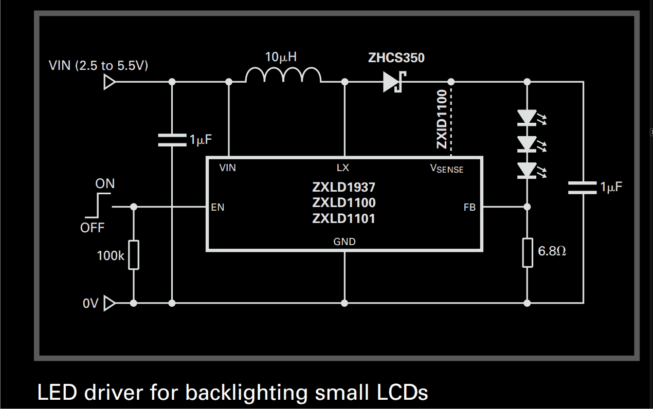
An effective LED driver circuit for LCD back lighting application has been discussed here which utilizes the IC ZXLD1100/1101/1937 from ZETEX.

The proposed circuit is based on the principle of PFM inductive boost converter concept.
The circuit is able to handle six series connected LEDs, powered by a Li-Ion cell and up to eight LEDs from a supply of 5 volts.

The ZETEX ICs are able to provide a good 350 mAof current for driving the above LEDs through a boost of up to 28 volts from the above discussed supply sources.

The minimum current required for keeping the IC operational is around 0.5uA, below which the IC shuts down itself.

The converter output is variable and can be varied by applying definite PWM control pulses across the enable pin out of the IC.

Depending upon the frequency of the fed PWM, the generated output is either chopped or a true continuous analogue.

You'll also like:

  • 1.  Blinking an LED with Arduino – Complete Tutorial
  • 2.  Make this 2 Pin Bi-Color LED Flasher Circuit
  • 3.  Sequential Timer Circuit using Transistors
  • 4.  Make this Red LED Sign Circuit
  • 5.  Ceiling LED Lamp Driver Circuit
  • 6.  Simple LED Circuits

About Swagatam

I am an electronic engineer (dipIETE ), hobbyist, inventor, schematic/PCB designer, manufacturer. I am also the founder of the website: https://www.homemade-circuits.com/, where I love sharing my innovative circuit ideas and tutorials.
If you have any circuit related query, you may interact through comments, I'll be most happy to help!

Reader Interactions

Have Questions? Please post your comments below for quick replies! Comments should be related to the above artcile Cancel reply

Your email address will not be published. Required fields are marked *

Primary Sidebar

Calculators

  • 3-Phase Power (15)
  • 324 IC Circuits (19)
  • 4017 IC Circuits (52)
  • 4060 IC Circuits (25)
  • 555 IC Circuits (98)
  • 741 IC Circuits (19)
  • Arduino Engineering Projects (83)
  • Audio and Amplifier Projects (114)
  • Battery Chargers (82)
  • Car and Motorcycle (94)
  • Datasheets (46)
  • Decorative Lighting (Diwali, Christmas) (33)
  • Electronic Components (100)
  • Electronic Devices and Circuit Theory (36)
  • Electronics Tutorial (116)
  • Fish Aquarium (5)
  • Free Energy (34)
  • Fun Projects (13)
  • GSM Projects (9)
  • Health Related (20)
  • Heater Controllers (29)
  • Home Electrical Circuits (102)
  • How to Articles (20)
  • Incubator Related (6)
  • Industrial Electronics (28)
  • Infrared (IR) (40)
  • Inverter Circuits (98)
  • Laser Projects (12)
  • LED and Light Effect (93)
  • LM317/LM338 (21)
  • LM3915 IC (25)
  • Meters and Testers (65)
  • Mini Projects (148)
  • Motor Controller (67)
  • MPPT (7)
  • Oscillator Circuits (26)
  • PIR (Passive Infrared) (8)
  • Power Electronics (34)
  • Power Supply Circuits (77)
  • Radio Circuits (10)
  • Remote Control (48)
  • Security and Alarm (61)
  • Sensors and Detectors (120)
  • SG3525 IC (5)
  • Simple Circuits (75)
  • SMPS (29)
  • Solar Controllers (60)
  • Timer and Delay Relay (53)
  • TL494 IC (5)
  • Transformerless Power Supply (8)
  • Transmitter Circuits (40)
  • Ultrasonic Projects (16)
  • Water Level Controller (45)

Calculators

  • AWG to Millimeter Converter
  • Battery Back up Time Calculator
  • Capacitance Reactance Calculator
  • IC 555 Astable Calculator
  • IC 555 Monostable Calculator
  • Inductance Calculator
  • LC Resonance Calculator
  • LM317, LM338, LM396 Calculator
  • Ohm’s Law Calculator
  • Phase Angle Phase Shift Calculator
  • Power Factor (PF) Calculator
  • Reactance Calculator
  • Small Signal Transistor(BJT) and Diode Quick Datasheet
  • Transistor Astable Calculator
  • Transistor base Resistor Calculator
  • Voltage Divider Calculator
  • Wire Current Calculator
  • Zener Diode Calculator

© 2023 · Swagatam Innovations