In this article I have explained a couple of inverter circuits featuring an automatic feedback control for ensuring that the output does not exceed the normal specified AC output level, and also does not exceed the specified overload conditions.
What is Feedback Control in Inverters
A feedback control in inverter is generally incorporated to control the output voltage and output current and prevent it from exceeding beyond dangerous limits.
In this system, the output AC mains voltage is first dropped to a proportionately lower level, and fed to the shut down pin of the control IC. The stepped down feedback voltage now follows the output AC and varies up/down accordingly, in a proportionate manner.
The control ICs shut down circuitry comares and monitors this feedback signal with a fixed ference derived from the battery volatge of the inverter.
In an event that the output voltage tends to rise above the predetermined value, and increase beyond the reference level, it activates the error amplifier, which shuts down the inverter output PWM. Once this happens, the output voltage instantly dips, causing the feedback signal to decrease below the reference value. This situation prompts the shut down feature of the IC to get disabled, and the IC starts working normally again.
If the output yet again tries to rise beyond the unsafe level, the above process is repeated in the identical manner, and this goes on continuously and rapidly, ensuring that the output voltage is never allowed to surpass the specified unsafe level.
Feedback Control in SG2524/SG3524 Inverters
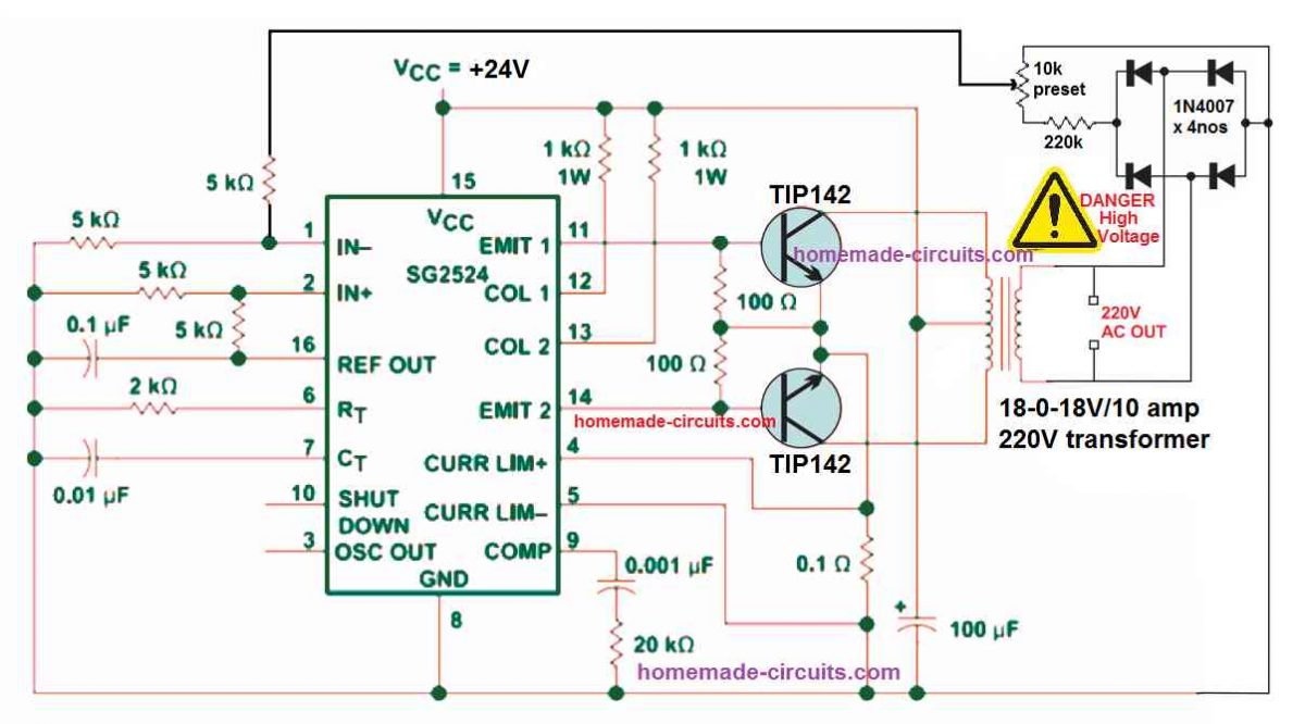
The first example circuit belw shows how an automatic feedback control can be added to a SG2524 inverter circuit. The same concept can be also applied to all the other inverter versions, using the IC SG3524, and SG3525.
You can refer to the following two datasheets for exactly knowing how the pinouts of the IC SG2524 IC are designed to function:
The feedback control loop is configured in the following can be understood with the following points:
The 220V AC output is first rectified using a 4 diode bridge rectifier circuit.
The rectified high voltage DC is dropped to a lower DC level, at around 5V to 10V through the voltage divider network built using the 220K resistors and the 10K preset.
The 10K preset is used to adjust the feedback voltage until the output voltage is controlled just at the right level.
The feedback is taken from the 10K preset's center arm and fed to the error amplifier's non-inverting input pin#1 of the IC 2524.
This error amplifier is nothing but an opamp set internal to the IC for controlling the PWM of the output pin#11 and Pin#14.
The inverting or the (+) input pin#2 of the op amp is clamped at a fixed reference level of +2.5V through the couple of voltage divider resistors configured around the pin#2 and pin#16 of the IC. The +5V reference potential is derived from pin#16 of the IC and then dropped to 2.5V using the two voltage divider resisters.
Since the pin#2 of the error amplifier is fixed at 2.5V reference, means that if the pin#1 of the opamp rises above the 2.5V level would instantly trigger the PWM feature of the IC, causing narrowing of the output PWM to the transistors.
The feedback 10k preset is adjusted in a such a way that feedback voltage at pin#1 reaches the 2.6 V mark as soon as the output voltage reaches the specified unsafe high voltage level.
In such situations, when the pin#1 receives a 2.6 V, it will cause the internal error amp to activate, narrowing the output PWMs to the transistors, which will in turn cause the output voltage to reduce to the safe lower levels, appropriately.
Simple Voltage Feedback Control for SG3525 Inverters
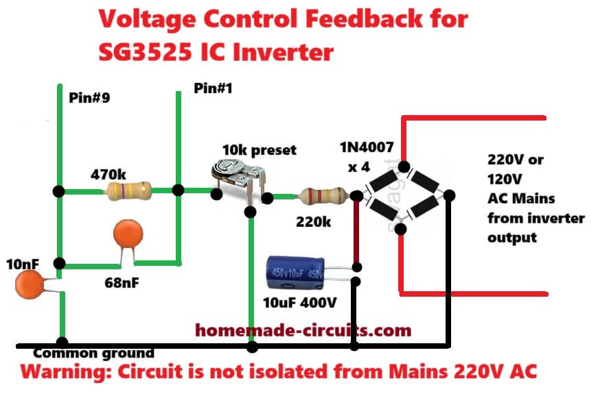
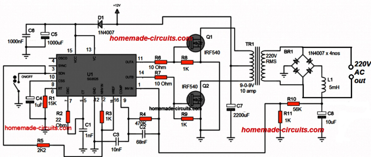
This is simple non isolated direct feedback circuit for SG3525 inverter. First high voltage 220 AC comes from inverter output. Then four 1N4007 diodes convert this AC into DC.
After that 220k resistor drops high voltage and 10uF four hundred volt capacitor smooths out DC ripple. Now 10k preset is used as voltage divider to set output voltage to220 or 120 volt. Sampled voltage directly goes to Pin number one of SG3525 IC.
Between Pin number 1 and Pin number 9 there is 470k resistor and 68nF capacitor network for error amplifier compensation to stop oscillation.
Also 10nF capacitor is connected from Pin number 9 to ground for extra filtering. When output AC voltage increases, voltage at Pin number 1 also goes up.
Since Pin 2 is supposed to be at fixed reference, high voltage at Pin 1 forces internal error amp to reduce duty cycle and output voltage comes back to normal level.
Main warning is that this whole circuit shares common ground with AC output, so it is not isolated and touching any part can give dangerous electric shock.
Adding Feedback in IC 555 Inverter
You might have already gone through the post which explains how to build simple 555 based inverters.
Although all these inverters are decently designed and will produce the intended 220 V or 120 V from an easy IC 555 set up, these do not have a built-in feedback system for ensuring a constant output voltage.
The following figure shows how an ordinary IC 555 inverter could be transformed into an enhanced inverter through an easy feedback loop control network.
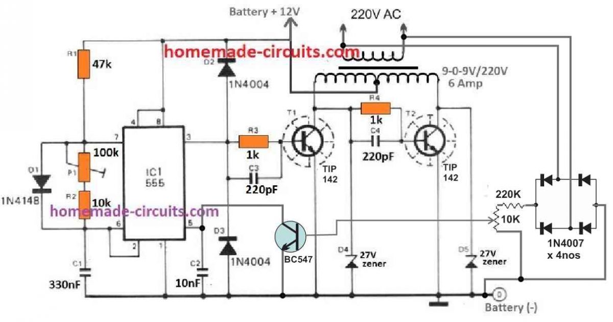
In this circuit also, we find that the 220V output from the transformer is first rectified to a DC level, and then it is stepped down through a resistive network comprising of a 220K resistor and a 10k preset.
The 10k preset center lead is configured with the NPN transistor BC547, whose collector can be seen connected with the pin#5 of the IC which is control input of the IC.
We know that normally when pin#5 is open, the PWM at the output pin#3 of the IC has a maximum PWM, however, as the potential at pin#5 is reduced, the output PWM also gets reduced proportionately.
Grounding the pin#5 causes the output PWM at pin#3 to become very narrow, with almost zero average voltage at this pinout.
In the IC 555 feedback circuit, when the output voltage tends to rise above the unsafe high voltage threshold, as per the setting of the 10k preset, the base of the BC547 slowly starts getting biased. When this happens, the BC547 begins conducting and causes the pin#5 of the IC to get gradually grounded. The grounding of the pin#5 of the IC causes the output PWM at pin#3 to get narrower, which in turns causes the output voltage to drop to the normal levels.


Questions & Answers
Good job sir,your unrelenting effort is of great help to us.
It is my pleasure Evans!
Hay it’s me again. After blowing 4 egs002 and who knows at least 40 MOSFETs, I am done with the egs002. You have provided all the circuits that are needed to make the inverter that I want to build. It’s going to be a pure sign wave operating at 170 volts DC to produce about 115 volts AC. I liked the formula 1.41 I was using.707 I know it’s about the same. Anyway. You are the only one I have found who takes the time to work with us guys and nobody can answer the questions about that egs002. I don’t want to ask too many questions right now let me get something built. But real quick when I use the voltage feedback everyone is saying to use a 200k resistor. That’s for a 220-volt output would i use a 100k since my output voltage is 115 volts I may go higher to 125 volt AC max with a 175 volt DC battery pack. I have a friend that has a business in lead acid batteries he give me them for free. You should see this battery pack that i made. So there is no need for me to go with a transformer. Thanks for your time.
Thanks Art, I am sorry to hear about your problems with EGS002
Actually I have never used this module practically so I won’t be able to suggest much on this. I wish I could.
The feedback line has a 220K resistor in my above circuit. I have connected the 220K resistor in series with the 10k preset.
I hope you build and succeed with tbis project soon
All the best to you!
Everything that I have built from you has worked, so don’t see why your schematics will fail me. So what you are saying is it doesn’t matter whether the feedback voltage is 120 volts or 220 volts right, I am going to build what your schematics tell me to use. I also found your article on how MOSFETs work I read it once I will read it 10 times more if I have to. A lot of engineers have blogs like yours you go into depth about the circuit and you answer all the questions people ask of you. its very help full. Thanks, I will get started will be in touch.
.
Thank you very much, and glad my circuits worked for you. Yes whether 120V, or 220V, you can use the 220K series resistor. I appreciate your kind thoughts
Hello sir Swagatam good afternoon. I have a circuit inverter from his website, the circuit is modified sine wave with lm555 timer and cd4017. The question is.. How can I add to that circuit this circuit with feedback control. Thanks you so much
Hello Carlos, is the diagram from the following article:
https://www.homemade-circuits.com/modified-sine-wave-inverter-circuit-2/
did you use the second diagram??
Hello, No sir, I used the number 1
Carlos, you can try the the following modification for the feedback control
Thanks Swag for this article, but how can I incorporate the overload shutdown to my sg3524 module.
Hi Seun, please see the pin4 and pin5 configuration with the 0.1 Ohm resistor. This resistor value decides the overload or over current shut down.
Please sir, how do calculate the resistor per load
You can use the following formula
R = 0.2 / Load current limit
Sir, God bless you for really coming up to each of my questions.please sir, I have some few questions which are:1 the above sg2524 inverter circuit,at the output, do you need to filter out the ripple signal? Because is not a smooth dc output, and if yes then what value? secondly,I want to cut off for my inverter at a power rating of 1000w,due to the formula in some of your feedback to bro.seun.sir,I calculated it and it was R=0.0024,am using 12v battery and load current of 83.3amp.so how many 0.1ohm resistor do I need a connect in parallel? thanks sir.
Thanks Eniola, to tackle the ripple you can add a 2200uF capacitor right across the battery terminals, and also a 100uf right across the IC supply pins.
For calculating the number of 0.1 ohm resistors you can use a parallel resistor formula….please use the formula or you can try any online resistor calculator software to get the approximate value of the resistors.
Please sir, how can I calculate the resistor in parallel? Or is it 1/R=1/r1+1/r2+1/r3…… orJust give me the formula sir. But if it is the above formula ostensibly,I will parallel about 10 of 0.1ohm resistor for 1000w cut off.but if not just introduce me the appropriate formula.thanks sir, looking forward to your quick reply
Eniola, you can use the mentioned formula for calculating the number of parallel resistors with some manipulation. You can put 0.1 for R1, R2, R3…and check how many resistors are required to get close 0.0024…then further use the result with the parallel formula to get the precise value.
You can online calculators also
Hello sir, pls the above sg2524 circuit above
1. What is the wave form output, if it’s square wave, how can we improve it to modified sine wave or pure sine wave
2. What is the wattage output, what components should we add to improve the wattage to 1000watts
3. Pls sir, where is the input side in the circuit, i.e the 12v plus and minus side.
4. Lastly sir, which battery volts does it use. 12v or 24 volts
Thanks very much sir for answering.
Hello Anthony, the output of any inverter will be always square wave unless an SPWM concept is employed.
The wattage will always depend on transformer, and battery ratings, and also the mosfet. You will have to upgrade it accordingly. I think I have explained you regarding this in one of the earlier comments.
The battery supply must be connected across the transformer center tap, and the common emitter points of the transistors.
It can be used with a 12V or a 24V battery.
Please how can I add low battery shutdown circuit to #10 to latch, the design I have personally cut off but comes up when the battery voltage rises
You can add the following op amp design with the first circuit for the low battery cut off:
Thanks Sir, please how can use this for 48v input
Hi Seun, you can drop the voltage to 12V for powering the IC through a 4k7 1 watt resistor, and a 12V zener diode.
Please sir, what adjustment can I do to work with 48v input.
Thanks sir, please is there any alternative to using pin 16, the board is already plastered. Swagatam, help out
Pin16 gives the 5V reference to the op amp, if you don’t want the reference from pin16, you can create it using an external 1K resistor, and a 5V zener diode.
Thanks Sir for your assistance, I have tried both ways, they cut off but didn’t latch, any help.
I guess it won’t latch, instead it will cause the output PWM to become minimal so that the battery usage becomes negligible for the load
Please Sir, how can I have low battery cut that will shut down and latch for Sg3524 circuit
Seun, you can use the following modification for latching the inverter during low battery voltage
Please sir the op amp low battery you posted in your comment section, 1. Sir please how can i adjust the cutt off voltage manually using the 10k preset without variable or bench power supply?
2. Is it the above circuit applicable to 12v system using Sg3524 ic.
Thanks for your response in advance.
Godspower, you will need to feed the circuit supply lines with the low voltage at which you want the cut off to happen. Initially rotate the preset wiper upto the positive supply rail. Then switch ON the low voltage supply, and adjust the preset until the output of the op amp just turns high and the LED illuminates.
yes it is applicable to 12V supply
Mr Swag i am very greatful sir for this quick response God in heaven will continue to bless you.
please sir do not be annoyed because of my questions as i am an electronics hobbyist and i have built my inverter am currently using , please one more question sir.
I built my 12volt battery using lithium ion battery but no Bms, but base on my research i discovered that the maximum full voltage is 12.6v, now i want the battery to be discharged up to 9v since am personally using the battery. question sir
1. Is it possible to adjust the above circuit to cut off at 9v?
2. Advice me on the minimum voltage to discharge from the battery?
Hello Godspower, you must adjust the preset for a 10V low battery cut off, meaning, if the supply reaches 10V, the opamp output will become high, and if the voltage increases above the 10V, for example if the voltage is 10.2V then the opamp output will become low.
Hi sir, I want to add a low battery cut off at 11v, imitating your low battery cut off circuit.sir, I want to cut off at 11v and I think for it to cut off at 11v the pin 3 has to be set at a constant voltage of 11v and the pin 2 will be set at,let me use 12v,as the battery voltage get utilized the voltage at pin 2 start to drop on till it gets to 11v which will trigger the opamp output high.since the ic is employ as a comparator.im I right? If right please,just give me resistor value to implement that.or just give me the formula for voltage drop by resistor with the current.
Eniola, that’s right, however instead of using fixed resistors you must use a preset at pin#2, so that the exact 11V cut off can be adjusted, as implemented in the SG3535 circuits:
https://www.homemade-circuits.com/sg3525-pure-sinewave-inverter-circuit/
Thank you sir for the circuit. sir please please what is the frequency of the above circuit for sg3524 and Ic 555
You are welcome Godspower, the frequencies should be around 50 Hz, but for the IC 555 you will have to tweak using the 100k preset.
Thank you sir for the quick response sir.
Please sir from the Sg3524 circuit above, i could not find the following resistors, 5k, 2k, 20k, please sir is it posible for me to replace 5k with 4k7? and connect (2) 1k in series and (2)10k in series to give me 2k and 20k repectively? Thank you sir God bless you sir.
You are welcome Godspower, yes definitely all those options are possible, no problems with that.
Thank you so much sir very grateful
Thanks a lot sir. I was so impressed that you are helping us here and also responding swiftly and well. Thanks so much sir.
You are welcome!
very nice article
Good day mr swag
pls do u have any article
of how to make an inverter without using an ic and of about 50HZ-60HZ speed to switch on/off
Hi Martin, you can try the following diagram:
https://www.homemade-circuits.com/how-to-make-simple-200-va-homemade/
1-CAN MOSFET IRF3205 BE USED INSTEAD OF TRANSISTOR
2-HOW CAN INCREASE THE WATTAGE OF THE OUTPUT
1) Yes it can be used.
2) Wattage can increased by implementing the steps explained in the following article:
https://www.homemade-circuits.com/upgrading-low-power-inverter-to-high/
GOOD DAY SIR
PLS DO U HV ANY ARTICLE OF AN INVERTER THAT CAN GIVE AN OUTPUT OF 7.5KVA AND HOW CAN INCREASE THE OUTPUT… THANKS IN ADVANCE, WAITING FOR UR REPLY
Hello Ebuka, you can refer to the following articles for learning the procedures:
https://www.homemade-circuits.com/upgrading-low-power-inverter-to-high/
https://www.homemade-circuits.com/how-to-calculate-and-match-inverter/
Hi sir
can i connect 470ohm + 100ohm resistor to use as 560ohm
Sure, you can do that!
HI SIR
THANKS FOR UR PREVIOUS REPLY
PLS AM A BIT CONFUSED ABOUT SOME ELECTRICAL PART PLS WHEN U WROTE 1K RESISTOR DID U MEAN 100ohm
(2)DID U HAVE AN ARTICLE DAT CAN POWER ELECTRIC IRON
Hi Martins, please specify the comment reply which you are referring to?
All inverter circuits can be used for powering an electric iron provided they are upgraded as per the iron wattage..
I MEAN IN THE PLACES U WROTE 1K RESISTOR DO U MEAN 100 ohm
In the first diagram everything is correct, the shown 1K are also correct.
HI MR SWAG, THANKS FOR UR PREVIOUS REPLYS I IT REALLY HELPED ME A LOT :
MY QUERY IS, IS IT POSSIBLE TO REDUCE THE VOLTAGE IN A CAPCITOR ,ie, IF I HAVE A CAPACITOR OF 50v 4700uf CAN I USE RESISTOR TO MAKE IT 25v 4700uf .
You are welcome Martins, the capacitor voltage value determines it maximum holding capacity. If you supply 25V then the capacitor will store 25V, so it depends on how much voltage you are feeding to it.
And please do not in write capital letters.
Pls @ sir swagatam, is the inverter diagram above using sg2425 a pure sine wave or modified sine wave output inverter. Thanks for your reply
Anthony, the circuit is square wave.
Also sir what is the output wattage of the inverter diagram above using same ic sg2524. Thank you.
wattage is 70 watts
Ok , thanks sir, but sir how can I make it a pure sine wave
You will have to create an SPWM circuit as I have explained below, and then integrate it with the transistor bases, or mosfet gates of the inverter
https://www.homemade-circuits.com/how-to-generate-sinewave-pwm/
Also pls sir, how can I increase the wattage output
You can read the following post for more info:
Calculate Battery, Transformer, MOSFET in Inverter
Hello sir swagatam,iam into the full bridge type of inverter cause i use a small transformer for double power output. Please, can you tell how to connect this feedback to any diagram of a full bridge inverter using sg3524 of your choice that had discussed in one of your articles ,i would really appreciate. Show with a diagram for my quick understanding please,thanks.
Hello Evans, for your full bridge inverter also you can apply the same feedback network which has been shown in the above article.
Pls why my inverter always give me no feedback, and i try to rectify it most of time but yet same things.
Sir what is the ways out.
Which circuit did you use?
your site is extremely valuable to the DIY community!
Thanks for sharing this information.
I have a question about using a CT 220-110 output transformer for a “split phase” backup power supply for North America.
My question is this. if I use a CT 220v output transformer ie 220v output with 110v between L1 and CT, is it possible to load balance this arrangement?
If I’m not clear in my explanation, I can try and clarify.
Thanks
Doug
Thank you very much and glad you found this site useful.
I think, yes it is possible to load balance the secondary side of the transformer to get two output phases and a single common neutral at the center
Sir, am an electrical/electronic engineering student. Can you please direct me or help me with circuit diagram for wind turbine inverter, at least that can power 60watts bulb, charge a laptop and a mobile phone. Or maybe 100watt inverter for my
vertical axis wind turbine project
Daniel, you can use any one of the circuits from the following article for your requirement. Just make sure the transformer is rated at 9-0-9V, 8 amp or 10 amp, and the windmill is able to supply around 12V with 7 t 8 amp current.
7 Simple Inverter Circuits you can Build at Home
Hi sir
I must thank you for giving beaginers like us a chance to interact based on what we don’t understand.
My question is, what is the voltage value I will get at pin 14 and pin 11 respectively if I use 24v as my vcc
Thnks
Thank you Aminu.
You will get an average voltage of about 11V, and a peak voltage of around 24V on the output pins of the IC SG3535, when 24V is used as the supply input.
Thank you sir
Hi sir
What is the work of latch in pulse with modulation?
Not sure about it! I have not yet studied this concept!
Hi Swagatam. a diagram of the 12-230V inverter 4047 with feedback circuit, please. Thank you.
Hi Alexandru, you can do it in this way:
Connect a bridge rectifier circuit at the output of the inverter.
Create a resistive divider across the positive/negative lines of the bridge rectifier, using a 220K resistor and a 100K preset.
Make sure to connect the 100K preset at the ground or the negative side of the bridge rectifier.
Take a BC547, connect its base with the wiper arm of the 100K preset.
Connect the emitter to the negative output of the bridge rectifier.
Connect the collector of the BC547 with the Ct pin of the IC 4047.
Make sure to connect the negative line of the bridge rectifier with the negative of the battery.
After this, adjust the 100K preset so that the inverter output voltage is unable to rise above a desired threshold such as above 220V etc
thank you Swagatam for the prompt reply.
You are welcome Alexandru!
Pin#1 is the Ct pin of the 4047 IC
thank you, sir
Please swagatam, I also a related issue with pic16f716 inverter module, it voltage feedback and as well as the current feedback. Can I get a diagram? Thanks sir
Hi AYODELE,
Since I do not know the shut-down pinout details of the PIC16F, it can be difficult for me to solve your query.
good day swag. thank for your reply and help so far, you are really doing a great work. my question is, the 5k resistors at the voltage divider stage of the opamp, can they be changed to 10k since I can’t get an exact value
Thank you Hillary! You can use 4k7 for all those resistors
good day swagatam. I am faced with construction of automatic voltage regulator (stabilizer) please do you have a circuit diagram for that
Hi Hillary, here’s a simple stabilizer circuit which you can try:
https://www.homemade-circuits.com/how-to-make-small-homemade-automatic/
Hello sir ,pls is it safe to connect the output of the bridge rectifier to your circuit directly without the use of a capacitor? As you did not use one in your diagram.
Then, if voltage at transformer tends to increase, does the output voltage of the diode rectified increases too?
Hello Igbinoba, Actually a small value capacitor should be connected with the feedback bridge rectifier. You can add a 10uF/400V capacitor with the bridge outputs. Yes the bridge output will increase when the inverter voltage increases and vice versa.
Sir for the above circuit 2v truck battery is used, will the same circuit with same components work for 12V 35Ah battery
Hi Alwin, yes the circuit can work with 12V also, just make sure to use a 9-0-9V transformer for a 12V operation.
is it possible to make a 50hz inverter using atmega8 ic ?? and if possible can you make one???
It is definitely possible, but my Atmega coding knowledge is not good, so I cannot make it.
I am looking for an inverter LED circuit (not an emergency light circuit), curious after seeing Philips Inverter LED bulb 9W or 12W, which glows on mains if power is there, else switches to Li-ion battery mode. Thanks.
I haven’t yet designed it….. I will try to design it if possible and let you know.
Please can I use UPS transformer
Yes you can…
Can I use 12volt battery 7amp on the first inverter.
Yes you can….
How many watts of resistor can I use
All are 1/4 watt 5% CFR
Sir 0.1uf and 0.01uf and 0.001uf and 0.1ohm is not in market what can I use replace it
These values are actually very standard values, you cannot replace them with other values….
Is those uf the same with 100nf
yes, 100 nF = 0.1 uF
0.001uf =100pf
0.01=10nf is it correct
Use the following calculator:
https://www.digikey.in/en/resources/conversion-calculators/conversion-calculator-capacitance
Can this inverter give me constant output watts
Yes, as long as the battery is not over loaded.
Can I use SG3524 to replace sg2524
Yes you can…
How many voltage of 100nf and 10nf and 1nf capacitor can I use
All should be 50 V or above….normally nF and pF capacitors are all 50V by default
Please who can help me with this with this inverter I tried many times and I failed who can guide me to make it work
The above circuit was taken from the datasheet of the IC 3524, so it cannot be wrong.
If you build the circuit without understanding, then you can never succeed. You will have to understand and build the circuit step-wise, only then you can troubleshoot the faults and ultimately succeed, otherwise you will keep struggling.
How can I add more mosfet to ag3524 or tip to this inverter sg3524 for more output watts
You can read the following article for more information regarding how to upgrade the power output of an inverter,:
https://www.homemade-circuits.com/upgrading-low-power-inverter-to-high/
Please help me know how to practically build a working igbt welding inverter especially the inverter section and the output section.I understand the theory but how to do it is the problem.Thank you.
IGBT welding circuit is a very complex design, it cannot be explained through comments. You can refer to the following post for a related article:
https://www.homemade-circuits.com/smps-welding-inverter-circuit/
Hi,
I’m a beginner in need of your assistance with a simple PCB design for a Fan powered and ATX Inverter silent
electromagnetic generator proto… I only am left with a picture of the generator in question and electronics professionals may quickly figure out the wiring map of such a picture of the generator. In short, I need help with the schematic layout and can get started in my home workshop asap.
Hi, I wish I could help you, however, sorry, it may be difficult for me to solve your generator wiring problem, because my expertise is restricted to circuit diagrams and schematics only.
Mr Swatagam, thanks for your kind explanations on the two circuits. Please, the inverter circuits with 555 timer ic and 3524ic. How can I replace those transistors with MOSFETs?
I would like to see the diagrams of the two.
Thanks.
You can send it to my mail.
Hi Elisius, I cannot find the circuit that you are referring to, please provide me the link, so that I can check it out.
This is the link. But I later found where you posted.
Thanks.
Please, I have another request. I need these inverter circuit to be configured to have feedback.
&opi=89978449&sa=U&ved=0ahUKEwjXpveU2-uBAxWYXUEAHepeD8MQ5hMIBQ&usg=AOvVaw2v7gUQy60lxU0N4f8bG6pa" rel="nofollow ugc">
You can replace the the BJTs with MOSFETs in the 555 circuit, just make sure to replace the 1K gate resistors with 100 ohms.
For the feedback you can use the same feedback network which is shown for the 555 circuit. The collector of the BC547 must go to the pin#1 of the 4047 IC.
Please what changes can be done to convert and ordinary square wave inverter to modified sine wave
You will have insert a 40% deadtime to convert the square wave into modified sinewave.
How do I achieve it with sg3525 inverter driver you posted in this forum. Please suggest a schematics to achieve that the pwm ic above.
You can add a deadtime capacitor in the circuit and experiment with its value until a perfect modified waveform is achieved.
Can this circuit withstand refrigerator
That will depend on the transformer, MOSFET and battery capacities.
Hi senior Swagatam, I’ve been following your post for years. My question is, can a square wave inverter power a submersive pump machine? I’ve made one of your circuit using SG3525 3kv. I recoil the transformer 48 0 48. I used 48v battery. Everything worked fine but the transformer is overheating. The output MOSFETs, I used 6 pairs (12pcs) of irf260n
Thank you so much Barry, for being a dedicated reader of this blog.
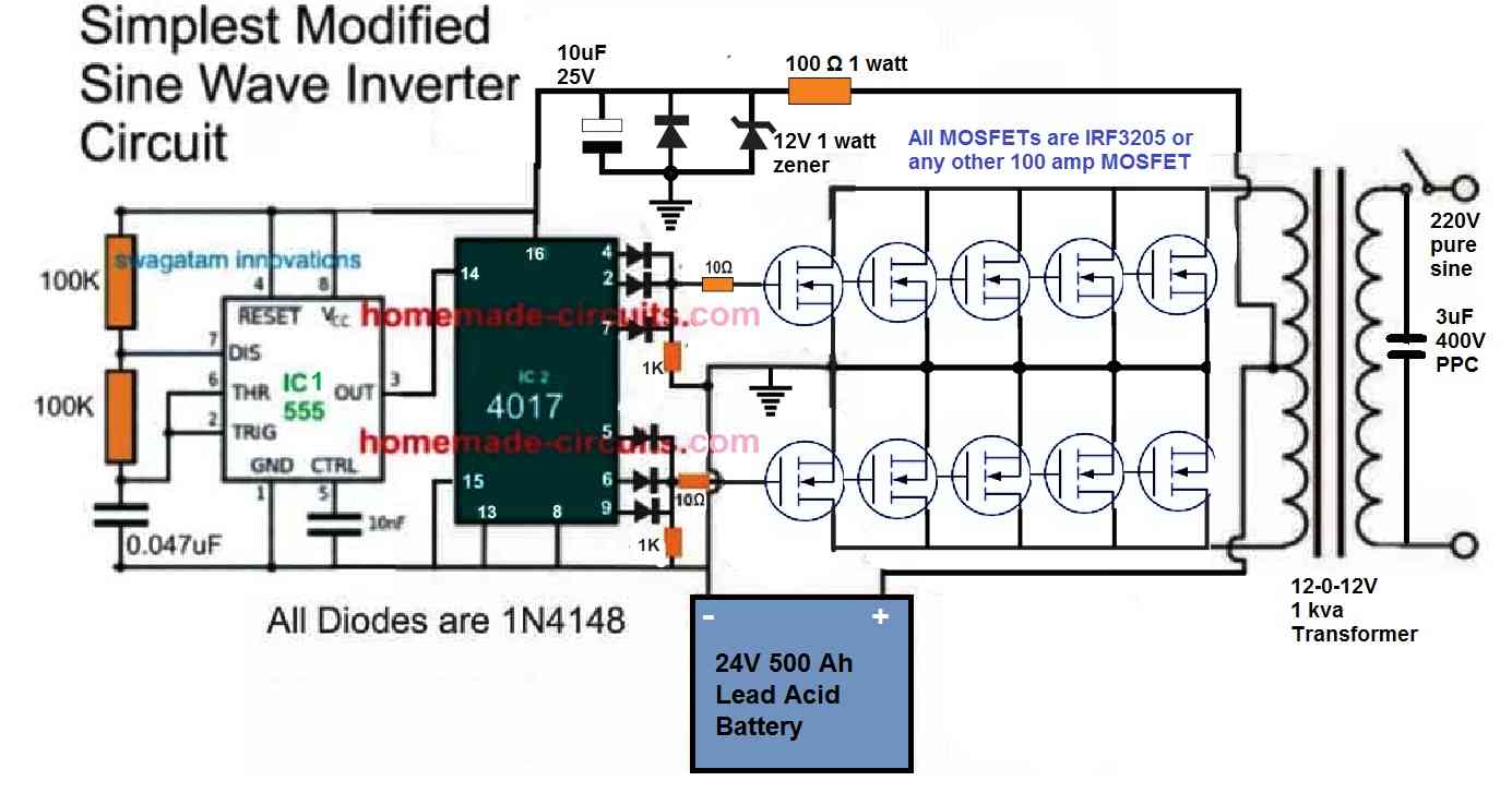
An appropriately rated square wave inverter can power a submersive pump motor, but the motor might make a lot of noise and heat up.
So you have to make sure your inverter is at least a modified sine wave inverter with a capacitor filter at the secondary side of the inverter transformer.
Here is an example design which you can effectively employ for the same;
You can change the transformer specifications accordingly to improve power efficiency.
good day boss, please can you share the circuit you used?
Hay me again looking for my last post found this topic on feedback circuit. Well first off the two boost converters work great paralleled I used , 2x. .
0.1 ohm 10-watt resisters one on each positive leg. When I got to about 2000 watts they got very hot. I guess that’s ok since that is why I used 10 watts. I also saw that a diode was used instead of the resister, could you explain the difference and in my case it would have to be a big diode of high current. I also saw your feedback circuit, going to put that to use. Thank you have the best web site, you cover everything, no need to go any place else.
ART
Thanks for updating the results. Glad the idea is working for you.
You last comment was posted under this article:
https://www.homemade-circuits.com/inverter-circuit-with-feedback-control/
Can you please tell me where is the diode placed in your boost converter circuit?
The function of the diodes could be to provide isolation across the outputs of the two boost converters.
You are most welcome, I am always happy to help!
What if instead of rectifying the output voltage for the feedback you just use a mobile charger that produce 5v for the feedback.pls will work?
No it will not work, because mobile phone will produce a fixed 5V and not a varying voltage.
Ok thanks
Can I use a 6v06v to 220v transformer from old ups instead
You can use it but then the battery will need to be around 7V or max 9V.
Thanks but what will be the minimum voltage the battery must get to indicate it is a low battery and can I replace the transistor with MOSFET.
A 12V battery may be considered low when its terminal voltage reaches 11V or 10.5V. Yes you can replace the BJTs with MOSFETs
I mean for 6v06v transformers I want to use u said I should used 9v battery max.but at what voltage will 9v battery be low
It will be around 8V…
Pls how can I add a feedback circuit to my cd4047 inverter that I build pls
you can try the following circuit:
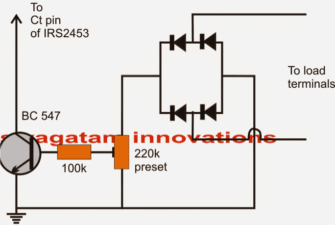
connect the collector of BC547 to the Ct pin of the 4047 IC.
Can I connect a 12v transformer to the inverter output before going to the bridge rectifier and the 220k, 10k preset for the feedback
If you use a small 12v step-down transformer for the feedback, then the 220k/10k divider will not be required.
Pls if I connect the feedback circuit to ic4047 as indicated can it still shutdown the inverter on a high load more than the inverter power as some inverter do. Pls I want to know
No, the previous circuit is only for regulating high output voltage, it is not an over load protector…
Hi. I have made this circuit but when i change the preset, the frequency of the ic changes instead of the duty cycle
Hi, In the 555 circuit the frequency might also slightly change when the 100k preset is adjusted.
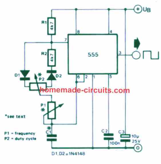
If you want to change only the PWM, you can replace the 555 stage with the following stage:
i mean sg3524 not 555
If you adjust the feedback 10k preset the frequency cannot change because that preset has no connection with frequency.
When feedback is adjusted the PWM is narrowed or widened, frequency remains the same.
Please measure the frequency across the CT capacitor.
Hay its me again, is it possible to add an sg2524 to an ZVS circuit. I have had somewhat of a working ZVS circuit. I am trying to make it more stable. When it works it works well, but some time later it blows up. The best mosfets that have worked for me is the hy3408 only problem is they can handle voltage to 80. The irf260n which the circuit calls for very tempemental and costly. Thanks for your time.
ART
Thanks Art, I think it is possible, however the crucial part is calculating the buck converter section. I am not well versed with ZVS technology, let me investigate more and then I can try to add more explanation…
Pic 18f2431 is it better than 16f72 and dsppic30f2010 in its ability to drive the fet/igbt effectively.
good day sir. i made the sg3524 circuit, i can vary the output but when i add a load of 10watt the voltage drops to about150v
Good Morning Hillary, You must verify the output voltage without the feedback connected. Check if it drops or not. If it does then either the transformer or the battery or the PWM setting may be malfunctioning.
the transformer i used was a 6v 0 6v to 220v that I got from an old ups I also need to tell you something about the oscillator,when I try to measure the reference voltage with respect to ground I was reading around 0.49 volts which I know something is wrong so I’m trying to see if I can send you the schematic of the oscillator if maybe you can advise me to build another one and I will just get some components.
You can send the schematic or you can refer to the following post, and check if you have built your inverter as per the given configurations or not.
https://www.homemade-circuits.com/sg3525-pure-sinewave-inverter-circuit/
I don’t know if u have seen the schematic, although with it help I was able fix it and implement feedback.the output does not drop anyhow any longer.but when I connect a fully charged battery 12.99v to the inverter,it draws too much current and the transformer makes a loud noise, although under 12v its behave normally,also I noticed the inverter still work at 8v and I know the battery is already low.pls those this happen because I used a 6v 0 6v to 240v transformer?
A feedback will not boost the output voltage if your voltage is dropping due to overload.
If it is working, then your inverter problem is not due to an overload.
I think you must follow a standard design as shown below for implementing a good standard SG3525 inverter circuit.
the ic am using is sg3524n
will this work pls???
It is correct and will work….
ok sir, thanks you sir.
I also want to ask what should be the maximum feedback voltage I mean when you rectify your AC I got sending it through your voltage divider what should be the maximum voltage is it that my maximum feedback voltage should be around 5 volts before it gets to the feedback I tried voltage divider
good afternoon I made an inverter using an sg3524n,although the oscillator is different from yours,which I still don’t understand the way the oscillator is yet,cause i got it from a spoilt inverter where the transformer of the inverter got burnt but when I actually use it to make my own inverter the issue was that there was no feedback and when Ioad is connected to the output it will varies depending on the load so I tried to implement feedback by using a 220v to 6v battery charger that utilize a transformer which the output is rectified to get 6v then I used a 10k fixed resistor and a 20K pot and I connected in such a way that when I measure the voltage at the mid terminal of the pot with respect to ground I get around 2.99v so I connected the positive of the feedback to ground of the battery the mid terminal of the pot to pin 1 of the sg3524n, but what happened is that when I turn on the inverter it does not output any voltage so I try removing the the positive of the feedback that was connected to the ground of the battery its comes on but when I connect the positive of the feedback voltage to the ground of the battery the inverter turns off,pls what could be the cause of this? is it that the feedback voltage is too much or I’m not doing something right?
Hi, If you have used pin#1 for implementing the shut down, then the inverter output PWM will shut down when the pin#1 voltage exceeds the pin#2 reference voltage.
So can you please what reference you have set at pin#2 of the IC?
So basically, you must adjust the feedback preset such that at the desired high output voltage (above 250V), the preset output has a potential that just exceeds the pin#2 potential, and then this feedback voltage can be connected with the pin#1 for inducing the quick shut down when the inverter output goes above the unsafe high output AC voltage.
thank you for the quick reply,sir.My goal is to prevent the inverter’s output from dropping under load by implementing feedback. I realized the shutdown issue was due to the output reaching 289V. I’ll set the inverter to shut down only if the voltage exceeds 240V.pls Will enabling this feedback shutdown feature also prevent voltage drops under load? Or do I need a different approach? I’ll check the reference voltage and update you tomorrow.”
That is not possible through any means, except upgrading the inverter power.
If your inverter voltage is dropping due to overload, that means your inverter and battery are not rated to handle the specific amount of load, which means this issue cannot be solved through a feedback facility.
To solve it, you may have to consider upgrading your inverter and battery power.
Good morning,the feedback is not boosting the output voltage,it just makes the output stable under load,but what happened is the when my input is 12.99v or 13v the inverter misbehave and the ouput get to 324v and it drwas too much current ams asking that does this happen because I use a 6v 0 6v to 240v transformer?
Ok, earlier you were discussing feedback for overload voltage drop, so I was referring to that issue. Yes, the high voltage is due to a 6V trafo and a 12 V battery, you can try a 9-0-9V transformer instead and check the response…
Good evening sir I actually implemented the feedback and it’s worked but lasted for like maybe 30 minutes this is the things sir the circuit I actually use was still my old oscillator circuit what I just did was use another external transformer and I try to use a voltage divider to implement the feedback but this is the thing when I tested it at first and it worked there was no voltage drop but when I realize that my battery was low ,I went to charge it but on retesting it again the inverter started to misbehave(output got to above 300v ,so I’ve been trying to figure out the issue that I was wrong with it,but my thought is maybe my voltage divider somehow is not right or my total feedback voltage(6v DC) was too low,I just want to ask that what could be the cause of this? I implemented the feedback it worked I captured the testing on camera and then on coupling the inverter and retesting after I recharge my battery,the inverter started misbehaving.
Hello Jerry,
Please provide me with the following details, I will try to figure out the issue.
1) Battery Ah value
2) Transformer voltages and wattage or current specifications.
3) Load wattage which is causing the voltage drop.
4) Battery voltage value at the time when the inverter output voltage is dropping.
For adjusting the feedback, you can simply do it by connecting an AC voltmeter to the output of the inverter transformer and then adjust the feedback preset until the output voltage settles down to the correct required output voltage level…
good morning,I have successfully implemented the feedback now and it is working,the issue before was the if I add capacitor for filtering either the output or feedback voltage the inverter misbehave so I remove all capacitor except from the oscillator circuit and it worked I added snubber circuit to the output though.now I have another question I noticed my MOSFETs warms up quickly when my feedback is now working,is it because I did not use a transistor at pin 11 and pin 14 like to function as a MOSFETs driver?,cause I have I seen two YouTuber did it but never explained why.
Hi, I am glad you could solve the problem so fast.
A driver transistor may be required for a MOSFET if the load is a high current load, otherwise not.
So for small inverters below 200 watt, driver transistor may not be required.
Just make sure to use gate resistors of small value, and put reverse diodes across these resistors.
good morning,pls do you have the schematic for the this so I can follow it?
Hi, you can try the arrangement as done in the following concept:
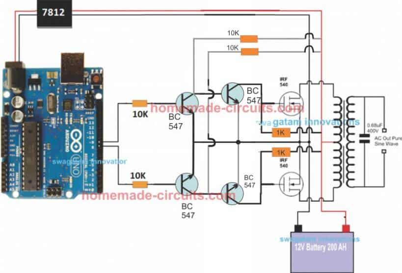
https://drive.google.com/file/d/1g1A6ua4Bw9Fxl_I96uJ_gGRwwCDPNap6/view?usp=drivesdk
what about this?
It is not opening…please get the link in the “shared” mode..
it is working now sir.
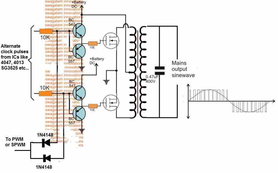
Yes, now I can see the diagram, but your concept is not very efficient, because discharging the MOSFET gate through the 1k can be slow and dangerous for the MOSFETs. Instead you can use a totem pole design, as given in the 2nd diagram below.
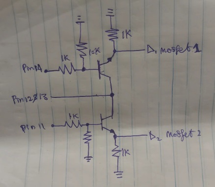
https://drive.google.com/file/d/1y_k110TcAp0FD7MXUTDEkyjjEcE14hvS/view?usp=drivesdk
which is more efficient among the two sir you gaver sir?,pls sir is there any component am missing out?
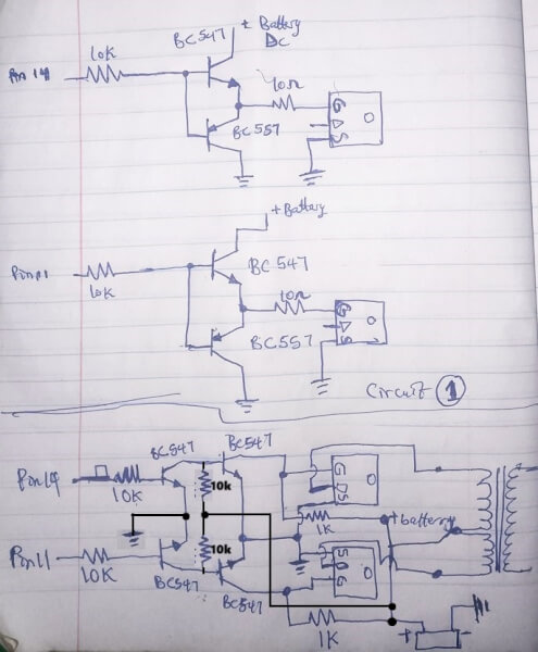
Both the designs are good, but the bottom one is better since it connects the MOSFETs gates directly to ground during the off switching periods. Your second design had a few mistakes, i have corrected them now:
You can access it now,sir
It is telling me to request access, please check your email ID.
my MOSFETs already has a 10k resistor from it source joined to another 10ohm resistor that goes to it gate and the junction where the two resistor joins together is where the Signal is sent to,so is the resistor connection not discharge?
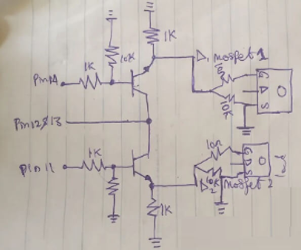
The gate current from 10 ohm has to pass through the high resistances of 10k and the 1k to reach ground for discharging, which is not good. The 10ohm end must have direct access to ground during the off periods of the oscillator output.
Please use one of the two configurations which I showed you previously.
but,sir I already bought component for circuit 1
No problem Jerry, You can use circuit 1 also, it will also work fine.
https://drive.google.com/file/d/1JLNH2vQWX9U98APID09i_wgj8zC9WCYZ/view?usp=drivesdk
pls sir is it ok to add a 10k resistor to the mosfet like this?
The resistor between the emitter and ground of the totem pole BJTs is not required, instead you can connect the 10k directly between the gate and source of the MOSFETs.
I have 4 MOSFETs in Parallel with each other and another 4 parallel MOSFETs for driving my transformer,the thing if I am to add the resistor from gate to source I will need to do that for all of my MOSFETs,and I already the mosfet,to add the resistor will the somehow stressful,the thing is the 10k resistor is already connected to MOSFET like this for each side of transformer and only one 10k was used for each side.
For connecting MOSFETs in parallel, just join their 3 relevant pins together, in parallel…
sir, when I implemented circuit 1 into my oscillator,it worked, but then my feedback was affected,my inverter started Misbehaving the output was no longer stable again.was could be the cause?also my inverter is sensitive to capacitor at it output or even at feedback so what could be the cause?
Jerry, please do not associate any capacitor with the feedback network, however connecting a capacitor at the output of the inverter should not affect the inverter performance. Make sure the capacitor is a non-polar PPC or MKT type such a 2.2uF/400V PPC etc. Moreover you need this capacitor mostly when you are using a modified PWM or SPWM sinewave inverters topologies, otherwise it is not required.
when I return my circuit to old no (totem pole driver) ,I was able to retune my feedback again and capacitor no longer disturb it ouput,so pls what went wrong that if I add the totem pole is disturb my feedback?,cause I remove a 10k resistor from pin11 to gnd and another 10k from pin 14 to gnd.
Using totem pole for the MOSFETs should have no effect on the performance of the inverter, in fact it might only improve…
Since you have used the feedback with pin#10 of the IC so again no problems with that.
You can try connecting a 10k directly between the gate and source of the MOSFETs and check the response…
what I was trying to say is that before I implemented the totem pole driver I already added feedback and it is working,when I power capacitive load with it it handles them also,but I noticed my mosfet got warm to quickly that is why I added the totem pole driver and on doing that the my inverter output stated misbehaving it was not stable going from 100v to 200v to and fro,but yesterday I added those 2 10k I mentioned to gnd and then I was able to finetune my feedback,but I added capacitive load and all of a sudden the voltage started fluctuating again,pls what is happening? thanks for your effort on me.
Then I think you should remove the totem pole and try the other driver configuration which I had suggested you using two NPN transistors. Make sure to connect each and every resistor correctly, otherwise it will not work:

good evening, sir. happy new year. it been a while like a year since I work on my diy inverter, since am in school, but few day ago, while reading a course called power electronics, where I was drawing the waveform of bridge rectifier, I realized I never understood them cause I used ur circuit to design my feedback circuit for my diy inveter although the oscillator circuit is different, the issues was I always thought that the anode if a diode is the positive terminal and cathode for gnd, this was the idea I had while designing the feedback for my diy inverter, I mentioned earlier that when I implemented it at first it work even with capacitive load, after neating and coupling the inverter it misbehaved, this use due to me connecting my positive of my feedback voltage to gnd and negative or gnd through the voltage divider to pin 1, I never released this till after a year, I tried my best to find the issues, till I don’t even remember what I did that made the while system work with the feedback, but still misbehaves with capacitive load, although after my exam if I go home I would open everything and inspect what I did, cause hmmm, until after a year that I realized how bridge rectifier works, and the anode of the diode will be your ground, I pray I don’t just chastise myself when I see all my connection in the inverter. about the driver I will fix them using 4 npn transistor(the second method you show me), am also thinking of rebuild the whole osillator surcuit using your circuit entirely, that will be for maybe a second inverter and lastly thanks for all the help and advice it really helped, alot!!. the website update is nice also👌👌.
pardon me if you see this message more than once, I don’t even know if it is sent or not, that is the reason for the multiple resend
I would like to add that a thought came to me, that I can utilize your transistor driver which drine the primary winding directly, but instead used it to drive the gate of a mosfet instead, is this also ok?
Thank you Jerry for your kind and honest feedback…I appreciate it very much.
If you want to use a BJT driver for the MOSFET gates then make they are two of them connected in inverting mode, or in a totem pole mode.
Morning, sir. i am happy to announce that my inverter is up and running and these are the modification i made.
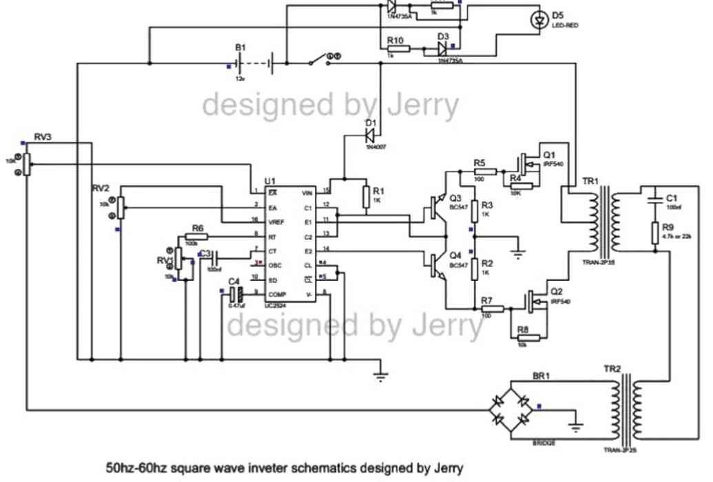
Thank you Jerry, it looks great, thank you for updating your tested design here…much appreciated.
https://drive.google.com/file/d/1sDAfqSz0v9xgZB20mmUiM3PCMeF3gXIt/view?usp=drivesdk
what will happen if you remove the 10k resistor from the oscillator pin ,with it affect the performance,cause when I want to add the totem pole driver I remove mine and my inverter was misbehave was it responsible for that?
Whether or not you connect a 10k between the oscillator output and ground does not make any difference, and will not have not any kind of effect on the inverter performance.
can 30uf/450v Ac capacitor and AC circuit breaker be used to stabilize inverter output voltage?
Please show me the circuit diagram, I will try to figure it out….
https://drive.google.com/file/d/1HJ1BjVdX1m5d9tyioweUeXkwcNFR9wXL/view?usp=drivesdk
this is what i finally did,the feedback is working,but there is catch under capacitive load the output increases e.g phone charger, capacitor etc.,but if I put a 40w resistive load (incandescent bulb) and then plug any capacitive load it remains stable and don’t increase, pls what is the cause?,apart from this it is working fine my MosFets are not getting warm too quickly.i also want to add battery low circuit and fuse pls any idea?sport for so many resend I don’t know if you will see this one.
Capacitive loads like phone chargers or plain capacitors mostly pull reactive power, not real power. Because of this, the inverter thinks there is not much load so voltage can rise or go unstable, mostly if the feedback is not properly designed. Now when you connect a resistive load like a bulb, it pulls real power continuously so inverter starts regulating voltage properly. After that even if you add capacitive loads, still the voltage stays stable because real load keeps things balanced.
So you can try adding a 1k resistor at the output and check the results…
that is the issue if am going to use a resistor for the real load then I should be prepared for how to reduce the heat it is going to generate,pls what should I do about that?,also if am to use 1k pls what Watt should I use?and can even get it here cause it is not available.
Instead of a resistive method, please try connecting a 10uF capacitor across the output of the bridge rectifier and check the results.
By the way your MOSFET driver section looks bad…you must use the methods which I had suggested earlier.
Swatan.. I don’t know where to ask,,, I would like a circuit to make an inverted welder of at least 120 Amp to 250 Amp, I have type E ferrite cores from televisions, also the circular or round ones from vehicle audio amplifiers,,, but I need a diagram if possible checked
Hi, a TV ferrite core or an audio amplifier ferrite core will not be able to produce 200 amp current.
Unfortunately, I do not seem to have sufficient information about the details of this transformer at the moment..
swatan,,,, pregunto si tendrías algún circuito que pueda hacer para un soldador tipo invertir, para hacer si me das un esquema y detalles lo haré soy experto en electrónica..
Felix, I have answered to your question previously, but no problem I will answer it again.
Designing Inverter type welding circuit is possible, but 250 amps is huge, I have no idea which ferrite core would be required for such high current application.
Good sir. I have a problem with my sg3524 circuit.
I built this inverter with feedback voltage correction circuitry but when power it, its actually working is giving out 220v as i set it but while working the mosfet is extremely hot. I try everything i could but could not rectify the problem but when ever i remove the feedback topology and return it back to the normal switching circuitry, it doesn’t hot at all but am not ok with the output as soon i inserted a load to it. It will drop from 220 to 140v.
I actually use 7.2v center tap transformer.
Hello Abdul,
Please add a snubber network across the MOSFETs as discussed in the following article, and also add a reverse diode across the gate resistors of the MOSFETs, and add a 10k resistor between gate and source of the MOSFETs, and check the results:
https://www.homemade-circuits.com/explained-snubber-circuit-for-mosfet-h-bridge/
https://www.homemade-circuits.com/rc-snubber-calculator-for-mosfets-relay-contacts-and-triacs/
https://www.homemade-circuits.com/mosfet-protection-basics-explained-is/
is it possible to achieve overload and shortcircuit protection using current transformer and op-amp in an inverter? If yes please help with a circuit diagram
Sure….Please refer to the following article:
https://www.homemade-circuits.com/load-current-control-through-current-sensing-transformer/
Hi sir, why is the feedback unstable? https://drive.google.com/file/d/1P1nT4NOcAflLR0wgv5w38ztkRjtSKv-W/view?usp=drivesdk
Johan, please make your circuit in this way, and then check:
I’ve checked but the voltage goes up and down https://drive.google.com/file/d/1PNzcsLdni5UE8shq1UUlGXNEHCU1RZ7i/view?usp=drivesdk
The feedback circuit which I gave is correct, I think the problem could be in your inverter circuit, please build the following circuit and check again:

Hi sir. It turns out that the correct one is that pin 9 of the SG3525 IC is fitted with a 4.7k rc resistor and a 2.2μF non-polar capacitor and pin 1 is connected to pin 9 which uses a 470k resistor and a 68nf capacitor.it has to be released and I have tested it and it no longer vibrates and the output is very stable
Thanks Johan, for updating the info, I am glad it is now working good for you good..
I made it using an isolated one using a small additional transformer for feedback using a voltage of 16v and the main transformer using a 600va ct 7v transformer using a 12v battery that has been tested to be capable of carrying the heavy load.
Thanks for the feedback and the useful information…
Good afternoon, sir. how is everything? well I am enjoying my inverter but I still want to make a better one, sir. pls sir is there anyway I can modify my inverter circuit to become modified square wave inverter, so that the range of load I can power can increase? maybe with ne555 or
..?
Hi Jerry,
To convert your existing SG3525 into a modified sine/sqaure wave inverter, you can increase the deadtime by upto 30%, then add a 1uF/400V capacitor at the secondary 220V AC side of the transformer.
Make sure your transformer voltage rating is 30% lower than the battery voltage, meaning if the battery voltage is 12V, then the transformer could be around 8-0-8V or 9-0-9V
Good morning, sir. I don’t know if my first message was sent. that is why I am sending this again. the ic I used is sg3524n ic. my transformer is 6.2v 0 6.2v to 220v. for the dead time how do I do it, sir? this is my inverter schematic.
Good Morning Jerry,
A resistor connected across this pin#7 and pin#5 will give you the dead time. Try a 100 ohm and check the response…
Sorry, my previous reply was for IC SG3525, not for SG3524.
I think it is better to use an external IC 555 PWM circuit for chopping the MOSFET gates for converting it into a modified or even a pure sine wave inverter…