If you are looking for an option to replace conventional welding transformer, the welding inverter is the best choice. Welding inverter is handy and runs on DC current. The current control is maintained through potentiometer.
By: Dhrubajyoti Biswas
Using Two Switch Topology
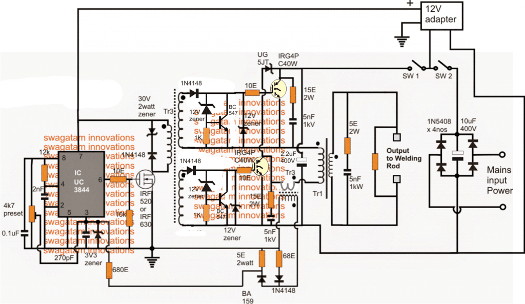
When developing a welding inverter, I applied forward inverter with two switches topology. Here the input line voltage traverses through the EMI filter further smoothing with big capacity.
However, as the switch-on current pulse tends to be high there needs the presence of softstart circuit. As the switching is ON and the primary filter capacitors charges via resistors, the power is further zeroed by turning the switching ON the relay.
The moment the power is switched, the IGBT transistors gets used and are further applied through TR2 forward gate drive transformer followed by shaping the circuit with the help of IC 7812 regulators.
Using IC UC3844 for PWM Control
The control circuit used in this scenario is UC3844, which is very much similar to UC3842 with pulse-width limit to 50% and working frequency to 42 kHz.
The control circuit draws the power from an auxiliary supply of 17V. Due to high currents, the current feedback uses Tr3 transformer.
The voltage of 4R7/2W sensing register is more or less equal to the current output. The output current can be further controlled by P1 potentiometer. Its function is to measure the feedback’s threshold point and the threshold voltage of pin 3 of UC3844 stands at 1V.
One important aspect of power semiconductor is that it needs cooling and most of the heat generated is pushed out in output diodes.
The upper diode which consists of 2x DSEI60-06A should have the capacity to handle the current at an average of 50A and loss till 80W.
The lower diode i.e. STTH200L06TV1 also should the average current of 100A and loss till 120W. On the other hand, the total max loss of the secondary rectifier is 140W. The L1 output choke is further connected with the negative rail.
This is a good scenario since the heat sink is barred from hi-frequency voltage. Another option is to use FES16JT or MUR1560 diodes.
However, it is important to consider that the max current flow of the lower diode is twice the current to that of the upper diode.
Calculating IGBT Loss
As a matter of fact, calculating IGBT’s loss is a complex procedure since besides conductive losses switching loss is another factor too.
Also each transistor loses around 50W. The rectifier bridge also loses power till 30W and it is placed on the same heat sink as IGBT along with UG5JT reset diode.
There is also the option to replace UG5JT with FES16JT or MUR1560. The loss of power of the reset diodes is also dependent upon the way Tr1 is constructed, albeit the loss is lesser compared to the loss of power from IGBT. The rectifier bridge also accounts to power loss of around 30W.
Furthermore when preparing the system it is important to remember to scale the maximum loading factor of the welding inverter. Based upon the measurement, you can then be ready to select the correct size of the winding gauge, heat sink etc.
Another good option is to add a fan as this will keep a check on the heat.
Circuit Diagram
Transformer Winding Details
The Tr1 switching transformer is wounded two ferrite EE core and they both have the central column section of 16x20mm.
Therefore, the total cross section calculates to 16x40mm. Care should be taken to leave no air gap in the in the core area.
A good option would be to use 20 turns primary winding by wounding it with 14 wires of 0.5mm diameter.
The secondary winding on the other hand has six copper strip of 36x0.55mm. The forward drive transformer Tr2, which is designed on low stray inductance, follows trifillar winding procedure with three twisted insulated wire of 0.3 mm diameter and the windings of 14 turns.
The core section is made of H22 with the middle column diameter of 16mm and leaving no gaps.
The current transformer Tr3 is made of EMI suppression chokes. While the primary has only 1 turn, the secondary is wounded with 75 turns of 0.4 mm wire.
One important issue is to keep the polarity of the windings. While L1 has ferrite EE core, the middle column has the cross section of 16x20mm having 11 turns of copper strip of 36x0.5mm.
Furthermore, the total air gap and the magnetic circuit are set to 10mm and its inductance is 12uH cca.
The voltage feedback does not really hamper the welding, but it surely affects the consumption and the loss of heat when in idle mode. The use of voltage feedback is quite important because of high voltage of around 1000V.
Moreover, the PWM controller is operating at max duty cycle, which increases the power consumption rate and also the heating components.
The 310V DC could be extracted from the grid mains 220V after rectification via a bridge network and filtration through a couple of 10uF/400V electrolytic capacitors.
The 12V supply could be obtained from a ready-made 12V adapter unit or built at home with the help of the info provided here:
Aluminum Welding Circuit
This request was submitted to me by one of the dedicated readers of this blog Mr. Jose. Here are the details of the requirement:
My welding machine Fronius-TP1400 is fully functional and I have no interest in changing its configuration. This machine that has an age is the first generation of inverter machines.
It is a basic device for welding with coated electrode (MMA welding) or tungsten arc gas (TIG welding). A switch allows the choice.
This device only provides DC current, this is very appropriate for a large number of metals to be welded.
There are a few metals such as aluminum that due to its rapid corrosion in contact with the environment, it is necessary to use pulsating AC current (square wave 100 to 300 Hz) this facilitates the elimination of corrosion in cycles with inverted polarity and turn the melting in the direct polarity cycles.
There is a belief that aluminum does not oxidize, but it is incorrect, what happens is that at the zero moment that it receives contact with air, a thin layer of oxidization is produced, and which from then on preserves it from next subsequent oxidization. This thin layer complicates the work of welding that's why AC current is used.
My desire is make a device that be connected it betwen the terminals of my DC welding machine and the Torch to obtain that AC current in the Torch.
This is where I have difficulties, at the moment of building that CC to AC converter device. I am fond of electronics but not expert.
So I understand the theory perfectly, I look at the HIP4080 IC or similar datasheet seeing that it is possible to apply it to my project.
But my great difficulty is that I do not do the necessary calculation of the values of the components. Maybe there is some scheme that can be applied or be adapted, I not find it on internet and I do not know where to look, that's why I ask for your help.
The Design
In order ensure that the welding process is able to eliminate the oxidized surface of an aluminum and enforce an effective welding joint, the existing welding rod and the aluminum plate could be integrated with a full bridge driver stage, as shown below:
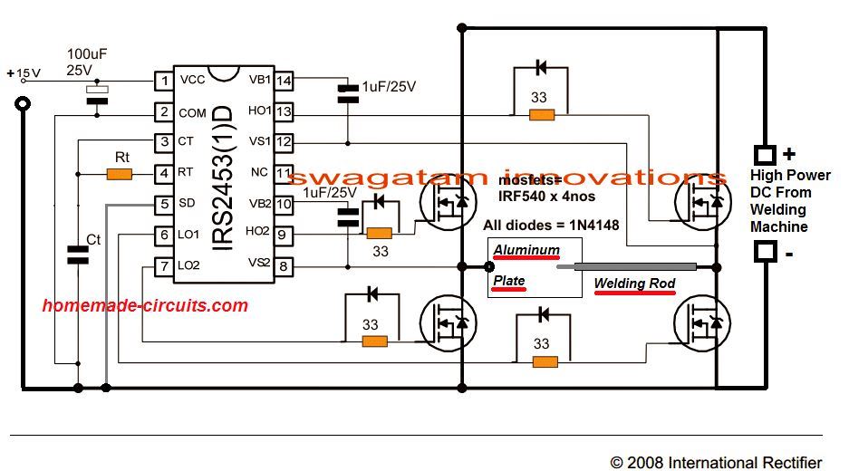
The Rt, Ct could be calculated with some trial and error to get the mosfets oscillating at any frequency between 100 and 500Hz. For the exact formula you could refer to this article.
Th 15V input could be supplied from any 12V or 15V AC to DC adapter unit.


Questions & Answers
would I be correct in assuming that this circuit (welding circuit) could be applied to a higher current mosfet module such as the vishay VS-FC420SA15?
And if I wanted to make a frequency display, it could be taken from any of the drive outputs of the IRS2453, but would be half the frequency of the inverter circuit?
I’ve downloaded the data sheet for the IRS2453, but it does not show these details..
Thanks for the reply, so the next question would be;
Has anyone successfully implemented this design as a square-wave DC welder add-on , or is it all theoretical “looks good on paper”?
Yes, if the MOSFETs are rated appropriately, then it can be used with the above design.
For the frequency measurement I think you can try it across the Ct capacitor of the IC…
sir why did my inverter produce high current and refuse to be controlled
gracias por toda esa información.
Dear Sir,
Can you send the schematic diagram for Intimax inverter welder machine model no BEST 310.
Thank your valuable support.
is that working sir ?
it is working, but recommended only for the experts in the field…
is it possible to make 60volt 20 amps SMPS with this design? thnx.
it is possible…
sempre estudo os seus circuitos. sao inovadores e faceis de entender. obrigado por compartilhar conhecimento
Thank you so much Wilson, glad you found my circuits helpful!
Sir will a field stop igbt with 600v and 40 amp rating work as I am not able to find the stated igbt in the circuit diagram
Shantanu, I think it should work, however it is recommended to use the one that is stated in the diagram.
Very good share
Hi
how are you I hope you are doing fine.
sir I have a question, and my question is ; what are the problems that caused the out put failure for the igbt inverter welding machine, and as a layman what’s the solution to the problems ?
Thank you sir!
Hi Sani,
IGBT can fail due to overload, over current and avalanche voltage issues. The solution is to implement appropriate protections for the IGBT such as overload and avalanche protections.
Good morning sir. but my igbt always got spoil during testing even without connecting transformer on it, what could be the problem it will first of all shows that it is working after fixing it during testing, but when I want to test again so that I can now fix the transformer one of the MOSFET will get issue or even the both of them, please help me I don’t know how to handle the situation. though the MOSFET is not the exact one on the diagram.
Good Morning Samson,
It is difficult to judge the fault because there can be many reasons, it could be the static discharge which could be damaging the devices or maybe the devices are duplicate quality and are therefore getting damaged without any load. It is very difficult for me to understand the fault without practically checking it.
excellent work my friend,i normally watch ur videos.kenya
Thank you Joseah!
12 volts or 24 volts ferrite core invertor schematic circuit for
3000watts required.
Ferrite transformer specification, the core and number of turns,
Which control IC suitable.
Could you please help me out.
Gopal
Sorry, Presently I do not have the circuit details for a 3000 watt ferrite inverter circuit.
Sir
In continuation with ferrite core invertor.My input 24 volts and out put 220 volts.
Ferrite core invertor.
Core and wire.
Can i use litz wire or any other wire.
Please suggest me.
Gopal
Yes you can use litz wire.
I want to use ferrite core invertor
For 3000 watts.
Which ferrite core dimension and wires sizes and turns your kindself
Can suggest us.
Regards
Gopal
The ferrite core dimensions will need to be calculated using complex formulas.
https://www.homemade-circuits.com/how-to-design-and-calculate-ferrite-core-transformers-for-inverters/
Thanks swagatham.
I have queries.
I want to contact.
Hi swagatam
Pleat what could be the cause of heating up of mosfet
Hi Samson,
The MOSFET can become hot if the SMPS transformer is not built correctly and does not correspond with the frequency of the IC.
how are you sir and thank you for your endless contribution for us in this site. what equivalent component can i use for IRG4P C40W please
Thank you Habtamu,
You can use any other 600 V 40 amp IGBT variant instead. You will have to find out by referring to datasheets.
Hi Swagatam
how much current this welding machine can deliver and what is te open ckt output voltage?
Hi Tamal, actually the article was contributed by an external author so I am not very sure about the exact output voltage and wattage of the unit
Hi Swagatam
its a really useful ckt. I have a question. Can I go for a say 500Hz ckt instead of a 50KHz ckt and use a smaller welding transformer. Normal transformer instead of a ferrite transformer?
Thank you Tamal,
If you not using a ferrite transformer then the size cannot be small, it can be huge using an iron core transformer for example.
That’s ok. But it will be probably 10 times smaller than 50 Hz transformer. Which is cheaper? a 50KHz system or a 500Hz system? Any calculation?
I just forgot to tell, that iron core probably cannot handle 500 Hz
Hello Sir, hope you are doing good.
I need your help ,I want to build a A welding machine unit made with a variable control for amps 0 to 200 amps, and volts variable 0 to 5 volts. It must have a voltage display and a current display, basically an adjustable welding machine but with adjustable voltage 0 to 5 volts.
Thank you.
Hello Ernest, for such high current you will require a big transformer, and a mosfet regulator. Can you access this big transformer, the regulator part can be designed by me.
Hello Sir, Thanks for your Kind response,
I can manage to get the transformers( all ferrite ?)
Also can you also add the voltmeter and ammeter connection( segment digital display will be better)
You can go ahead designing the regulator
Many thanks.
Hi Ernest, after some think I realized making a 5V regulator using a MOSFET can be difficult because mosfet gate do not work properly at voltages below 7V
Hello Sir, Noted with thanks.
You can design one within the desired voltage ranges and even a minimum12vdc will do .
Do not hesitate to modify my specs so as to get a working Inverter.
Thank you.
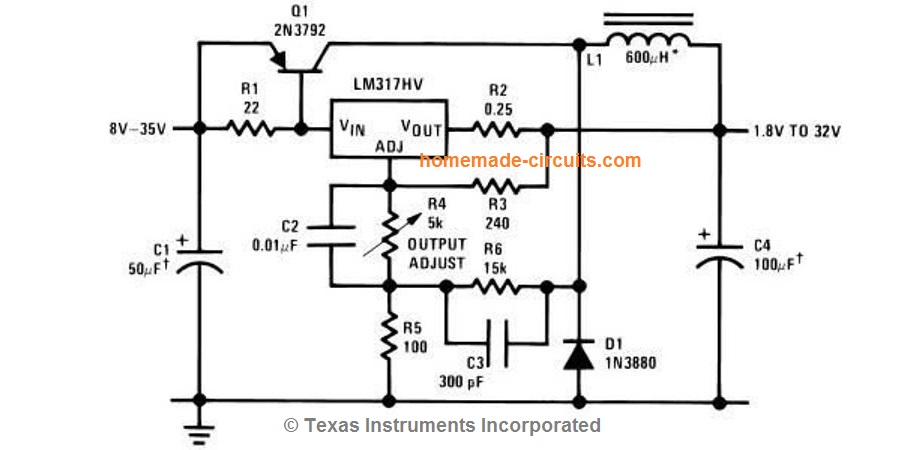
Hi Ernest, you can try the following circuit:
The mosfets can be IRFP2907.
The resistors R2 to R5 are current sensing resistors which may be calculated using the formula:
R = 0.6 / Max Current
Thank you Sir, for time and effort in responding to my inquiries.
One more Q? Confirm I can do the welding with just the regulator Circuit you shared?
No problem Ernest, yes according me the regulator will be able to handle the indicated voltage range at 200 amp variable current. Make sure to put the MOSFETs on a large heatsink
Thank you Sir, this sounds great.
I am very grateful, may your hands and your generosity continue to be blessed abundantly.
I found your site very educative and encouraging moreover you are there for any assistance that may be needed. All Credits goes to you Mr Swagatam .
Thank you and good bye for now.
Thank you Ernest, I am always glad to help!